Table of Contents
Advertisement
Quick Links
HEAT PRESS TECHNOLOGY
Operators Handbook
All products within the ADKINS range are labelled with CE marking and are manufactured and tested to comply with EC safety regulations.
All products within the ADKINS range are labelled with CE marking and are manufactured and tested to comply with EC safety regulations.
Rev B - 29/01/19
Rev B - 29/01/19
©2019 A. Adkins & Sons Ltd. All rights reserved. E&OE. V1.0.
©2018 A. Adkins & Sons Ltd. All rights reserved. E&OE. V1.0.
BETA MAJOR
Advertisement
Chapters
Table of Contents

Related Manuals for Adkins BETA MAJOR


Summary of Contents for Adkins BETA MAJOR
- Page 1 Rev B - 29/01/19 All products within the ADKINS range are labelled with CE marking and are manufactured and tested to comply with EC safety regulations. All products within the ADKINS range are labelled with CE marking and are manufactured and tested to comply with EC safety regulations.
- Page 2 Preface Dear User Welcome to the growing group of Beta Major Users. The product you have purchased has been carefully designed and manufactured to ensure that you, the user, will gain the maximum benefit. All Adkins products are specifically designed to ensure ease of use with particular attention to safety requirements.
-
Page 3: Table Of Contents
Installation Transport instructions Installing the machine Electrical requirements Pneumatic requirements Adjusting the pressure How to operate the Beta Major Starting with the Beta Major Working with heat transfer materials Material fusing Pressing pad assembly Shutting down the machine Fault diagnosis... -
Page 4: Introduction Beta Major
It is ideal for high volume production with low operator fatigue. The work area of the Beta Major is 38 x 50 cm (15 x 20 in), but machines may have to special order, optional smaller sized interchangeable worktables of any size and various shapes within this table size. -
Page 5: What Did You Receive
What did you receive? The Beta Major has been placed in a cardboard box, and held in place with foam and banded onto a pallet, or as requested. The following articles should have been delivered: Beta Major complete with mains cable and plug ... -
Page 6: Specifications Of The Beta Major
It is ideal for high volume production with low operator fatigue. The work area of the Beta Major is 38 x 50 cm (15 x 20 in) but machines may have, to special order, optional smaller sized interchangeable worktables of any size and various shapes within this table size. -
Page 7: Safety
Safety The Beta Major has been equipped with various safety features to ensure operator safety. A thermal cut-out on the heating element shuts off the power C ± 15 to the element if the temperature exceeds 235 C (455 ± 27... - Page 8 These may include air extraction and/or masks for personnel. Please refer to Page 14 for an illustration of the Beta Major machine. Page 5...
-
Page 9: Installation
Electrical requirements The Beta Major should be connected to the mains supply (nominally 230V AC) by the mains cable provided and a suitable plug. A qualified person should carry out this work. -
Page 10: Pneumatic Requirements
Pneumatic requirements The Beta Major and Minor should be connected through a filter regulator to a compressed air supply capable of delivering 60 cu. litres/min at a pressure of 3.5-7 bar max. (2 cu. ft./min at 50-101.5 psi.). -
Page 11: How To Operate The Beta Major
Starting with the Beta Major 3.1.1 Turn on the Beta Major; the on/off switch is on the left side of the front of the swing head. Set the machine controls as necessary. See instructions for adjusting the pressure, 2.5, and the operation of the time temperature unit, Page 15. -
Page 12: Material Fusing
Material Fusing 3.3.1 When the press is to be used for the fusing of fusible interlining/heat bonding etc., ascertain from the supplier of the material to be used, the correct settings for time and temperature for the process. Approximate settings are usually within the following:- C - 170 C (250 Heat Setting... -
Page 13: Fault Diagnosis
Shutting Down (cont.) To shut down in an emergency, press the red button on top of the machine head. If the emergency stop button is actuated, it will need to be unlocked by turning it anticlockwise before the machine will run again. - Page 14 Hints and Tips (Cont.) Article having transfers applied is locked in contact between pressing pad and heat plate. Pressing pad is in good condition, is flat and making complete contact over the whole area of the heat plate. See Pressing Pad details.
-
Page 15: Maintenance Of The Machine
Maintenance of the Machine Daily Maintenance For good press results it is important to keep the press surfaces clean. Wipe the surface of the heat plate with a dry non-abrasive cloth before use when the plate is cold. When the heat plate is hot and is not in use, keep in the open position away from the silicone pad. -
Page 16: Machine Drawings, Diagrams And
Machine Drawings Diagrams On the following pages are the schematic diagrams for the Beta Major machine. General Layout…………………………….. Page 14 Control Unit – Operation…………………. Page 15 Exploded Diagram and Parts List………… Page 16 Electrical Diagram…………………………. Page 17 Controller Electrical Diagram……………. -
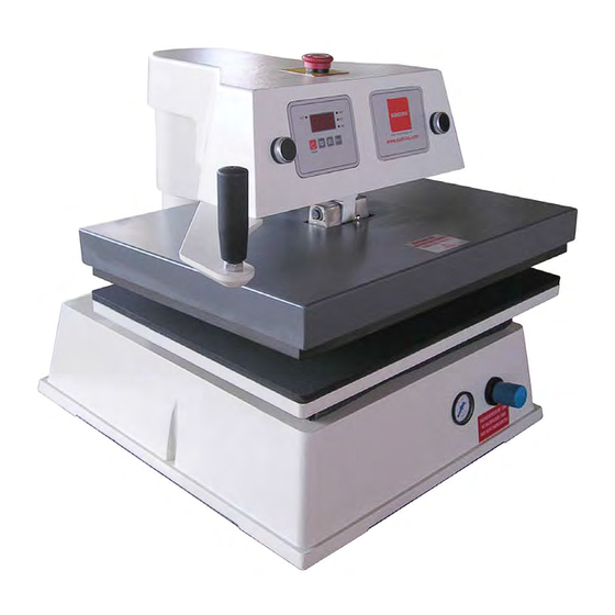
Page 17: General Layout
5.1 General Layout of the Major and Minor Machine EMERGENCY STOP TWO PUSH BUTTON CONTROL TO OPERATE MACHINE TIME/TEMP CONTROL UNIT HEAD SWING AWAY HANDLE PRESSURE ADJUSTMENT PRESSURE GAUGE Page 14... -
Page 18: Control Unit Operation
5.2 Operation Of Control Unit, Setting Time and Temperature (The table must always be in the down position before the controller is set) Setting Temperature Switch Press; Display 'TEMP' indicator will light up. TEMP TEMP Press 'MODE' button to select 'Set' on indicator. -
Page 19: Exploded Diagram And Parts List
4b Back controller power board BMC322/B 4c Controller back plate AM628/C 4d Green button controller BM322/YF Green rocker switch BM448 Overlay R/H Adkins Major fascia BM629 Pivot post top cap AMC106 Micro switch cam AMC373 Pivot "o" ring AMC204 10 Swing arm handle... -
Page 20: Machine Electrical Schematic
5.4 Electrical Diagram Page 17... -
Page 21: Controller Wiring Diagram
5.5 Controller Electrical Diagram Page 18... -
Page 22: Pneumatic Schematic
5.6 Pneumatic Schematic Page 19... -
Page 23: Design Change
6. Design Change With the policy of constant improvement and/or modification to meet changing conditions, the right is reserved to change the design and/or specifications at any time without prior notification, and therefore specifications may vary and not be in accordance with this manual. Page 20... -
Page 24: Guarantee
“as is”. A. Adkins & Sons Limited does not warrant that the functions of the press will meet the customer’s requirements or expectations. -
Page 25: Declaration Of Conformity
A. ADKINS & SONS LIMITED DECLARATION OF CONFORMITY Application of Council Directives: Machinery, Low Voltage. E.M.C. Standards to which Conformity is BS EN ISO 12100:2010 - Safety of machinery: Basic Technology, Principles of Design. Declared: BS EN 60204-1:2006+A1:2009 - Safety of machinery: Electrical Equipment of Machines.
Need help?
Do you have a question about the BETA MAJOR and is the answer not in the manual?
Questions and answers