Table of Contents
Advertisement
Quick Links
HEAT PRESS TECHNOLOGY
Operators Handbook
All products within the ADKINS range are labelled with CE marking and are manufactured and tested to comply with EC safety regulations.
All products within the ADKINS range are labelled with CE marking and are manufactured and tested to comply with EC safety regulations.
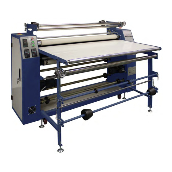
ALPHA CALENDER ROLL-MASTER 1.2
Rev C - 07/02/19
Rev C - 07/02/19
©2019 A. Adkins & Sons Ltd. All rights reserved. E&OE. V1.0.
©2018 A. Adkins & Sons Ltd. All rights reserved. E&OE. V1.0.
Advertisement
Table of Contents

Related Manuals for Adkins Alpha Calender Roll-Master 1.2


Summary of Contents for Adkins Alpha Calender Roll-Master 1.2
- Page 1 Rev C - 07/02/19 All products within the ADKINS range are labelled with CE marking and are manufactured and tested to comply with EC safety regulations. All products within the ADKINS range are labelled with CE marking and are manufactured and tested to comply with EC safety regulations.
- Page 2 No part of this publication may be reproduced by any means without the prior written permissions of A. Adkins & Sons Limited. Alpha Calender Roll-Master 1.2 is a trademark of A. Adkins & Sons Limited. Please read this manual carefully and keep it with your machine at all times for reference.
- Page 3 All Adkins products are specifically designed to ensure ease of use, with particular attention to safety requirements. Should you discover any fault or damage upon receipt of this product, you should immediately contact your supplier.
-
Page 4: Table Of Contents
Contents Introduction Machine Benefits Specifications Safety Instructions Safety Tips Warning Signs Installation Unpacking Installation of Worktable Installation Notice Operation Guide Operation Notice Maintenance Cleaning Lubrication Blanket Care Heating Oil Replacement Machine Drawings and Diagrams General layout Roller configurations Control Panel operations LH Cabinet layout RH Cabinet layout Electrical diagram... -
Page 5: Introduction
1. Introduction The Alpha Calender Roll-Master 1.2 has been developed after continuous feedback from end users and aims to provide market leading specifications with ease of operation and economical running costs. It is capable of thermal transfer from roll-to-roll, roll-to-pieces and pieces-to-pieces and for any type of cotton, polyester or polyester mix. -
Page 6: Machine Benefits
Machine Benefits Below is a brief list of the many benefits of the Alpha Calender Roll- Master 1.2: Most of the machine rollers are precisely cut using computer operated CNC cutting machines to provide a completely parallel shaft. This allows for very long material transfers without any tracking. -
Page 7: Specifications
Specifications Below are the specifications for the Alpha Calender Roll- Master 1.2 Heating Media Voltage Single Phase 230 Volts AC Power (Heater - 4.5 kW) (Motor - 0.5 kW) No. of Heating Elements No. of Feed Rollers No. of Collection Rollers Machine Size 152.5(L) x 40(W) x 124(H) cm 60(L) x 15.7(W) x 48.8(H) in... -
Page 8: Safety Instructions
Safety Instructions Before operating the Alpha Calender Roll-Master 1.2, please read the safety instruction carefully to fully understand the machine’s primary structure, function, and operation method. Training in machine operation and maintenance procedures is also required, for all personnel involved in the day-to-day use of the Alpha Calender Roll- Master 1.2. -
Page 9: Warning Signs
Safety Tips (cont.) 1.4.1 Heat and Power Switches Both the Heat and Power switches are located on the Control Panel. To immediately stop the machine from heating, turn off the Power Button. This will stop the power for heating, but will still allow power to pass to the motor. 1.4.2 Blanket Maintenance When the heat transferring is completed, turn off the heater (as above) but allow the motor to rotate the blanket until the... -
Page 10: Installation
2. Installation The Alpha Calender Roll-Master 1.2 should be sited in a secure, flat and dry location with good ventilation and enough space for safe and efficient operation. A safe and adequate electrical supply should be provided with sufficient protection for the rating of the machine and with easy access to a trip/safety switch. -
Page 11: Installation Notice
Installation of Work Table (cont.) Step 4 Installation of Work Table (20) Place the metal table onto the installed holder and fasten with four screws. Step 5 Installation of the Tension Shaft (17), including the installation of the Gear Reducer (3). Install similarly to the Tension Shaft at the top of the machine but please note that you will need to install the metal plates on the left and right cabinets first. -
Page 12: Operation Guide
3. Operation Guide Before switching on the machine, make sure that all of the electrical wires are connected correctly. The body of the machine must be connected to ground. Press the main power switch and transform start switch. Then, adjust the rotary speed on the Speed Adjustor (2) to optimum values. - Page 13 Operation Notice (Cont.) direction of revolution using the Blanket Reverse Switch (18) until the blanket moves back to the central of the oil drum. During use the blanket may track to either side, this is a nor- mal operation and should not be a cause for concern. As men- tioned above there is a tracking adjusting roller (45) on the machine.
-
Page 14: Maintenance
4. Maintenance Cleaning Care should be taken to keep the machine clean and tidy and to keep the electric circuit box and transducer free from dirt and dust that may accumulate over time. Do not open the Transformers protective shield to avoid electric shock. -
Page 15: Machine Drawings And Diagrams
5. Machine Drawings and Diagrams General Layout.…………………………………….. Roller Configurations……………………………… Control Panel Operation...…………………………. LH Cabinet Layout.………………………………… RH Cabinet Layout.………………………………... Electrical Diagram.………………………………… Page 11 ... -
Page 16: General Layout
5.1 General Layout No. Part Name Fabric Rewind Shaft Shaft Pin and Chain 17 Fabric Tension Shaft Barrier Paper Shaft 18 Drum Direction Switch Gear Reducer 19 Guide Shaft Cabinet Door 20 Work Table Name Plate 21 Barrier Paper Rewind Shaft Cooling Fan 22 Drum Speed Controller Castor Wheel... -
Page 17: Roller Configurations
5.2 Roller Configurations No. Part Name Barrier Paper Charge Roller Tensioning Bar Work Table Fabric Charge Roller Transfer Paper Charge Roller Transfer Paper Exhaust Roller Fabric Exhaust Roller Barrier Paper Exhaust Roller Page 13... -
Page 18: Control Panel Operations
5.3 Control Panel Operations This is located at the front of the left hand cabinet and controls the temperature of the drum. TEMPERATURE CONTROLLER °C °C OUT1 OUT2 CHB402 Operation Procedure 1. Power up the machine at the mains supply switch. 2. - Page 19 Control Panel Operations (Cont.) The Fabric charge speed controller is located at the front of the left hand cabinet and controls the speed of the fabric charge roller. Fabric Charge Speed Controller DRUM SPEED ROLLER SPEED MODE ENTER MODE ENTER MODE ENTER STOP...
- Page 20 Control Panel Operations (Cont.) POWER START TEMPERATURE START DRUM START Power Start, Temperature Start and Drum Start Buttons Xxxxxxxx x xxxxxx xx xxxxx xxxxx xxxx xxx xxxxxxx xxxx. Xxxxxxxx x xxxxxx xx xxxxx xxxxx xxxx xxx xxxxxxx xxxx. Operation Procedure 1.
-
Page 21: Lh Cabinet Layout
5.4 LH Cabinet Layout No. Part Name Solid State Relay Cooling Fan Cicuit Breaker Timer Relay Heater Relay Terminal Board Page 17... -
Page 22: Rh Cabinet Layout
5.5 RH Cabinet Layout No. Part Name Slip Ring Bearing Block Main Motor? Gear Reducer Chain Toothed Wheel for Drive Belt Shaft Bearing Block for Oil Drum Tracking Adjusting Roller Chain Tensioner Page 18... -
Page 23: Electrical Diagram
5.6 Electrical Diagram Page 19... -
Page 24: Troubleshooting
6. Troubleshooting Symptom Cause Solution The temperature is Solid State Relay is Replace Solid State too high or rises damaged Relay slowly There is damage in Replace the faulty one or more sets of Electric Tube(s) set(s) Electric Tubes in the Heater Unit Aging of one or Replace the faulty... -
Page 25: Design Change
7. Design Change With the policy of constant improvement and/or modification to meet changing conditions, the right is reserved to change the design and/or specifications at any time without prior notification, and therefore specifications may vary and not be in accordance with this manual. ... -
Page 26: Guarantee (Limited Warranty)
“as is”. A. Adkins & Sons Limited does not war- rant that the functions of the press will meet the customer’s require- ments or expectations. -
Page 27: Declaration Of Conformity
A. ADKINS & SONS LIMITED DECLARATION OF CONFORMITY Application of Council Directives: Machinery, Low Voltage. E.M.C. Standards to which Conformity is BS EN ISO 12100:2010 - Safety of machinery: Basic Technology, Principles of Design. Declared: BS EN 60204-1:2006+A1:2009 - Safety of machinery: Electrical Equipment of Machines.
Need help?
Do you have a question about the Alpha Calender Roll-Master 1.2 and is the answer not in the manual?
Questions and answers