Advertisement
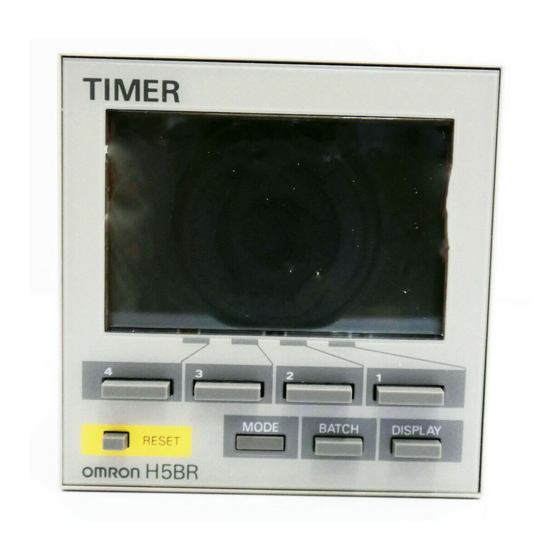
Multifunction Digital Timer
72 x72 mm Timer with Easy-to-use
Functions
Nine output modes accommodate a wide variety of
applications.
All parameters set by scroll-through menus
accessed from the front panel.
Field-selectable time ranges from 0.001 second to
9999 hours.
High visibility LCD display with built-in backlight.
Batch counting Function records the number of
completed cycles.
Contact and solid-state outputs available simulta-
neously.
Precision control possible to 0.001 second.
Four levels of key protection provided.
Selectable elapsed time (UP) and remaining time
(DOWN) display.
Conforms to EMC standards.
Six-language instruction manual provided.
Ordering Information
Functions
Contact type
Terminal form
Part number
Supply voltage
Note: Specify both the model and control power supply when ordering.
Model Legend
H5BR -
Type classifier
Accessories (Order Separately)
Soft cover
Shock prevention cover*
Note: Models with a shock prevention cover can be ordered by
adding "-500" to the end of the model number.
e.g., H5BR-B-500 (100 to 240 VAC, 50/60 Hz)
The cover provides finger protection conforming to
VDE0106/P100.
9 field selectable
One SPDT relay and two NPN open collector transfor output
18 terminal screws on rear of case
H5BR-B
AC
24/100 to 240 V, 50/60 Hz
DC
12 to 24 V
B: Standard
Y92A-72F1
Y92A-72T
Soft cover
Shock Prevention Cover
(conforming to VDE0106/P100)
Y92A-72F1
H5BR
RC
Y92A-72T
1
Advertisement
Table of Contents

Related Manuals for Omron H5BR Series


Summary of Contents for Omron H5BR Series
- Page 1 Multifunction Digital Timer H5BR 72 x72 mm Timer with Easy-to-use Functions Nine output modes accommodate a wide variety of applications. All parameters set by scroll-through menus accessed from the front panel. Field-selectable time ranges from 0.001 second to 9999 hours. High visibility LCD display with built-in backlight.
-
Page 2: Specifications
H5BR H5BR Specifications Model H5BR-B (Standard type) Classification Digital timer Mounting Flush mounting External connections Screw terminals Enclosure ratings IP54 (panel surface) Emission Enclosure: EN55011 Group 1 class A Emission AC Mains: EN55011 Group 1 class A Immunity ESD: IEC801-2: 4 kV contact discharge (level 2) 8 kV air discharge (level 3) Immunity RF-interference:... - Page 3 H5BR H5BR Ratings Rated supply voltage 100 to 240 VAC, 50/60 Hz 24 VAC/12 to 24 VDC (permissible ripple: 20% max.) Operating voltage range 85% to 110% of rated voltage Power consumption Approx. 8 VA at 50 Hz, 240 VAC; approx. 5 W at 24 VDC Reset and control signals Min.
-
Page 4: Factory Settings
H5BR H5BR Nomenclature Display Operation key 1. Power indicator 13. Increment keys (1 to 4) (Used to change the 2. Signal input indicator corresponding digit of the set 3. Reset indicator value. Used to change data in the 4. Gate indicator setting mode.) 5. -
Page 5: Operation
H5BR H5BR Operation Block Diagram LCD drive System clock LCD reference clock generator generator voltage generator LCDs Setting circuit LCD driver Key switch circuits One-chip Control microcom- circuits puter Input circuits (Re- set, control signal, Output circuits batch count reset, (OUT, batch output) key protect, gate) Power outage... -
Page 6: Operational Overview
H5BR H5BR Operational Overview Run mode Setting mode Present value, Press the set value MODE key Timing range Press the Press the DISPLAY key BATCH key Press the MODE key Batch count value, UP/DOWN mode set value Press the Press the MODE key DISPLAY key Output mode... - Page 7 H5BR H5BR Setting Item Table Mode Setting item Discription Setting procedure Run mode Set value Compared to the present value. Sequence when changing a digit using the incre- Determines the timing of the ment control output according to the keys (1 to 4). output mode.
-
Page 8: Run Mode
H5BR H5BR Examples Run Mode Changing the Set Value To change the set value from 3 hr 5 min to 4 hr 5 min, press the 3 key so that the number 4 appears in the hour’s place. & Pressing keys 1 through 4 increments the corresponding column by 1. -
Page 9: Setting Mode
H5BR H5BR Setting Mode Changing Settings in the Setting Mode 1. Press the MODE key to switch from run mode to setting mode. & The Timer will continue operation if switched from run mode to setting mode during operation. & The MODE key will be locked if the key protection function is enabled. -
Page 10: Timing Charts
H5BR H5BR Timing Charts Output mode A: Signal ON delay 1 (Timer resets when power comes on.) Timing begins at the leading edge of Power the start signal. The control output will be energized when the present value Start signal equals the preset time. - Page 11 H5BR H5BR Output mode b: Repeat cycle 1 (Timer resets when power comes on.) The OFF/ON cycle is initiated at the Power leading edge of the start signal. The output relay will be OFF for the preset Start signal time, then ON for the preset time. The cycle will be repeated until a reset Gate input is applied or power is...
-
Page 12: Batch Counter Operation
H5BR H5BR Output mode d: Signal OFF delay (Timer resets when power comes on.) The control output is energized at the Power leading edge of the start signal. Timing begins at the trailing edge of Start signal the start signal. The control output is de-energized when the present value Gate equals the preset time. - Page 13 H5BR H5BR Dimensions Note: All units are in millimeters unless otherwise indicated. H5BR Flush Mounting M3.5 terminal screw (effective length: 6 mm) 67.6 Flush Mounting Adaptor Panel 7 + panel thickness 100 min. +0.7 - -0 Panel Cutouts Panel cutouts are +0.7 - -0 as shown at right.
-
Page 14: Installation
H5BR H5BR Installation Terminal Arrangement H5BR-B (Standard) Reset input Contact and Start signal input Transistor outputs Gate input Common 12 V 9 10 11 External Batch count reset power Batch Unused input supply Key protect input Unused 100 to 240 VAC/24 VAC 12 to 24 VDC Note: Do not connect unused terminals. - Page 15 To convert millimeters into inches, multiply by 0.03937. To convert grams into ounces, multiply by 0.03527. Cat. No. L034-E1-2B In the interest of product improvement, specifications are subject to change without notice OMRON Corporation Systems Components Division 28th Fl., Crystal Tower Bldg.
Need help?
Do you have a question about the H5BR Series and is the answer not in the manual?
Questions and answers