Table of Contents
Advertisement
Advertisement
Table of Contents

Related Manuals for Kuppersbusch IK 458.1-4T


Summary of Contents for Kuppersbusch IK 458.1-4T
- Page 1 Technical Manual IK 458.1-4T / IK 458.2-4T IK 458-2-4T / IK 458-4-4T...
- Page 2 Service Manual: H8-420-03-01Ä Responsible: U. Laarmann KÜPPERSBUSCH HAUSGERÄTE AG E-mail: uwe.laarmann@kueppersbusch.de Tel.: (0209) 401-732 Kundendienst Fax: (0209) 401-743 Postfach 100 132 Date: 24.09.04 45801 Gelsenkirchen...
-
Page 3: Table Of Contents
Air circulation....................... 14 System components.................... 15 3.4.1 Components of the refrigerator section (for IK 458.1-4T, IK 458.2-4T and IK 458-2-4T only) ......17 3.4.2 Components of the 0 °C zone (all models) ..........18 3.4.3 Components of the left freezer section (IK 458.1-4T, IK 458.2-4T, IK 458-2-4T) .......... -
Page 4: Safety
H8-420-03-01Ä Safety Danger! Repairs may only be carried out by a qualified electrician! Inexpert repairs may lead to risks and damages for the user! To prevent electric shocks, please observe the following tips: • In the event of faults, housing and frame may be live! •... -
Page 5: General
H8-420-03-01Ä General NO FROST appliances The need to supply consumer appliances which fulfil the requirements of the most modern criteria in food storage and which make optimum use of the available space has led to the development of the NO FROST refrigeration and freezing technology. -
Page 6: Methods Of Refrigeration
H8-420-03-01Ä Methods of refrigeration At Küppersbusch we distinguish between 3 types of refrigeration: Static refrigeration Refrigeration by means of an evaporator, where the air flow factor is not increased by the auxiliary device. With static refrigeration we depend on the normal circulation of air inside the appliance. Dynamic refrigeration The air is moved around the refrigeration cavity by means of a ventilator. -
Page 7: No Frost Fridge-Freezers
H8-420-03-01Ä NO FROST fridge-freezers With NO FROST appliances we distinguish between models with only one compressor and models with separate cooling circuits which have two compressors. All NO FROST appliances with a refrigeration unit belonging to the Küppersbusch family of domestic appliances are characterised by the same thermo-dynamic design. - Page 8 H8-420-03-01Ä In addition to the NO FROST fridge-freezer appliances with one cooling unit, KÜPPERSBUSCH also manufactures models with two compressors. These are appliances with a capacity of 300 l and with 3 or 5 doors. These models have two different cooling circuits. The refrigerator section operates by means of cyclical cooling with one cooling unit and separate temperature adjustment.
-
Page 9: Installation And Connection
H8-420-03-01Ä Installation and connection Dry, well ventilated rooms present the best conditions for installing the fridge-freezers. In order to keep electricity consumption low, the appliances should not be installed next to a cooker or a radiator. Avoid direct sunlight. When installed in a kitchen, fridge-freezers are arranged to fit in with normal work routines. It must be ensured that the direction in which the door opens is the right one for the type of work carried out in the kitchen. -
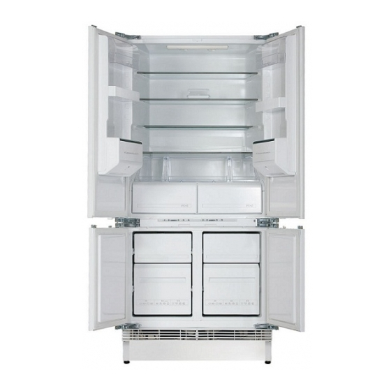
Page 10: The Fully Integrated 3-Zone Fridge-Freezer
H8-420-03-01Ä The fully integrated 3-zone fridge-freezer The various zones A - Refrigerator B - 0 °C zone C - Freezer For internal use only... - Page 11 H8-420-03-01Ä Multi-zone appliances enable the customer to make use of 3 refrigeration zones for optimum storage of all types of food. The refrigeration sections in detail: Refrigeration section A: Here an ideal environment is created for the storage of fresh food. This section employs an evaporator made of an integrated aluminium sheet and the temperature is controlled by means of an adjustable thermostat on the operation panel.
-
Page 12: Technical Data
H8-420-03-01Ä Technical data: IK 458.1-4T IK 458.2-4T General features Dimensions HxWxD 190x86x55 cm 190x86x55 cm Gross capacity: Refrig./ freezer/ 0° zone 274 / 128 / 45 l 274 / 128 / 45 l Cooling: Refrig./ freezer/ 0° zone cyclical / **** / 0-3°C cyclical / **** / 0-3°C... - Page 13 H8-420-03-01Ä IK 458-2-2T IK 458-4-4T General features Dimensions HxWxD 190x86x55 cm 190x86x55 cm Gross capacity Refrig./ freezer/ 0° zone 266 / 96 / 28 l 266 / 96 / 28 l Cooling: Refrig./ freezer/ 0° zone cyclical / **** / 0-3°C cyclical / **** / 0-3°C Amount of cooling agent: R134a...
-
Page 14: Air Circulation
H8-420-03-01Ä Air circulation Freezer section: the air produced by the battery-driven evaporator is put into circulation by the fan, which is located above the battery. The air flows into the right-hand compartment of the freezer and flows out again through two slits. The temperature is controlled by the thermostat bulb which can be seen installed right above the battery. -
Page 15: System Components
H8-420-03-01Ä System components IK 458.1-4T, IK 458.2-4T, IK 458-2-4T 1. Lighting 10. Defroster - thermal switch 2. Thermostat sensor 11. Safety thermostat 3. Water drainage 12. Heating resistor of the evaporator 4. Flap thermostat 13. Battery evaporator 5. Cold storage unit 14. - Page 16 H8-420-03-01Ä IK 458-4-4T Compressor of the refrigerator section 12. Thermometer bulb of the refrigerator section Compressor of the freezer section 13. Flap thermostat Condenser of the refrigerator section 14. Flap thermostat bulb Drain pan 15. NTC probe of the electronic thermometer Battery-operated evaporator 16.
-
Page 17: Components Of The Refrigerator Section
H8-420-03-01Ä 3.4.1 Components of the refrigerator section (for IK 458.1-4T, IK 458.2-4T and IK 458-2-4T only) Thermostat The temperature in this section is regulated by means of a thermostat which is located behind the operation panel. The probe of this thermostat projects through a small tube embedded in foam into the inner area of the appliance at the point where the evaporator is fastened. -
Page 18: Components Of The 0 °C Zone (All Models)
H8-420-03-01Ä 3.4.2 Components of the 0 °C zone (all models) At the rear of the inner housing of this compartment there is a flap thermostat enclosed in a transparent protector. The sensor is fastened under the top of the inner housing. The thermostat opens up or blocks the entry of cold air from the freezer located below. -
Page 19: Components Of The Left Freezer Section (Ik 458.1-4T, Ik 458.2-4T, Ik 458-2-4T)
3.4.3 Components of the left freezer section (IK 458.1-4T, IK 458.2-4T, IK 458-2-4T) The various components of the system are located in the inner cavity. The following elements are fastened at the rear of the inner housing behind a protector:... - Page 20 H8-420-03-01Ä A safety thermal switch is connected to the evaporator. This switches both heating resistors off as soon as the evaporator reaches a temperature of more than +30 °C due to a malfunction. The +10 °C thermostat switch first switches off the heating element on the battery evaporator. Thermal switch >...
-
Page 21: Components Of The Right Freezer Section
H8-420-03-01Ä 3.4.4 Components of the right freezer section (IK 458.1-4T, IK 458.2-4T, IK 458-2-4T) The following elements are located on the side wall: The temperature probe, PTC, for the electric thermometer The cold storage unit The electronic thermometer An electronic board in the operation panel indicates the temperature in the freezer by means of 6 LEDs which light up in sequence. -
Page 22: Components Of The Freezer Section (Ik 458-4-4T)
H8-420-03-01Ä 3.4.5 Components of the freezer section (IK 458-4-4T) Battery-operated evaporator and fan The battery-operated evaporator cools extremely well in spite of the fact that it takes up little space. This is made possible because the surface of the evaporator has been enlarged with numerous aluminium ribs installed in a zinc serpentine tube. - Page 23 H8-420-03-01Ä Temperature switch Two temperature switches with direct contact to the battery cut off the power supply to the defrost resistor in the case of: +10 °C, end defrost switch (cable color: grey); +40 °C, safety switch (cable color: black). Rubber valve The condensation water is let off through a silicone plastic valve located in the condensation water drainage hole.
-
Page 24: The Function Of The Defroster Heating Element (All Models)
H8-420-03-01Ä The function of the defroster heating element (all models) The heat generated by the defroster heating element has no influence on the temperature in the freezer or on that of the packages of food after the total thermal power has been consumed when the ice on the evaporator has been defrosted. -
Page 25: The Electronic Circuit
H8-420-03-01Ä The electronic circuit 3.6.1 Wiring diagram IK 458.1-4T, IK 458.2-4T, IK 458-2-4T Terminal board 10. Door switch of refrigerator Compressor refrigerator section 11. Door switch of freezer Compressor freezer section 12. ON/OFF switch Thermostat refrigerator section 13. Ventilator of evaporator Thermostat freezer section 14. -
Page 26: Circuit Diagram Ik 458.1-4T, Ik 458.2-4T, Ik 458-2-4T
H8-420-03-01Ä 3.6.2 Circuit diagram IK 458.1-4T, IK 458.2-4T, IK 458-2-4T Terminal board 10. Door switch of refrigerator Compressor refrigerator section 11. Door switch of freezer Compressor freezer section 12. ON/OFF switch Thermostat refrigerator section 13. Ventilator of evaporator Thermostat freezer section 14. -
Page 27: Wiring Diagram Ik 458-4-4T
H8-420-03-01Ä 3.6.3 Wiring diagram IK 458-4-4T PNC code 925780652 00 925780652 03 925780652 01 925780652 04 925780652 02 Terminal board 16. Door switch of freezer Compressor of the refrigerator section 19. ON/OFF switch Compressor of the freezer section 24. Fan Protective motor switch 25. -
Page 28: Circuit Diagram Ik 458-4-4T
H8-420-03-01Ä 3.6.4 Circuit diagram IK 458-4-4T PNC code 925780652 00 925780652 01 925780652 02 925780652 03 925780652 04 Terminal board 16. Door switch of freezer Compressor of the refrigerator section 19. ON/OFF switch Compressor of the freezer section 24. Fan Protective motor switch 25. -
Page 29: The Electronics
H8-420-03-01Ä 3.6.5 The electronics PRINTED CIRCUIT INPUT CONTACTS NEUTRAL PHASE SUPER PROBE ELECTRONIC THERMOMETER (PRINTED CIRCUIT 1.6 mm FR2 YO SUPER SUPER ON/OFF ALARM SWITCH PTC probe Input fast freeze - yellow LED (contact no. 1 on the printed circuit board) Phase voltage (contacts no. -
Page 30: Properties Of The Ntc Probe
H8-420-03-01Ä Properties of the NTC probe Conversion chart For internal use only... -
Page 31: Disassembling The Individual Components
H8-420-03-01Ä Disassembling the individual components 3.8.1 Components in the vicinity of the operation panel (IK 458.1-4T, IK 458.2-4T and IK 458-2-4T) Operation control lamp Alarm display Electronic thermometer Fast freeze display (S) Button of main switch Button of freezer thermostat and fast... -
Page 32: Components In The Refrigerator Section
H8-420-03-01Ä The electronic board If the board of the electronic timer is to be removed, first of all remove the thermostat of the freezer, which prevents the board from falling out, and then unscrew the two screws fastening the holder to the front of the operation panel. - Page 33 H8-420-03-01Ä This makes the following elements accessible: Thermal switch Timer (not for IK 458-4-4T, see page 16) Thermostat sensor Battery evaporator Heating resistor of the evaporator Heating resistor of the water duct The various electric components of the compartment are connected to a terminal board in the interior of the timer housing.
-
Page 34: Components Of The Compressor Cavity
H8-420-03-01Ä Defroster resistor - Battery evaporator Unscrew the screws fastening the evaporator to the rear wall of the freezer section. If it should be necessary to push the battery evaporator towards the front, press on the suction pipe from the back. The heating resistor is inserted into the hollow grooves of the battery blades. -
Page 35: Accessibility Of The Component Parts (Ik 458-4-4T)
H8-420-03-01Ä Accessibility of the component parts (IK 458-4-4T) 3.9.1 Freezer section Proceed as follows in order to access the freezer section component parts: Turn the fastening devices as shown in the illustration and remove the baskets from the holders. Remove the three screws of the back panel and remove it sideways. For internal use only... -
Page 36: Removing The Control Panel
H8-420-03-01Ä 3.9.2 Removing the control panel Proceed as follows in order to access the control panel component parts: Secure the switches of the interior lighting lamps in the lower and upper parts of the control panel. To do so, press the switches and turn them 45°. Remove the 5 screws with which the control panel cover is fastened. -
Page 37: Timer
H8-420-03-01Ä 3.9.5 Timer The timer is located in the casing on the right bottom corner of the appliance (under the lower hinge of the right-hand door of the freezer). Use a screw driver to turn the camshaft (clockwise only) in order to switch over the switch for contacts 3-4 and 3-2. -
Page 38: Defrost Resistor
H8-420-03-01Ä If the timer shaft is turned clockwise with a screwdriver, two engaging sounds will be heard. These indicate that the contacts have been closed. As seen in the illustration (the position indicated in which the engaging sounds can be heard is not an exact position), there is a minimal distance between the first engaging sound and the second sound, while the distance between the second and the first engaging is longer: Please note:... -
Page 39: Installation
H8-420-03-01Ä 3.10 Installation 3.10.1 Adjusting the height The appliance can be adapted to the height of the other kitchen units since the height can be set at 820 mm or at 870 mm. Prior to installing the appliance, set the height of the rear wheels and feet. The initial height is set at 820 mm. - Page 40 H8-420-03-01Ä Lean the panels onto the appliance. Fasten the rear angle, taking into consideration a depth of 900 mm for the depth of the panels and the outer dimensions of the kitchen unit. Fasten the panels at the front. If the thickness of the panels is less than 20 mm, the compensation discs A supplied are to be inserted.
- Page 41 H8-420-03-01Ä Tighten the screws and remove those in the vertical long hole. Check the vertical positioning of the front panels and adjust if necessary. Ensure that the front panels are level by loosening the screws of the inserts and using the compensation devices provided for this purpose.
-
Page 42: 3.10.3 Installing The Appliance
H8-420-03-01Ä 3.10.3 Installing the appliance Position the appliance as intended. Fasten it to the wall with an angle provided especially for this purpose. Do not cover the top of the appliance in order to enable the air to circulate better. Should a kitchen unit be installed above the appliance, it is to be fastened 50 mm from the wall and the distance to the ceiling must be at least 50 mm. -
Page 43: 3.10.4 Attaching The Base
H8-420-03-01Ä 3.10.4 Attaching the base Height adjustment H = 820 For a base of 140 to 170 mm, make an opening as shown. If the base is higher than 100 mm and lower than 140 mm, cut the compensation cover piece accordingly and mount it between the base and the ventilation grid with the snap fastening underneath the grid. -
Page 44: Ik 458.2 - 4T - Distancers For The Door Panels With Filling
H8-420-03-01Ä 3.11 IK 458.2 - 4T - Distancers for the door panels with filling Door panels upper left Door panels upper right (viewed from the rear) (viewed from the rear) 1051 mm 1000 mm 76.5 mm 25.5 mm 25.5 mm Door panels lower left Door panels lower right 76.5 mm...
Need help?
Do you have a question about the IK 458.1-4T and is the answer not in the manual?
Questions and answers