Table of Contents
Advertisement
Installation & Programming Manual
Getting Started
● Prepare door, per additional instructions (included) before installing unit.
● IMPORTANT: Read instructions completely before beginning installation.
● Refer to "Quick Reference" area and illustrations to identify components.
Use the checklist below to assure completion of important steps.
□ ATTACH CONNECTOR ..........................................
□ RUN "BOLT DIRECTION" DETERMINATION .......
□ PROGRAM CODE(S) .............................................
□ VERIFY OPERATION .............................................
Interior
Cover
Mounting
Screws
Program
Button
Mounting
Holes
Turnpiece
Copyright © 2010 Baldwin Hardware Corporation
Quick Reference
Interior
Assembly
Mounting
Plate
Latch
Adapter
Settings
Switch
Panel
LED
Interior
Assembly
Baldwin Keyless Entry Deadbolt Manual PK.9008 / 02/10
Section 5
Section 8
Section 9 a, b, c
Section 9 d
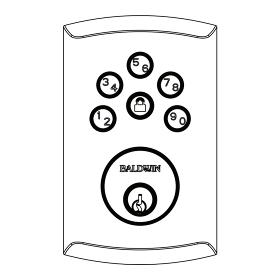
Exterior
Assembly
Cylinder
Lock Button
Keypad
Cylinder
Exterior
Assembly
1
Advertisement
Table of Contents

Related Manuals for Baldwin 8252 Series


Summary of Contents for Baldwin 8252 Series
- Page 1 Mounting Assembly Plate Interior Cover Mounting Cylinder Screws Latch Adapter Lock Button Settings Switch Program Panel Button Keypad Mounting Holes Cylinder Turnpiece Exterior Interior Assembly Assembly Baldwin Keyless Entry Deadbolt Manual PK.9008 / 02/10 Copyright © 2010 Baldwin Hardware Corporation...
- Page 2 1. Install latch and Strike. Fig. 2 Fig. 1 a. Determine your backset, see figure 1. (Note: Latch is shipped in the 2-3/8” back set.) Latch is shown in the upright position b. Extend bolt. If a 2-3/4” (70mm) backset is required adjust latch as shown.
- Page 3 Slide wires through the notch until mounting plate sits flush against door. d. Making sure that exterior assembly and cylinder are pressed flush against exterior door, with Baldwin cylinder logo horizontal, insert mounting bolts and tighten. e. Check the vertical alignment Fig.
- Page 4 5. Continued..b. For easier orientation, view the alignment of connection from the top of the interior assembly. c. Once aligned, push the connector in firmly to connect. 6. Install Interior Assembly. a. Making sure wires are clear of pinching and wire harness is routed as shown, place the interior assembly on door, aligning torque blade inside the turnpiece shaft.
- Page 6 8. Continued..a. Press and hold the “LOCK” button on the exterior keypad, while fully in- TURNPIECE serting the battery pack into the interior assembly (the tab on the pack must face out - see illustration). Hold down lock button until you hear 2 beeps (about 20 seconds).
- Page 7 9. Continued..d. Extend the bolt by pressing the “LOCK” button and re-enter the code to test. The bolt should retract to the unlocked position. If it does not unlock, repeat steps (a) through (c). Programming the 2nd user code. a.
- Page 8 11. Low Battery Indicators. 1. The interior LED ● Regardless of switch #1 position, under “Low Battery” condition - red LED will flash every 5 seconds. 2. The exterior Keypad (when switch #3 is OFF). ● After a correct code is entered, the keypad will flash red multiple times for approximately 3 seconds.
- Page 9 13. Frequently asked Questions (FAQs). Q: I just completed the installation of a Keyless Entry Deadbolt unit on my door; I am unable to operate it manually, although I checked for smooth bolt operation during installation. What should I A: You need to run the “Bolt Direction” routine again; allow the process to run to completion see Section 8 in User’s Manual.
Need help?
Do you have a question about the 8252 Series and is the answer not in the manual?
Questions and answers