Table of Contents
Advertisement
Product name:
Hardware version:
The unit must undergo a safety check at annual intervals in accordance with the national statutory regulations. Please follow these test
instructions. All tests must be done with fully functional and calibrated test equipment and by technicians trained in the service / maintenance
of electrical medical devices. Record the test results in the "safety check report" for reference in future tests and provide the user of the unit
with a signed report. If the unit fails to meet any of the checks, contact the manufacturer.
During service / maintenance take care of the different hardware versions which may be applicable (see below).
The hardware version of the unit can be identified by the serial number which can be found on the type plate at the back side of the unit. The
table below shows the serial number range to identify the hardware version.
Hardware version
Serial number (SN)
30 ... 31
A22701LE01.0001 ... A58702LE01.9999
32 ... ≥ 35
1000-1001 ... 6172-9999
From hardware version 35 the serial number itself includes already the hardware version. This code was introduced for units manufactured
since February 2005.
Example:
1234 W35 -567
Hardware version
Recommended test equipment and accessories
Electrical safety tester (Example: Unimet 1000 ST, Bender)
Electrosurgical analyzer (Example: QA-ES, Metron)
Load resistor 100 Ω, 25 W (or more), 5 % tolerance, low inductive part, short time load
Connection cables, HF-output (banana) to electrosurgical analyzer or load resistor
Power cord
Footswitch
© Celon AG
,
Issue date: 01.09.2008
SCI.991007-1.4
Safety Check
Instruction.doc
Safety Check Instruction
CelonLab ENT (100...120 V~)
30
REF no.: WB991007
LAB991.025.007
Page 1 / 9
Advertisement
Table of Contents

Related Manuals for Olympus CelonLab ENT


Summary of Contents for Olympus CelonLab ENT
- Page 1 Safety Check Instruction Product name: CelonLab ENT (100...120 V~) REF no.: WB991007 30 Hardware version: LAB991.025.007 The unit must undergo a safety check at annual intervals in accordance with the national statutory regulations. Please follow these test instructions. All tests must be done with fully functional and calibrated test equipment and by technicians trained in the service / maintenance of electrical medical devices.
- Page 2 Safety Check Instruction 1. Inspection of the unit and the accessories Procedure Accompanying documents are present and legible: - Instructions for Use - EMC-Guidelines - final test report (incl. test protocols according to the final test report) - optional (depending on the country): medical device information (“Medizinproduktebuch”) Labels present and legible: “Unit is defibrillator-safe”...
- Page 3 Safety Check Instruction Procedure Sample of symbol: Connection for equipotential bonding Visible on the back of the unit (see fig. 1) Samples of label for power fuses: Visible on the back of the unit (see fig. 1) Sample of label for volume switch: SPEAKER VOLUME Visible on the back of the unit (see fig.
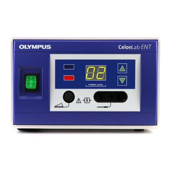
- Page 4 Safety Check Instruction Fig. 1: Sample of the backside of the CelonLab ENT power control unit Fig. 2: Sample of the front panel of the CelonLab ENT power control unit © Celon AG Page 4 / 9 Issue date: 01.09.2008 SCI.991007-1.4...
- Page 5 Safety Check Instruction 2. Display function check Procedure Test accessories: Power cord Connect the unit via power cord with a rated supply voltage. Switch on the unit and wait several seconds until the power level display shows “1”. Press the “UP“-button of the power setting (increasing the power) ten times. The power level display has to be increased by 1 per step until “10”...
- Page 6 Safety Check Instruction HF-output 2 HF-output 1 Fig. 3: Sample of the front panel of the power control unit showing the HF-outputs. 4. Valid resistance range Procedure Test equipment: Electrosurgical analyzer (Example: QA-ES, Metron) Connection cables, HF-output (banana) to the electrosurgical analyzer Test accessories: Power cord Footswitch Connect the unit via the power cord with a rated supply voltage.
- Page 7 Safety Check Instruction Procedure Upper shut off limit The following signals have to occur with a load resistor of 325 Ω (normal function of the unit): The blue LED (signal lamp “power output”) glows. The red LED (signal lamp “resistance too low”) is dark. A high frequency continuous signal is audible.
- Page 8 Safety Check Instruction 6. Earth resistance (according to IEC 60601-1 and IEC 62353) Procedure Test equipment: Electrical safety tester (Example: Unimet 1000 ST, Bender) Test probe Test accessories: Power cord Footswitch Connect the unit with an electrical safety tester according to the tester’s instructions for use and measure the following parameters against metal parts which can be touched: ≤...
- Page 9 Safety Check Instruction 8. Inspection label Procedure Cover or exchange an inspection label (as shown below) at the enclosure back of the unit and mark the due date of the next periodic safety check (month/year). The unit must undergo a safety check at annual intervals.
Need help?
Do you have a question about the CelonLab ENT and is the answer not in the manual?
Questions and answers