
Related Manuals for Toa IP-100XI


Summary of Contents for Toa IP-100XI
- Page 1 User’s Manual Power Amplifier Network Module IP-100XI Thanks for your purchase of TOA products IP-1000 series. Please read the manual carefully to ensure the machine operating in long time and fault-free. TOA Coporation...
- Page 2 Chapter 1 Safety Precaution...
-
Page 3: Chapter 1: Safety Precaution
Chapter 1: safety precaution Please abide by the warning and the relevant safety tips. Please take this manual in convenient place after you reading the guide for future reference. Warning The sign means there is potential safety hazard, when operate wrong may result in death or serious injury. - Page 4 Chapter 2 Products Description...
-
Page 5: Chapter 2: Products Description
2.1Summary 2.1Summary IP-100XI is a power amplifier network module, which can be installed in the specific amplifier product to add in the network functions, it can receive broadcast from other terminals and servers and it supports system setting via browser. -
Page 6: Interface Description
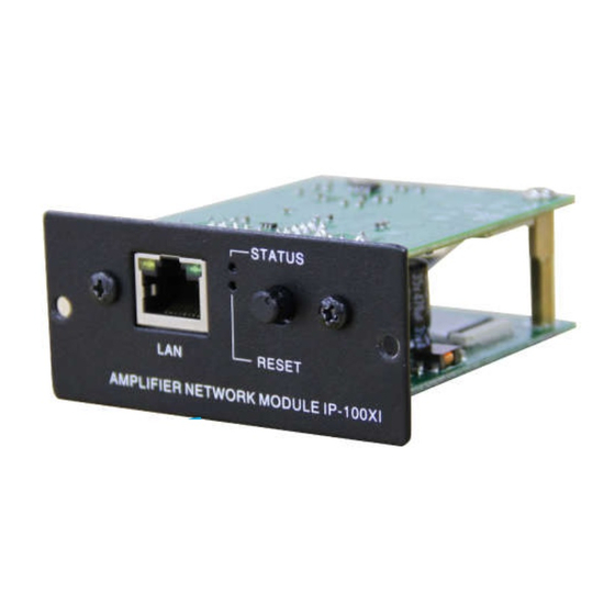
Chapter 2: Products Description 2.2 Interface Description ①LAN: network interface ②STATUS: status indicator light Online: the green light always be ON; Offline: the red light flash slowly; Receiving broadcast: the green light flash quickly; Updating firmware: both green and red light are flash quickly. ③RESET: pressing the key to restore factory defaults IP (or update firmware), broadcasting IP. - Page 7 Chapter 2: Products Description 2.2 Interface description Interface Remarks Description Power input, nominal input DC24V/150mA,the maximum range +24V DC15~30V Reference to the power input GNDA Reference to the audio signal Amplifier audio signal input,1Vrms/600Ω, imbalance. SIG_AMP Reference to the control signal Amplifier mute control output: triode collector open circuit output, MUTE_OUT broadcast open is for low level, broadcast close is for high resistance.
- Page 8 Chapter 3 Wiring...
-
Page 9: Chapter 3: Wiring
Chapter 3: Wiring 3.1 Wiring Diagram 3.1 Wiring diagram J4 interface: reserved interface. -
Page 10: Installation Description
Chapter 3: Wiring 3.2 Installation Description 3.2 Installation Description Using screws to fix IP amplifier module in the slot, as the following picture. - Page 11 Chapter 3: Wiring 3.3 Reference Size 3.3 Reference size(unit: mm)
- Page 12 Chapter 4 System setting by browser...
-
Page 13: Chapter 4: System Setting By Browser
Chapter 4: System Setting by Browser 4.1 Entering into browser 4.1 Entering into browser Step 1: Please input IP address of the power amplifier network module (factory defaults is 192.168.1.101), then press Enter. Step 2: Please input the user name and password in the login window of the Web page (the defaults is admin). -
Page 14: Network Parameters
Chapter 4: System Setting by Browser 4.2 Network parameters 4.2 Network parameters Identify the unique number of the speaker and it cannot be repeated with Device number other terminals or hosts. IP address IP address of amplifier module The defaults port number is 2046, please do not modify it if not in specially Device port situation. -
Page 15: Audio Parameters
Chapter 4: System Setting by Browser 4.3 Audio parameters 4.3 Audio parameters Broadcast coding, PCM means no data be compressed, ADPCM means Coding mode packed data (low network data value), display according to the server configuration. Line input volume Reserved Broadcasting Amplifier sampling rate in broadcasting(8000Hz,22050Hz). -
Page 16: Web Management
Chapter 4: System Setting by Browser 4.4 WEB management 4.4 WEB management You can modify the account number and password of the login Web page in the Web management parameters. - Page 17 Chapter 4: System Setting by Browser 4.5 Restarting device 4.5 Restarting device User can click “restart device” to restart the device.
-
Page 18: Resetting To Defaults
Chapter 4: System Setting by Browser 4.6 Resetting to defaults 4.6 Resetting to defaults Resetting defaults: all the parameters will reset to defaults. -
Page 19: Firmware Upgrade
Chapter 4: System Setting by Browser 4.7 Firmware upgrade 4.7 Firmware upgrade Clicking into the firmware upgrade mode to enter the firmware upgrade interface. Click browse in the upgrade firmware interface, please select the correct upgrade files, click on "upgrade", it will automatically restart after completed the upgrade. -
Page 20: System Log
Chapter 4: System Setting by Browser 4.8 System log 4.8 System log It can browse the amplifier module log in the Web page, click “delete all logs” can delete all the logs in the Web page. - Page 21 Chapter 5 Appendix...
-
Page 22: Chapter 5: Appendix
Chapter 5: Appendix 5.1 Specification 5.1.1 Power amplifier network module IP-100XI IP-100XI Model DC24V Power Current consumption <85mA Control voltage≤DC30V,control electric current≤500mA. Relay NC contact Control voltage≤DC30V,control electric current≤500mA. Relay COM contact Control voltage≤DC30V,control electric current≤500mA. Relay NO contact 10BASE-T/100BASE-TX,automatic determination... - Page 23 TOA Corporation 201611...
Need help?
Do you have a question about the IP-100XI and is the answer not in the manual?
Questions and answers