Table of Contents
Advertisement
Quick Links
Advertisement
Table of Contents

Subscribe to Our Youtube Channel
Related Manuals for Unical TRISTAR 3G


Summary of Contents for Unical TRISTAR 3G
- Page 1 TRISTAR 3G INSTALLATION AND MAINTENANCE INSTRUCTIONS 00334572 - 09/15 rev. 1...
-
Page 2: Table Of Contents
3.8 Condensation drainage ..................................... 18 3.9 Furnace door: adjustment, opening, closing ............................19 3.9.1 TRISTAR 3G 110÷TRISTAR 3G 380 boilers ............................. 19 3.9.2 TRISTAR 3G 500÷TRISTAR 3G 840 boilers ............................ 19 3.9.3 TRISTAR 3G 1100÷TRISTAR 3G 3000 boilers ..........................20 3.9.4 Important note .................................... -
Page 3: General Information
The appliance is intended to operate in hot air circulation heating systems. Any other use must be considered improper. UNICAL shall not be held liable for any damage resulting from improper use; in this case the user is fully responsible for the risk. -
Page 4: Safety Warnings
General Information 1.5 - SAFETY WARNINGS ATTENTION! The appliance must be installed, adjusted and maintained by professionally qualified personnel, in com- pliance with standards and provisions in force. Incorrect installation can cause damage to persons, ani- mals and objects for which the manufacturer cannot be held responsible. DANGER ! NEVER attempt to perform maintenance or repairs on the boiler on your own initiative. -
Page 5: Technical Data Plate
The serial number of the boiler is on the riveted plate on the front plate of the body: lower right front for models between TRISTAR 3G 110 and TRISTAR 3G 1900 upper right front for models between TRISTAR 3G 2300 and TRISTAR 3G 3000. -
Page 6: General Warnings
Keep the booklet with care for further consultation. Any repairs must be performed solely by personnel authori- sed by Unical using original spare parts only. Failure to com- Installation and maintenance must be performed in com- ply with the above can jeopardise the safety of the appliance. -
Page 7: Technical Features And Dimensions
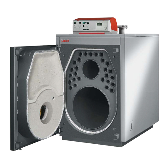
2.1 - TECHNICAL FEATURES The top part of the shell is fitted with hooks for lifting the boiler. TRISTAR 3G boilers are of horizontal cylindrical type with fla- me inversion in the furnace and third flue gas pass in tubes. -
Page 8: Dimensions
Technical features and dimensions 2.3 - DIMENSIONS - TRISTAR 3G 110÷150 T1-T3-T2 n°4 "L" fig. 2 1 Panel board T1 Heating flow T5 Chimney connection 3 Smoke chamber cleaning door T2 Heating return T6 Burner connection 4 Flame control warning light... - Page 9 Technical features and dimensions TRISTAR 3G 185÷380 T1-T3-T2 fig. 4 1 Panel board T1 Heating flow T5 Chimney connection 2 Burner connection flange T2 Heating return T6 Burner connection 3 Smoke chamber cleaning door T3 Expansion vessel connection T7 Condensation drain...
- Page 10 Technical features and dimensions TRISTAR 3G 500÷840 T1-T3-T2 fig. 6 1 Panel board T1 Heating flow T5 Chimney connection 2 Burner connection flange T2 Heating return T6 Burner connection 3 Smoke chamber cleaning door T3 Expansion vessel connection T7 Condensation drain...
- Page 11 Technical features and dimensions TRISTAR 3G 1100÷1900 T1-T3-T2 fig. 8 1 Panel board T1 Heating flow T5 Chimney connection 2 Burner connection flange T2 Heating return T6 Burner connection 3 Smoke chamber cleaning door T3 Expansion vessel connection T7 Condensation drain...
- Page 12 Technical features and dimensions TRISTAR 3G 2300÷3000 fig. 11 1 Panel board T1 Heating flow T5 Chimney connection 2 Burner connection flange T2 Heating return T6 Burner connection 3 Smoke chamber cleaning door T3 Expansion vessel connection T7 Condensation drain...
-
Page 13: Operating Data As Per Uni 10348
2.4 - OPERATING DATA ACCORDING AS PER UNI 10348 TST 3G 110 TST 3G 150 TST 3G 185 TST 3G 240 TST 3G 300 TST 3G 380 TST 3G 500 TST 3G 630 GAS-FIRED Nominal heat output 81,7÷109 112,5÷150 138,75÷185 180÷240 225÷300 285÷380... -
Page 14: Installation Instructions
Technical features and dimensions INSTALLATION INSTRUCTIONS 3.1 - GENERAL WARNINGS ATTENTION! In rooms with the presence of aggressive vapours or dust, the appliance must operate ATTENTION! independently from the air inside the instal- This boiler is intended solely for the use for lation room! which it was expressly designed. -
Page 15: Installation Standards
(and subsequent modifications), Italian Presidential Decree well as applicable technical standardsi. n°551 of 21.12.1999. TRISTAR 3G is a steel boiler which can be combined with Regulation with amendments to Italian Presidential Decree. air-blown burners fired by gas of category II2H3+. -
Page 16: Handling
(dimensions in mm); in any case, never less than 1300 mm xx = see instructions to the side. 3.5 - BURNER The burners operating with the TRISTAR 3G boilers must namely combustion chamber backpressure, refer to zero pres- have the EC certification and comply with: sure at the base of the chimney. -
Page 17: Installing The Burner
TRISTAR 3G 1100÷1320 TRISTAR 3G 1600÷1900 fig. 15 TRISTAR 3G 2300 TRISTAR 3G 2650 - 3000 DIMENSIONS OF BURNER BLAST TUBE 3.5.2 - INSTALLING THE BURNER The burner must be mounted to the door of the boiler guaran- the support plate and put back afterwards. -
Page 18: Flue Connection
The supplier will have no contractual or extra- contractual liability for damage caused due to The TRISTAR 3G boiler can be attached to the chimney in incorrect installation and use and anyway fai- different ways; straight pipes or elbows can be used to exit... -
Page 19: Furnace Door: Adjustment, Opening, Closing
Technical features and dimensions 3.9 - FURNACE DOOR: ADJUSTMENT, OPENING AND CLOSING IMPORTANT - The door of the boiler must be opened when it is cooled off - The door fibre is easy to replace and is covered by a two- to avoid damaging the fibre due to thermal shock. -
Page 20: Tristar 3G 1100÷Tristar 3G 3000 Boilers
Technical features and dimensions 3.9.3 - “TST 3G 1100÷TST 3G 3000” BOILERS For all these models, the door is hinged and fixed according to the layout in fig. 20. In these cases, the two hinges on the left are normally used as rotation hinges (from right to left) while the two on the right are used as closing hinges. -
Page 21: Connecting Boiler To System
Technical features and dimensions 3.10 - CONNECTING BOILER TO Connection of expansion vessel SYSTEM TRISTAR 3G boilers are suitable for operating with forced wa- ter circulation both with the expansion vessel opened or clo- Attention! sed. Before connecting the boiler to the heating... -
Page 22: Connecting Gas
Technical features and dimensions check the pressure gauge until pressure reaches appro- Attention! ximately 1 bar. Make sure that there are no mechanical ten- close the filling tap and bleed air once again through the sion points while connecting gas to avoid the radiator air release valves. -
Page 23: Packaging
Technical features and dimensions 3.13 - PACKAGING TRISTAR 3G boilers are supplied complete with the door - ceramic fibre cord to insulate between burner blast tube and smoke chamber assembled, while the casing and insu- and door. lation are included in separate cardboard package(s). -
Page 24: Assembling Casing
Technical features and dimensions 3.14 - ASSEMBLING CASING TRISTAR 3G 110÷380 4 11 Assembly sequence (Ref. fig. 21) fig. 21 A) Mount the insulation (pos. 1) of the boiler body and secure Close the cover of the electric control board. - Page 25 Technical features and dimensions 1 Thermometer probe 2 Working thermostat probe 3 Safety thermostat probe 4 Minimum thermostat probe 5 Safety spring 6 Probe bulb holders fig. 22...
- Page 26 Technical features and dimensions TRISTAR 3G 500÷840 3b / 4b fig. 23 Assembly sequence (Ref. fig. 23) A) Mount the insulation (pos. 1) of the boiler body and secure Fasten the 4 countersunk screws (pos. 7) to the two sides the 2 edges with the elastic straps (pos.
- Page 27 Technical features and dimensions the burner and to any pumps, etc. G) Fix the installation and boiler data plate (pos.13) to the side Close the cover of the electric control board. panel after having degreased the relevant part with the spe- Guide the burner plug through the side plate (pos.
- Page 28 Technical features and dimensions TRISTAR 3G 1100÷1600 fig. 24 4a 5...
- Page 29 Technical features and dimensions TRISTAR 3G 1900 fig. 25 Assembly sequence (Ref. fig. 25) E) Insert into the conduits the bulbs of the instruments as indi- A) Mount the insulation (pos. 1) of the boiler body and secure cated in fig. 27 and wire the panel board to the power line, the 2 edges with the elastic straps (pos.
- Page 30 The hole-covering panel pos. 4 is already mounted. after having degreased the relevant part with the specific C) Position the right side panels (pos. 6 and 3) with the lower solvent. The plates are included in the document envelope. TRISTAR 3G 2300 - 3000 fig. 26...
- Page 31 Technical features and dimensions Probe insertion sequence Following this sequence, insert the probes of the instruments in the bulb holder/s on the top of the boiler (Ref. Fig. 27): of the thermometer (pos. 1), of the working thermostat (pos. 2) of the safety thermostat (pos.
-
Page 32: Electrical Connections
Technical features and dimensions 3.15 - ELECTRICAL CONNECTIONS 230V electric power supply connection General warnings The electrical connections are illustrated in chap. 3.16, 3.17, 3.18, 3.19, 3.20. The electrical safety of the appliance is guaranteed only when it has been properly connected to an efficient earthing system The boiler installation requires a connection to a 230 V - 50 carried out as intended by safety standards in force: pipes of Hz electric mains: this connection must be properly carried... -
Page 33: Standard Panel Board
Technical features and dimensions 3.16 - STANDARD PANEL BOARD The main switch 11 powers the board and the equipment The differential between the two contacts is 6°C (not adjusta- connected to it. ble). The switches 12 and 13 in turn cut power to the burner and to The minimum thermostat, which can only be accessed after the system pump. -
Page 34: Hydraulic And Electrical System Connection
TA = room thermostat The standard panel board of the TRISTAR 3G boiler automa- The panel is set up to manage dual-stage or modulating tically switches the burner off when the temperature in the burners. - Page 35 TO THE 7-POLE SOCKET OF THE BURNER POWER SUPPLY 230V ~ 50Hz POWER SUPPLY 230V ~ 50Hz TRISTAR 3G BOILER CALDAIA TRISTAR 3G DOMESTIC HOT WATER PRODUCER fig. 31 NOTE: With absorption beyond 4A, place adequate contactors between the panel board and the loads...
-
Page 36: Optional Panel Board
Technical features and dimensions 3.18 - OPTIONAL PANEL BOARD The main switch 11 powers the board and the equipment Eventual operation of the second stage of the burner will be connected to it. managed by the heat control. Switches 12 and 13 control the burner and the mixed zone The default setting of the heating controller stops the system system pump. -
Page 37: Layout Of Probe Connection On Heating Controller
Technical features and dimensions 3.19 - LAYOUT OF PROBE CONNECTION ON HEATING CONTROLLER CODE 30680 fig. 34 The heating controller probes (boiler, storage tank, external, Should ambient probes be mounted (optional), the room tem- flow) are included in the supply; the ambient probes 1 and 2 perature will only be determined with the boiler curve set by are optional;... - Page 38 Technical features and dimensions PARAMETERS PROGRAMMABLE BY TECHNICIAN AND PROTECTED BY ACCESS CODE INSTALLATION Description Value range Default Individual values CODE NUMBER 0000 - 9999 ENTRY CODE NUMBER (adjustment) 0000 - 9999 0000 BUS ID 1 1 1 1 1 (00), 01 - 15 BUS ID 2 2 2 2 2 (00), 01 - 15...
- Page 39 Technical features and dimensions HEATING CIRCUIT 1 Description Value range Default Individual values HEATING CIRCUIT FUNCTION 00 - 04 PUMP MODE 00 , 03 MIXER OPEN 5 - 25 (not in hot water circuit) MIXER CLOSED 5 - 25 (not in hot water circuit) MAX FLOW TEMPERATURE 20 °C - 110 °C 80 °C...
-
Page 40: Hydraulic And Electric System Connection With Optional Panel Board
DOMESTIC HOT fig. 35 WATER PRODUCER The optional panel board of the TRISTAR 3G boiler automati- With this layout configuration, the DHW storage tank loading cally switches the burner off when the temperature in the boi- pump will have the priority over the heating system pump. - Page 41 ROOM PROBE 2 (FBR1) POWER SUPPLY 230V ~ 50Hz POWER SUPPLY 230V ~ 50Hz CALDAIA TRISTAR 3G TRISTAR 3G BOILER DOMESTIC HOT WATER PRODUCER NOTE: With absorption beyond 4A, place adequate contactors between the panel board and the loads fig. 36...
-
Page 42: Commissioning
230V - 50Hz; new owner and/or installer can access it. TRISTAR 3G boilers are forced circulation boilers: it is the system is filled with water (approximately 1 bar pres- therefore necessary to make sure that water circulates sure on the pressure gauge with the pump stopped);... -
Page 43: Adjustment Of Burner
Unical spare parts must be long life. used. Yearly maintenance of the appliance is man- datory in compliance with applicable lawse. -
Page 44: Boiler Body Maintenance
Inspections and maintenance Boiler body maintenance Checking status of gaskets and insulation fibres The insulation fibre of the door can show Danger! cracks after a short time of operation; this howe- Before performing any maintenance, make ver does not reduce its insulation capacity nor sure the boiler and its components have co- jeopardise its lifespan. - Page 45 Inspections and maintenance...
- Page 46 Inspections and maintenance...
- Page 47 Inspections and maintenance...
- Page 48 46033 casteldario - mantova - italia - tel. 0376/57001 (r.a.) - telefax 0376/660556 www.unical.eu - info@unical-ag.com Unical will not be held responsible for possible inaccuracies if due to transcription or printing errors. It also reserves the right to modify its products as deemed necessary or useful, without jeopardising their essential features.
Need help?
Do you have a question about the TRISTAR 3G and is the answer not in the manual?
Questions and answers