Table of Contents
Advertisement
Advertisement
Table of Contents

Related Manuals for Datafox PZE-MasterIV


Summary of Contents for Datafox PZE-MasterIV
- Page 1 Manual PZE-MasterIV Flexible data collection with method...
- Page 2 Datafox GmbH. The assertion of all rights in this respect is reserved to Datafox GmbH, especially in case of the grant of a patent. The handover of this documentation does not establish a claim to the license or the use of the soft- and hardware.
- Page 3 Datafox MasterIV, SW version xxx.pdf list as shown. The file is located on the Datafox DVD and for download on the homepage. Please also note the instructions in each chapter in the manual. The updates are available on our website under www.datafox.de download.
-
Page 4: Table Of Contents
3.5. Further Notices ......................6 3.6. Disposal.........................6 System Requirements / Hardware 4.1. System Structure ......................7 4.2. Requirements for Operating Datafox Devices ............7 4.3. Kompatibilität Compatibility ..................8 4.3.1. Firmware File Archive (*.dfz) ..................8 4.3.2. Datafox Devices and Device Firmware................8 4.3.3. Device Firmware and Device Setup ................8 4.3.4. - Page 5 RFID Reader ........................91 5.10. Fingerprint........................92 5.10.1. General Information ......................92 5.10.2. Operation ........................93 5.10.3. Teach-In........................94 5.10.4. Procedure ........................95 5.10.5. Process Variants......................96 5.10.6. Technical Data of the Fingerprint Module ..............97 5.11. Buzzer ..........................98 Technical Data index Manual PZE-MasterIV page V date: 29.08.2013 Version:04.02.04...
-
Page 6: For Your Safety
For Your Safety Safety Information for Datafox Products The device must only be operated according to the instructions given in the manual. Do no insert any foreign objects into the openings and ports. The device must not be opened. All maintenance work must only be performed by authorized specialists. -
Page 7: Introduction
Introduction Datafox data terminals have been developed to fulfill the requirements of modern personnel time recording where users have high demands concerning flexible and elegant design. Furthermore, the Datafox Embedded-Concept also covers access control. All relevant data can be recorded with modern technology and be transferred to the analysis software immediately. -
Page 8: Typography Of The Documentation
Due to technical development, illustrations, function steps, procedures and technical data may vary slightly. The Datafox device has been developed for the purpose of creating a flexible and easily inte- grated terminal for data recording serving for a great variety of applications. The device is robust and easy to use. - Page 9 Note: Due to DatafoxStudioIV, Datafox devices offer many functions and combinations of functions not all of which can be tested in the case of updates. This applies espe- cially to setups defined by you as customer.
-
Page 10: Intended Use And Environmental Protection Regulations And Notices
3.4. Maintenance / Repair Datafox devices are maintenance-free and must only be opened by authorized professionals. In case of defects, please contact your dealer or the Datafox service hotline. In order to remove impurities, only use a dry or at the maximum a slightly damped cloth. -
Page 11: Further Notices
The correct disposal of electrical and electronic equipment protects human life and the environment. For more information regarding the disposal of electrical and electronic equipment, please contact your local authorities or waste disposal companies. Manual PZE-MasterIV page 6 date: 29.08.2013 Version:04.02.04... -
Page 12: System Requirements / Hardware System Structure
4.2. Requirements for Operating Datafox Devices In order to operate the Datafox device, you need a 230 V power connection for the Datafox power supply. Depending on the main communication set, you need a corresponding transfer medium or connection cable. -
Page 13: Kompatibilität Compatibility
Device files (*.hex) of the MasterIV devices are delivered in a common firmware file archive. It has the file extension DFZ (stands for Datafox Zip). Now simply the firmware file archives (*.dfz) are in- dicated instead of the device files (*.hex). This applies to the DatafoxStudioIV and the DLL. The in- dication of device files (*.hex) is still possible. -
Page 14: Device Firmware And Communications Dll
A newer version of DatafoxStudioIV does not work with an older DLL. 4.3.6. DatafoxStudioIV and Device Setup With the DatafoxStudioIV, you create a device setup (application program) for the Datafox device. That means that in the setup only those functions were defined which were available in the Data- foxStudioIV version at the time of the setup creation. -
Page 15: Update / Downgrade
When performing a firmware downgrade the firmware has to be transmitted to the device twice. This has technical reasons. Errors shown on the display of the device after the first transfer can be ignored. Manual PZE-MasterIV page 10 date: 29.08.2013 Version:04.02.04... -
Page 16: Device
Keep in mind the message - FlashService - in the display of the device. It means that the live time of the flash memory according to the manufacturer instruction will be reached soon. Then the device has to be sent to Datafox for service. -
Page 17: Guideline For Commissioning
► Finishing installation of the device ► Setting the main communication Bios Menu 5.2.3. Troubleshooting during Commissioning ► Please see the FAQ on our website: http://www.datafox.de/faq-de.html. ► Tips: o Connection to the device cannot be set up via TCP/IP ... -
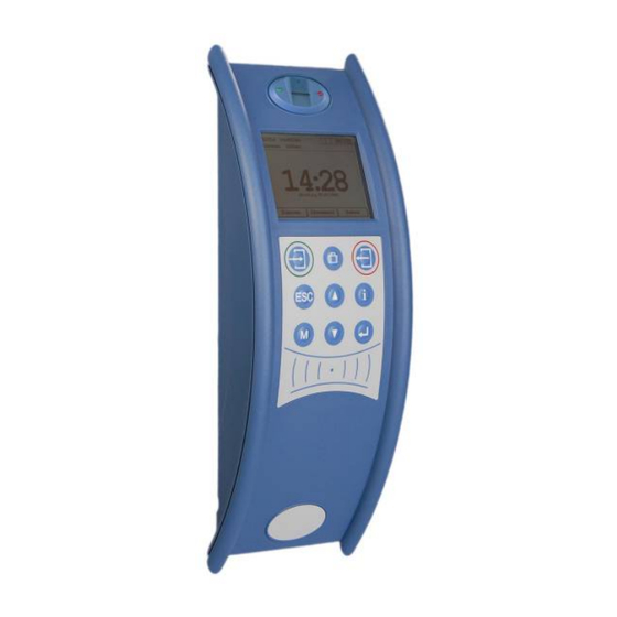
Page 18: Display And Operation
The buttons of the devices may only be pushed using fingers. Under no circumstances should the buttons be pressed by hard or pointy objects such as keys, transponders or coins. The keyboard of the PZE-MasterIV is structured as follows: finger scanner Keys for input sequence 1 –... -
Page 19: Key And The Combinations
Switching to main menu in operation mode PZE ESC key Changing pages e.g. at GV info screen Left arrow or right arrow Rebooting the device F1(1) + F2(2) + M(5) + ENTER (8) Manual PZE-MasterIV page 14 date: 29.08.2013 Version:04.02.04... -
Page 20: Display And Menu Bios
During transmission of a setup or updates the symbol „ Systemstop“ is shown. o On the left site in the Display: = read RFID = read barcode = to clock in = to clock out Manual PZE-MasterIV page 15 date: 29.08.2013 Version:04.02.04... -
Page 21: System Menu Bios
(select „yes“ when you send date to webserver via http, select „no” when you use the DFCom.dll or the program DatafoxStudioIV) tcp / ip (this is for setting TCP/IP address, port, gateway… ) Manual PZE-MasterIV page 16 date: 29.08.2013 Version:04.02.04... -
Page 22: Tcp/Ip Settings In The Bios-Menu
With the keys “check in or check out”, can you navigate in the 255.255.255.240 menu. The arrow keys use to change the value. 255.255.255.224 255.255.255.192 255.255.255.128 255.255.255.0 255.255.254.0 255.255.252.0 255.255.248.0 255.255.240.0 255.255.224.0 255.255.192.0 255.255.128.0 255.255.0.0 255.254.0.0 255.252.0.0 255.248.0.0 255.240.0.0 255.224.0.0 255.192.0.0 255.128.0.0 255.0.0.0 Manual PZE-MasterIV page 17 date: 29.08.2013 Version:04.02.04... -
Page 23: Rfid Menu
All segment values where the option "Auto increment" was set in the menu are increased by the increment value. When you have written all cards you can leave the menu by pressing ESC. The function increment: You must enable in the setup defaults. Manual PZE-MasterIV page 18 date: 29.08.2013 Version:04.02.04... -
Page 24: Installation Instructions Of The Pze-Master
Reading area of the transponder reader Power supply 24V 300 mA, Datafox Artikel-Nr.: 105108 If the device is mounted on a flush box and there is only one screw available, simply cut off the 230 volt plug and connect the wires to the screw terminal. -
Page 25: Installation On Detached Column
5.4.2. Installation on detached column The assembly occurs more than 3 points (Screws are enclosed). power supply 24V AC, 300 mA, Datafox Artikel number.: 105108 The management supply oc- curs, on this occasion, over the state foot. Manual PZE-MasterIV page 20... -
Page 26: Power Supply Of The Pze-Masteriv
5.5. Power supply of the PZE-MasterIV 5.5.1. Power supply with AC adapter In principle, only one voltage source may be connected to the PZE-MasterIV. Use a 24 V/ 300 mA AC/DC power supply unit for this. Power supply 24V AC,... -
Page 27: Connection
Data channel A Data channel B 24 V DC RS485 interface for access control Data channel A Data channel B 12 V DC out max. 150 mA TCP / IP RJ 45 SIM-kart Slott antenna Manual PZE-MasterIV page 22 date: 29.08.2013 Version:04.02.04... -
Page 28: Barcode Reader
5.6.2. Barcode Reader Attention: You can connect a bar code reader on the Datafox device, but the communication to PC not by rs232. Select in the Bios on the Device another interface than rs232. You can connect all bar code reader with rs232 connection. PZE-MasterIVPlease note the folder wiring for rs232. -
Page 29: Power Supply
5.6.3. Power Supply Caution: Only one voltage source must be connected to the PZE-MasterIV. Use a 12 – 24 V 300 mA AC/DC power supply for this purpose. At most one external load (e.g. a transponder reader for access control) may be supplied by this power supply via the RS485 interface. - Page 30 The following figure shows the connection of ground-referenced contacts. Observe the max. voltage of 30 V DC at the switching output and thus at the digital input of the PZE-MasterIV. This example displays the possibility of connecting a potential-free contact to the digital inputs.
-
Page 31: Digital Outputs
Observe the max. current of 2.0 A at 42 V AC or 30 V DC when connecting con- sumer units. This example displays the possibility of connecting an SPS with 24 V output (electricity of ca. 7 mA / port). Manual PZE-MasterIV page 26 date: 29.08.2013 Version:04.02.04... - Page 32 Ground D-IN3 Digital input 3 (10Hz) D-IN4 Digital input 4 (10Hz) D-IN5 Digital input 5 (10Hz) D-IN6 Digital input 6 (10Hz) A-IN1 Analog input 1 (0-10 V) A-IN2 Analog input 2 (0-10 V) Manual PZE-MasterIV page 27 date: 29.08.2013 Version:04.02.04...
-
Page 33: Communications
8. GPRS via Mobile phone network (with protocol HTTP1.1) 9. GSM via Mobile phone network with analog Modem 5.7.1. Communication via RS232 For a communication with a PZE-MasterIV over an RS-232 connection, the device has to be set for this communication in the system menu-BIOS (see chapter display Bios menu). -
Page 34: Conversion Of Rs232 To Rs485
8 pole connector. Anschluss des PZE-MasterIV per RS485 (Stiftleiste) Achtung: If the power supply of the PZE-MasterIV and the RS485 bus is established via PIN 1/4 direct voltage must be used. Manual PZE-MasterIV page 29... -
Page 35: Communication Via Tcp/Ip
If the device is to be connected directly to a PC via Ethernet, a crossover cable has to be used. Connection of the PZE-MasterIV via Ethernet Caution: Power over Ethernet (PoE) describes a process where network-compatible devices can be energized via the 8-core Ethernet-wire. -
Page 36: Transition From Tcp/Ip To Rs232 / Rs485 Via Com Server
Pin 15 - BUS B Pin 3 - BUS B Pin 3 - BUS B Pin 14 - BUS A Pin 1 - GND Pin 1 - GND Pin 7 - GND Transition from TCP/IP to RS485 Manual PZE-MasterIV page 31 date: 29.08.2013 Version:04.02.04... -
Page 37: Set-Up Of The Com Server Lantronix Uds 11
You are asked for a username and pass- word. Because the COM Server is in the state as delivered, no username or pass- word is set. Thus, make no entries and only confirm with “OK”. Manual PZE-MasterIV page 32 date: 29.08.2013 Version:04.02.04... - Page 38 2. The "Local Port" must be set to 8000 via the setting option "Connection". 3. Save your settings with "OK" and then "Apply Settings", otherwise they will not be taken over. Restart the COM Server and check the connection. Manual PZE-MasterIV page 33 date: 29.08.2013 Version:04.02.04...
-
Page 39: Communication Via Wlan
There are two possibilities to configure the match port. Either via the TCP/IP with the DeviceInstaller of Lantronix or via the RS232 using the tool WLANConfig and the DatafoxStudio (from version 04.01.06.xx on). DatafoxStudioIV Datafox Device RS232 WLANConfig RS232 RS232 Deviceinstaller von Lantronix COM Server Matchport TCP/IP WLAN Manual PZE-MasterIV page 34 date: 29.08.2013 Version:04.02.04... - Page 40 By now a long list of experimental protocols (OLSR, MIT RoofNet, B.A.T.M.A.N etc.) and several proposals for standardisation (Hybrid Wireless Mesh Protocol, 802.11s) as well as some commer- cial solutions (e.g. Adaptive Wireless Path Protocol from Cisco) were produced. Manual PZE-MasterIV page 35 date: 29.08.2013 Version:04.02.04...
- Page 41 CCMP (= Counter Mode with Cipher Block Chaining Message Authentication Code Protocol) or also Counter-Mode/CBC-Mac Protocol is, according to IEEE 802.11i, a cryptography algorithm. CCMP is based on the Advanced Encryption Standard (AES) and uses a 128-bit-key with a 48-bit-initialisator for answer query. Manual PZE-MasterIV page 36 date: 29.08.2013 Version:04.02.04...
- Page 42 It might be possible, that some special characters do not exist on for- eign keyboards. Manual PZE-MasterIV page 37 date: 29.08.2013 Version:04.02.04...
- Page 43 In that case the module can be configured again with the device installer of Lan- tronix. Another possibility is, to use the program WLANConfig by Datafox, which accesses to the device via RS232 and configures the MatchPort from there. An access to the MatchPort is always possible via RS232, provided that the main communication is set on RS232.
- Page 44 Encryption TKIP CCMP 64 Bit NO Key !!! TIP+WEP CCMP+TKIP 128 Bit CCMP+WEP TKIP TX-Key TIP+WEP Authentication : Authentication : Pre Shared Key (1) Open/None (0) Shared Key (1) Key & Key Type Manual PZE-MasterIV page 39 date: 29.08.2013 Version:04.02.04...
- Page 45 Datafox-Optionen ( eingebaute Module )wLAN, Matchport. With the help of this tool the COM servers Xport and MatchPort of the Datafox devices can be con- figured. The device installer accesses to the COM server via TCP/IP, the Datafox terminals via S232.
- Page 46 Via the button Select INI-File the dialogue is started. Here you can create new files or select a file, here data are logged on. On the INI file all settings of the TCP/IP and the WLAN are logged. Manual PZE-MasterIV page 41...
- Page 47 Via the button Terminal TCP/IP Settings the dialogue is started. The current firmware version of the MatchPort and the MAC-address are displayed. You can edit the other parameters, which are equal to those of the BIOS dialogue of the terminal and of the Datafox Studio. WLAN Settings The WLAN settings allow the editing of values, that were read out of the terminal and loaded inon a INI file or entered manually.
- Page 48 Via Write WLAN Config Config the data are loaded from the program into the device. Via Read Ini-File the data are loaded from the selected file into the program. Via Write Ini-File INI file the data are written from the program in the file. Manual PZE-MasterIV page 43 date: 29.08.2013 Version:04.02.04...
-
Page 49: Communication Via Usb
Caution: Note that the USB interface of the terminal is an USB type B, when communicating with the PZE-MasterIV . That means the terminal works in slave mode and therefore cannot manage other USB devices. You must install the USB device drivers and the USB serial converter drivers which are necessary to communicate via USB. - Page 50 Installation” in order to use the driver. In the Device Manager the entry for the Datafox USB serial port has been added. Via this COM port you can establish a connection to the MasterIV device with the DatafoxStudioIV or your own application using the DFComDLL.dll.
- Page 51 In addition to the main communication USB, it is possible to use an USB stick as data medium. Thus, you can read data records from a PZE-MasterIV and process them on a PC or create lists for the master data or the access control.
-
Page 52: Communication Via Modem
Time-out. The modem in which the terminal should be connected must be configured above the COM interface of a PC's. The in the following performed steps refer II“ mo- dems to tested and recommended „Devolo-MicroLink 56 K fun II.” Manual PZE-MasterIV page 47 date: 29.08.2013 Version:04.02.04... - Page 53 The configurations mentioned above are no guarantee for a connection. They are just based on experience and maybe have to be set to the different telephone systems. Configurations that are not listed here usually do not work. Manual PZE-MasterIV page 48 date: 29.08.2013 Version:04.02.04...
- Page 54 Connector Datafox-Device and Modem Bezeichnung Funktion DCD data carrier detect Träger erkannt RxD receive data Empfangsdaten TxD transmit data Sendedaten DTR data terminal ready DEE empfangsbereit GND ground Signalmasse DSR data set ready Betriebsbereitschaft RTS request to send Sendeanforderung CTS clear to send...
-
Page 55: Communication Via Cellular Network (Gsm Or Gprs/Gsm)
5.7.8. Communication via Cellular Network (GSM or GPRS/GSM) The PZE-MasterIV can be equipped with a cellular network modem. It enables the communication via cellular network. The antenna is located in the connection compartment of the device and can optionally be replaced by an external antenna if reception is bad. -
Page 56: Necessary Settings For Communication Via Cellular Network
For more information regarding the encryption of data for sending via http see the DatafoxStudioIV manual, chapter "Configuration > Encryption of Data Fields for Sending via HTTP". Manual PZE-MasterIV page 51 date: 29.08.2013 Version:04.02.04... -
Page 57: Communication State
Device is the encryption active, but not on the server battery is down, to disable Modem. impossible connect to the provider or bzw. Roaming impossible close connection Turn modem off Manual PZE-MasterIV page 52 date: 29.08.2013 Version:04.02.04... -
Page 58: Communication Via Sms
5.7.9. Communication via SMS 5.7.9.1. Send a SMS With the Datafox devices it's possible to send an SMS. Condition for this is, an integrated GPRS- Modem (communication via Cellular Network). The main communication must be set on GSM or GPRS/GSM. -
Page 59: Receive Sms
Connection to the server with the saved parameters in the „active mode“. b) and c) Connection on Port 8000 to the server (www.datafox.de/123.123.123.123). d) Connection to the server “www.datafox.de” and port “4711”. Manual PZE-MasterIV page 54... - Page 60 Control a technical system and send a SMS in trouble: Is the level of regulation from the system not correct then gives a report via SMS. The Datafox MasterIV is here not the regulator. He gives only a report in trouble. If necessary, a procedure also can be done.
-
Page 61: Set-Up Of Access Control
51 x 48 x 22 mm (WxHxD) The I/O box as equipment for the RFID wall reader or RELINO reader has two digital inputs and two digital outputs. The I2C bus is used as interface. Manual PZE-MasterIV page 56 date: 29.08.2013 Version:04.02.04... -
Page 62: Connection Of Phg Readers
In the PHG documents for the single modules, the pin assignment and configuration via the DIP switches are described. In order to carry out an access control with the PZE-MasterIV the option "‘access"’ has to be integrated (Datafox art. no. 105201). The following figure shows the possibilities for connecting the PHG devices to a PZE-MasterIV for access control. - Page 63 I²C RS485 max. 1000 m max. 5 m PZE - Master IV TCP/IP floating relay contact Reader I/O box PZE - Master IV 12 V DC floating relay contact nc for door open Manual PZE-MasterIV page 58 date: 29.08.2013 Version:04.02.04...
- Page 64 Connecting example with one door and without I/O-Box: RS485 Busadresse TCP/IP Türöffner Wire plan Supply + 12 V max. 2A for door opener Manual PZE-MasterIV page 59 date: 29.08.2013 Version:04.02.04...
- Page 65 Floating relay contact nc for door open RS485 I²C max. 5 Reader 3 Floating relay contact nc for door open Next reader Last reader Last reader terminated with max. 1000meter switch 7 (120Ω) Manual PZE-MasterIV page 60 date: 29.08.2013 Version:04.02.04...
- Page 66 Please use a J-Y(ST)Y 0,8 or CAD line. In any case, a protection circuit should be integrated when connecting the door-opener. A fly back diode for DC and an RC element for AC. Manual PZE-MasterIV page 61 date: 29.08.2013 Version:04.02.04...
- Page 67 Relay 2 „Ö“ normally closed Relay 2 „G“ common Relay 2 „S“ normally open Not connected Not connected Input 1 signal Input 1 ground 1 and 2 Ground U+ 8…..30V ST 1 Circuit diagram “S“ “G“ “Ö“ Manual PZE-MasterIV page 62 date: 29.08.2013 Version:04.02.04...
-
Page 68: Configuration
If a door module from the list in the bus is missing, the key is not changed. The old setup with the old key has to be reloaded; otherwise, after rebooting the device, it is not possible to com- municate with the door modules until the right key is used again. Manual PZE-MasterIV page 63 date: 29.08.2013 Version:04.02.04... - Page 69 I C bus, is omitted. Corresponding reader table: RefLocation RefAction PinGeneral Description Master device Reader at RS485 (PHG) IO-Box at I C-Bus Reader at RS485 (LTM) IO-Box at I C-Bus Manual PZE-MasterIV page 64 date: 29.08.2013 Version:04.02.04...
-
Page 70: Access Control With Ts Readers
A connecting diagram and a description of the commands for the activation are included. Note: The single modules are connected to a bus. DIP switch 5 sets whether the modules are to communicate via RS232 or RS485. Manual PZE-MasterIV page 65 date: 29.08.2013 Version:04.02.04... -
Page 71: Set-Up And Installation Variants
5.8.2.1. Set-up and Installation Variants The following chapters explain different possibilities to set the device up. The PZE-MasterIV is used as reference device. A Door without a Separate Reader The time recording terminal is access scanner, access master and door-opener at the same time. - Page 72 Pin 7 (+)is permanently supplied 8-12V Pin 6 () open collector output max. 100mA usable (digital output 2 of access control) Reader table fro this example RefLocation RefAction PinGeneral Beschreibungstext Master device reader on RS485 (L) Manual PZE-MasterIV page 67 date: 29.08.2013 Version:04.02.04...
- Page 73 Input door monitoring Wiring plan: Reader module (L) Art-Nr.:106020 Connector on the MasterIV device door contact ext. max 42V 2A door opener Reader module (L) Art-Nr.:106020 Tür Kontakt ext. max 42V 2A door opener Manual PZE-MasterIV page 68 date: 29.08.2013 Version:04.02.04...
- Page 74 Door – contact Door monitoring ext. max 42V 2A door opener Combination module (LTM) Art-Nr.: 106030 Switch to open the door from inside. Door – contact Door monitoring ext. max 42V 2A door opener Manual PZE-MasterIV page 69 date: 29.08.2013 Version:04.02.04...
- Page 75 Master on bus RS485 Reader and relay on RS485 (LTM) Reader on RS232 (L) Reader and relay on RS485 (LTM) Reader on RS232 (L) Reader and relay on RS485 (LTM) Reader on RS232 (L) Manual PZE-MasterIV page 70 date: 29.08.2013 Version:04.02.04...
- Page 76 At closed door contact ca. 15 mA are used up at 12 V = 0.18 Watt. This means a con- sumption of ca. 1.6 kWh per year. Manual PZE-MasterIV page 71 date: 29.08.2013 Version:04.02.04...
-
Page 77: Connection Of Ts-Reader
5.8.2.2. Connection of TS-Reader The following figure shows the possibilities for connecting the TMR33 devices to a PZE-MasterIV for access control. The TMR33 devices have to be set depending on the interface used (RS232 or RS485). RS 485 RS 232... - Page 78 Combination module (LTM) Art-Nr.: 106030 Door – contact Door monitoring ext. max 42V 2A door opener Reader module (L) Art-Nr.:106020 door contact ext. max 42V 2A More modules are possible. door opener Manual PZE-MasterIV page 73 date: 29.08.2013 Version:04.02.04...
- Page 79 In this case, the door module with the relay is in the protected area and the external access reader without a relay is in the unprotected area. Example: Controlling the door-opener via the ZK-II and a push-button It is possible to additionally connect a push-button for controlling the door-opener. Manual PZE-MasterIV page 74 date: 29.08.2013 Version:04.02.04...
- Page 80 Set in the action table which output (relay) is switched on which module of the reader table. Set the elapse-value on 0. Define the time from which the relay switches (push-button circuit activated) and when the relay drops out again by referencing a time model (RefTime). Manual PZE-MasterIV page 75 date: 29.08.2013 Version:04.02.04...
- Page 81 DIP switch communication RS232 or RS485 (0=RS485, 1=RS232) always OFF Termination for RS485 bus (0= termination off, 1= termination on) 120Ω Example bus address register: Address Bit 0 Bit 1 Bit 2 Bit 3 Bit 4 DIP switch folder. Manual PZE-MasterIV page 76 date: 29.08.2013 Version:04.02.04...
- Page 82 RS485 network for access control. The voltage drop in the whole bus must not exceed 4 V. Please note that if you use a Datafox device power supply unit as voltage source, 16 modules at most (8 in the RS485 bus and 8 via RS232 stub line) can be fed.
- Page 83 When adding comments, you have to notice that in a comment line no field values can be given and that the comment line has to start with a semicolon. RefLocation RefAction PinGeneral Manual PZE-MasterIV page 78 date: 29.08.2013 Version:04.02.04...
- Page 84 Online / offline after time-out is a combination. If the server is unavailable, the terminal can decide on basis of its lists whether to grant access to a per- son or not. Manual PZE-MasterIV page 79 date: 29.08.2013 Version:04.02.04...
- Page 85 Monday to Friday at am and 4 pm 10.00 (16.00). The buzzer is controlled by the internal relay of the PZE-MasterIV. ► The heating system is to be set to the "‘day mode"’ at am and to the "night mode" at 7 07.00...
-
Page 86: Description Of Tables For Access Control Ii_1
Number cess system, they can be depicted in one table connection and it is not neces- (int) sary to have a separate string for each PZE-MasterIV. Contains two information in one number. Both figures on the left (010) indicate Number... - Page 87 The time model indicates when the output may be switched. (0 = not used) (int) Table Action (list of all workable actions in the access control system; an action group, i.e. all ac- tions with the same action number, can switch several relays) Manual PZE-MasterIV page 82 date: 29.08.2013 Version:04.02.04...
-
Page 88: Function Extention For Access Control Ii
All readings of RFID on this reader make all actions in the table “action“, with the ID 3000. Table Time Weekdays TimeStart TimeEnd Description text 1234567 00:01 23:59 24houers opening possible 1234567 07:00 16:00 Time for special action Manual PZE-MasterIV page 83 date: 29.08.2013 Version:04.02.04... - Page 89 Menace ActiveStart ActiveEnd Active Description 1111 2005-01-01 2015-12-31 Master of Garage 2222 2005-01-01 2015-12-31 Skilled workers 3333 2005-01-01 2015-12-31 Facility manager Facility manager second RFID-chip, 4444 2005-01-01 2015-12-31 only for closing the door Manual PZE-MasterIV page 84 date: 29.08.2013 Version:04.02.04...
- Page 90 The goal is that can drive the respective tenants only your floor. Then tenant use the transponder to give only the switch for his floor free. In cabin of the elevator is install the RFID-reader. The Datafox-Device is on the top of the cabin. - RS485 Bus...
- Page 91 Tenant can move to the 5555 2005-01-01 2015-12-31 floor The facility manager can 6666 2005-01-01 2015-12-31 move to all floors Table Time Weekdays TimeStart TimeEnd Description 1234567 00:01 23:59 24 houers and seven days allowed Manual PZE-MasterIV page 86 date: 29.08.2013 Version:04.02.04...
-
Page 92: Description Of The Table „Action2
Would you like to continue working with the "action" table, the table "Action 2" may not be transferred to the device. A table "Action 2" has already been transferred to the device, it must be cleared by loading a new setup. Manual PZE-MasterIV page 87 date: 29.08.2013 Version:04.02.04... -
Page 93: State Message Off Access Control
2 is HIGH.(on) digital output 12 is for the time ELAPSE, HIGH. the access-control is off. server not online (online accses-control) the device have no lists. Type not correct in setup settings (GIS, PHG). Manual PZE-MasterIV page 88 date: 29.08.2013 Version:04.02.04... - Page 94 Sabotage-contact-input is broken/interupted display Assigned status message alarm-input 1 alarm-input 2 alarm-input 3 alarm-input 4 Hinweis: Do you want see the status from accses control, to coose this settigs in the Setup. Manual PZE-MasterIV page 89 date: 29.08.2013 Version:04.02.04...
-
Page 95: Statusanzeige Der Zutrittsmodule Über Leds
Leser ist von Master nicht erkannt Gelesene Karte ist Zutrittsberechtigt, an (ca. 1 s) zusätzlich akustisches Signal durch Summer (ca. 1s) an (ca. 1 s) Gelesene Karte ist nicht Zutrittsberechtigt blinkt Es wird eine PIN Eingabe erwartet Manual PZE-MasterIV page 90 date: 29.08.2013 Version:04.02.04... -
Page 96: Rfid Reader
5.9. RFID Reader The RFID reader is built-in the PZE-MasterIV. If this option is available, see the type label and the label on the backside. By DatafoxStudioIV you can enable the RFID reader. For more information see the manual of DatafoxStudioIV. -
Page 97: Fingerprint
The "count of minutiae" defines how many minutiae must be determined from the image so that a template for a matching can be created or declared as valid. We recommend setting the value not lower than 7, better set to 10. Manual PZE-MasterIV page 92 date: 29.08.2013 Version:04.02.04... -
Page 98: Operation
The flashing green LED signals that the fingerprint reader is ready for scanning. 1.) Place the fingertip on the scanner. 2.) Position the finger flatly not tilted. 3.) Swipe the flat finger across the scanner. Manual PZE-MasterIV page 93 date: 29.08.2013 Version:04.02.04... -
Page 99: Teach-In
Name 00799611485215 M. Mustermann Step 2 05597861113494 M. Musterfrau Scan finger Step 3 PID and finger characteristics to combinate finger characteristics Template Step 4 Save Template on Biokey-Module on Mifare Transponder on Server Manual PZE-MasterIV page 94 date: 29.08.2013 Version:04.02.04... -
Page 100: Procedure
(scanned) finger. The fingerprint module transfers PID and validity to the terminal. The task in the terminal for the fingerprint triggers an input sequence and access control - if defined in the setup. Manual PZE-MasterIV page 95 date: 29.08.2013 Version:04.02.04... -
Page 101: Process Variants
Deleting a template from a fingerprint module by identification 1.) Scan finger 2.) Delete template from fingerprint module or 1.) Determine PID (read from ID card or via list selection) 2.) Delete template from fingerprint module Manual PZE-MasterIV page 96 date: 29.08.2013 Version:04.02.04... -
Page 102: Technical Data Of The Fingerprint Module
Experience shows that not for all employees the fingers can be recorded in sufficient quality. o Depends on the state of the fingers. For those persons the ID card or PIN has to be recorded. Manual PZE-MasterIV page 97... -
Page 103: Buzzer
Condition for that is, you have enabled the buzzer in the setup Basic Settings. The buzzer loudness can to modulate in the device BIOS menu. More details are given in the caption “Menu(Bios)”. Manual PZE-MasterIV page 98 date: 29.08.2013 Version:04.02.04... -
Page 104: Technical Data
Technical Data PZE-MasterIV Hardware-Version V2.1 / V3.0 Hardwareversion V2.1 (delivery until 2010) V3.0 System clock real‐time clock Data Memory Flash 2 MB; 100,000 write cycles 4 MB; 100,000 write cycles memory extension (optional) MMC‐ or SD‐Card; max. 1 GB Display LCD graphic: 1/4 VGA 320 x 240 Pixel, 82 x 62 mm backlight LED Keys type tactile feedback with full switch way size Ø 14 mm number 9 Power Supply power supply 12 V ‐ 24 V AC or DC voltage backup clock / RAM lithium battery lithium battery + goldcap power consumption max. 7.2 W ... -
Page 105: Index
Fingerprint 92 Firmware 10 For Your Safety 1 W-Lan 34 GPRS 50 Holiday control ZK 72 Intended Use and Environmental Protection 5 Interlocking function 66 Introduction 2 Keys 13 Maintenance 5 Modem 47 Manual PZE-MasterIV page 100 date: 29.08.2013 Version:04.02.04...
Need help?
Do you have a question about the PZE-MasterIV and is the answer not in the manual?
Questions and answers