Advertisement
Advertisement
Table of Contents

Subscribe to Our Youtube Channel
Related Manuals for Blastrac 1-15DS


Summary of Contents for Blastrac 1-15DS
- Page 1 Operating Instructions 1-15DS MAN-1-15DS-EN...
- Page 2 Blastrac Utrechthaven 12 3433 PN Nieuwegein THE NETHERLANDS T +31(0)30 - 601 88 66 F +31(0)30 - 601 83 33 E info@blastrac.nl I www.blastrac.com Technical data Safety instructions Nieuwegein General Transport Initial operation Operation Maintenance Electrical systems Fault diagnosis Spare parts...
-
Page 4: Technical Data
1-15DS Operating Instructions Technical data Contents Chapter 1 1.1 Rating 1.2 Unit specifications 1.3 Operative range and correct usage 1.4 Stand-by power supply (generator) 1.5 Machine type designation 1.6 Advice for operators of blast cleaning machines... - Page 5 Operating Instructions 1-15DS Technical data 1.1 Rating Unit / designation : Blastrac blast cleaning machine Machine type : 1-15 DS MK II Manufacturer : Blastrac Utrechthaven 12 NL-3433PN Nieuwegein THE NETHERLANDS 1.2 Unit specifications Dimensions: 1-15DS Length 1800 Width Height...
- Page 6 Contact Blastrac for a suitable Blastrac filter unit 1.3 Operative range and correct usage The 1-15DS is exclusively designed to clean dry, frost-free horizontal surfaces. The machine may not be used for other purposes. The manufacturer will not be liable for damage resulting from such incorrect usage.
- Page 7 Please consult the current accident prevention regulations for the precise content. During operation the acceptable noise level of the 1-15DS blast cleaning machine could exceed 85 dB(A). This noise level depends on the local circumstances. When the noise level is 85 dB(A) or more, the machine operator and persons working near the machine must wear sound-insulating equipment.
-
Page 8: Safety Instructions
1-15DS Operating Instructions Safety instructions Contents Chapter 2 2.0 Warnings and symbols 2.1 Organisational measures 2.2 Personnel selection and qualification 2.3 Safety precautions applicable to different operating conditions 2.4 Special work within the scope of use of the equipment and maintenance activities as well as repairs during operation 2.5 Definition of the Safety off position... - Page 9 Operating Instructions 1-15DS Safety instructions 2.0 Warnings and symbols The following denominations and symbols are used in the Operating Instructions to highlight areas of particular importance: Symbol of operational safety. In these Operating Instructions this symbol will be shown next to all safety precautions that are to be taken in order to ensure prevention to life and injury.
- Page 10 1-15DS Operating Instructions Safety instructions Warning against dangerous voltages. Indications relating to protective devices in electrical appliances. Indications where consultation with manufacturer is required. Instructions relating to periodical checks. Reference to important instructions contained in the Operating Instructions. 2.1 Organisational measures...
- Page 11 Operating Instructions 1-15DS Safety instructions The Operating Instructions must be supplemented by instructions including the duty to supervise and report relating to particular working practices, for example work organisation, work procedures and personnel allocation. Personnel entrusted with working with the machine must have read the Operating Instructions before starting work, in particular the Safety Instructions chapter.
- Page 12 1-15DS Operating Instructions Safety instructions To perform maintenance work correctly it is imperative to be equipped with the proper tools for the task in question. The location and the operation of fire extinguishers must be made known on each building site! Take note of the facilities for reporting and fighting fires! 2.2 Personnel selection and qualification...
- Page 13 Operating Instructions 1-15DS Safety instructions Only operate the machine when all safety devices and related safety equipment, e.g. detachable safety devices, emergency stops and suction devices are present and operational! Check the machine visually for any damage and defects at least...
- Page 14 1-15DS Operating Instructions Safety instructions Put the machine in the Safety off position as described in chapter 2.5 for any servicing work on the machine in order to prevent the machine from being switched on accidentally. Please follow any special safety instructions in the various chapters on servicing the machine.
-
Page 15: Danger Of Injury
Operating Instructions 1-15DS Safety instructions Putting the equipment in the Safety off position means: Close the magnetic valve. Switch of the blast machine. Switch off the dust collector. Wait for standstill of all drives. Pull out mains plug. 2.6 Particular dangerous aspects of the equipment Any machine, if it is not used according the regulations, may be hazardous for operating, setting-up and service personnel. - Page 16 1-15DS Operating Instructions Safety instructions 2. Drive assembly, quick release pin Danger of injury! Moving parts! Be very careful with inserting the quick release pin. Only authorised personnel may operate the machine! 3. Wheels Danger of injury! Moving parts! It is not allowed to stay within...
- Page 17 Operating Instructions 1-15DS Safety instructions The electrical equipment for the plant must inspected regularly. Please note in particular the specified recurring inspections according EN60204-1. Defects such as loose connections or scorched cables must be rectified immediately. Call a skilled electrician or our Customer Services.
- Page 18 1-15DS Operating Instructions General Contents Chapter 3 Operative range Scope of supply Description Operating elements Blast wheel Separator Drive mechanism Abrasive sealing Abrasive media 3.10 Care and maintenance...
- Page 19 1-15DS General 3.1 Operative range The Blastrac blast cleaning machine 1-15DS is a downward blasting machine with a closed abrasive circuit designed for the pre-treatment of horizontal surfaces. The bouncing impact of metallic abrasive onto the surface to be treated thoroughly removes surface contaminants, coats of paint, sealants and thin coatings.
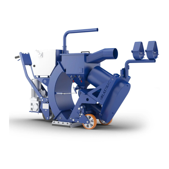
- Page 20 1-15DS Operating Instructions General 3.3 Description Fig. 3.1 Control box Blast wheel motor Separator Blast head, magnets, brush sealing Filter connection Dead man’s handle Rebound plenum Feed spout Drive mechanism 10 Abrasive control lever Like many revolutionary inventions the blast wheel method is based on a simple principle: after mechanical pre-acceleration the abrasive is thrown onto the surface at high speed by the blast wheel.
- Page 21 Operating Instructions 1-15DS General 3.4 Operating elements The control box is equipped with all control elements and instruments for monitoring and controlling the blast cleaning machine. Fig. 3.2 Control lamp “Control“ Push button “Control ON“ Push button “Control OFF“ Control lamp motor protection Control lamp “Blast wheel“...
- Page 22 1-15DS Operating Instructions General Push buttons ”Control ON/OFF”, Control lamp Pressing the push button "Control ON" switches the control on and makes the control lamp light up. Pressing the push button "Control OFF" switches the control off. Control lamp motor protection This red control lamp lights up when the complete electronics has been switched off by overload of one of the motors.
- Page 23 Operating Instructions 1-15DS General Drive speed control Although this indication does not allow direct reading of the actual speed, it shows comparing numbers allowing the operator to set the appropriate speed. Selection switch forward/backward This switch controls the direction of the drive motor.
- Page 24 1-15DS Operating Instructions General The abrasive valve Between the abrasive storage hopper and the feed spout there is a valve incorporating a permanent magnet in order to control the abrasive flow towards the blast wheel. Any change in the opening of the magnetic valve causes the amount of abrasive fed to the blast wheel to change.
- Page 25 Operating Instructions 1-15DS General Abrasive control lever This lever is located on the control box and regulates the magnetic valve to control the flow of abrasive towards the blast wheel. The valve is hand-operated and can be set to each amount of abrasive throughput by changing the lever position.
- Page 26 1-15DS Operating Instructions General 3.5 Blast wheel The heart of the blast cleaning machine is the blast wheel which throws the abrasive onto the surface to be cleaned by using centrifugal force. The blast wheel is placed in a protective housing lined with replaceable wear plates.
- Page 27 Operating Instructions 1-15DS General 3.6 Separator The abrasive separator is mounted to the end of the rebound plenum. It separates the abrasive from contaminants and feeds the cleaned abrasive back to the abrasive circuit. A wire mesh is fitted to prevent any coarse contaminants from getting into the blast wheel.
-
Page 28: Drive Mechanism
General 3.7 Drive mechanism The machine 1-15DS is driven by a 1,1 kW electric drive motor. The power is transmitted via a chain drive. The drive wheel and the chain disk are not linked rigidly. They are only linked after insertion of the quick release pin. - Page 29 Operating Instructions 1-15DS General 3.8 Abrasive sealing Magnetic seals are fitted to the front and the sides of the blast housing outlet and are surrounded by brush seals. At the rear there is a seal sliding over the floor. The seals are employed to seal the blasting area in a way to avoid leakage of any abrasive.
-
Page 30: Abrasive Media
Blastrac abrasive. The Blastrac abrasive is of very high quality and owns the rebouncing ability required for the efficient use of model 1-15DS. The selection of the abrasive is very important since this is the material to carry out the surface treatment. - Page 31 Operating Instructions 1-15DS General Media No. 3: Applications: creates a fine to medium texture on concrete removes glazing from tiles prior to subsequently coating with antiskid floor sealings removes old impregnations and coatings about 1 mm thick Media No. 4: Standard abrasive, suitable for about 50-60 % of all applications.
- Page 32 The effectiveness of the 1-15DS depends on the rebound effect which ensures that the abrasive can be re-used. Please take into account that the use of incorrect abrasive increases wear.
- Page 33 Operating Instructions 1-15DS General 3.10 Care and maintenance Special attendance and regular maintenance of the machine and its parts are imperative for functioning and safety. In order to prevent unnecessary downtimes it is recommended to keep original spare and wear parts on stock as listed in the maintenance box.
- Page 34 1-15DS Operating Instructions Transport Contents Chapter 4 4.1 General notes 4.2 Transport 4.3 Transport of the machine with vehicles 4.4 Operation conditions 4.5 Operation 4.6 Unit specifications...
- Page 35 1-15DS Transport 4.1 General notes Before the machine is used for the first time, Blastrac authorised dealers offer a course to familiarise maintenance and operating personnel with all elements of the machine. We are not liable for damage caused by incorrect use of the machine by personnel not trained by Blastrac.
- Page 36 The weight and dimensions of the machine are shown in Chapter 1 "Technical data“. The machine is to be transported after being separated into: Machine (1-15DS) Filter unit General accessories...
- Page 37 Operating Instructions 1-15DS Transport 4.3 Transport of the machine with vehicles When transporting the machine proceed in such a manner that damage due to the effects of the use of force or incorrect loading and unloading is avoided. Tighten the machine to the vehicle with straps.
-
Page 38: Initial Operation
1-15DS Operating Instructions Initial operation Contents Chapter 5 5.1 Preparations for initial operation 5.2 Initial operation... - Page 39 Operating Instructions 1-15DS Initial operation 5.1 Preparations for initial operation Before switching on make sure that all existing protective housings are mounted and that the filter unit is connected correctly. All persons in the proximity of the machine must wear safety glasses with lateral protection as well as safety shoes.
- Page 40 1-15DS Operating Instructions Initial operation Lubricate the wheel bearings of the drive wheel every 100 working hours. Make sure the dust container of the filter unit is empty. Please comply with the local waste treatment regulations considering the removed material.
- Page 41 Operating Instructions 1-15DS Initial operation Fig. 5.1 For the height adjustment, an 8 mm sheet steel strip is shifted below the magnetic sealing. Check the main power cable and the dust hose for damage. Replace or repair all damaged parts before starting the machine.
- Page 42 1-15DS Operating Instructions Initial operation Fig. 5.2 Check that the filter dust container has been emptied. Please comply with the local waste treatment regulations considering the removed material. 5.2 Initial operation All persons in the proximity of the machine must wear safety glasses with lateral protection as well as safety shoes.
- Page 43 Operating Instructions 1-15DS Initial operation Initial operation of the blast cleaning machine Check that the magnetic valves are closed (black lever in position “CLOSED“ Fig. 5.2). Press the push button "Control ON". Inserting the quick release pin Open the cover at the chain guard of the travel drive.
- Page 44 Find out the cause of the disturbance and, if necessary, contact your Blastrac customer service engineer. Set the travel direction switch to "backward" (working direction (3)). Select the speed using the drive speed control knob.
- Page 45 Operating Instructions 1-15DS Initial operation When blast cleaning concrete the abrasive magnetic valve may only be opened when the blast cleaning machine is travelling! If the machine is at a standstill and the valve is open deep holes may be blasted into the concrete surface within seconds.
-
Page 46: Operation
1-15DS Operating Instructions Operation Contents Chapter 6 6.1 Operation 6.2 Information about advancing speed 6.3 Recommended blast paths 6.4 Switching-off the machine 6.5 What to do if a fault occurs 6.6 Safety shutdown 6.7 Restarting after a fault 6.8 Measures before and after long standstills... - Page 47 1-15DS Operation 6.1 Operation Normal start-up and operation of the blast machine 1-15DS is no different from the procedure described in Chapter 5 "Initial operation". Carry out blasting in parallel tracks in such a way that the dust hose and electric cable do not become twisted.
- Page 48 1-15DS Operating Instructions Operation 6.3 Recommended blast paths Position the filter unit near to a power supply connection. Place the blast cleaning machine near to the filter unit and spread out the hose as shown in fig. 6.1. Work with the blast cleaning machine, with the hose spread out in the opposite direction, repeating the process away from the filter unit.
- Page 49 Make sure that all turning machine parts have come to standstill before any inspection or maintenance works are started. When the Blastrac blast cleaning machine is put out of operation for a longer period of time, pull out the mains plug and cover the machine with a plastic foil.
- Page 50 1-15DS Operating Instructions Operation 6.6 Safety shutdown The machine must be put to its safety off position before starting repair works. See Chapter 2 “Safety instructions”. 6.7 Restarting after a fault See Chapter 5 “Initial operation“. All persons in the proximity of the machine must wear safety glasses with lateral protection as well as safety shoes.
-
Page 51: Maintenance
1-15DS Operating Instructions Maintenance Contents Chapter 7 7.1 Recommendations 7.2 Maintenance and inspection list 7.3 Repairing 7.4 The blast pattern 7.5 Setting the blast pattern and the control cage 7.6 Setting the magnetic and brush seals 7.7 V-belts 7.8 Fitting the V-belts 7.9 Tensioning the V-belts... - Page 52 Operating Instructions 1-15DS Maintenance Contents Chapter 7 7.14 Maintaining and repairing the chain 7.15 Adjusting the chain tension of the travel drive motor 7.16 Wear parts 7.17 Changing the tune-up kit 7.18 Changing the liners...
- Page 53 1-15DS Operating Instructions Maintenance 7.1 Recommendations Prior to any repair works on the machine and its drives, secure the machine against unintentional switching-on. Put the machine to its safety off position. Failures due to inadequate or incorrect maintenance may generate very high repair costs and long standstill periods of the machine.
- Page 54 Operating Instructions 1-15DS Maintenance 7.2 Maintenance and inspection list Operating hours/ Inspection points, maintenance time period instructions 12 h after repairing Check the efficiency of all safety devices. Check all accessible screw connections for tight seat. every 3 h Check whether there is any foreign matter in the hopper, the feed spout or in the blast wheel unit.
- Page 55 As already mentioned in Chapter 5 “Initial operation” we recommend to execute the first repair works on the machine with the help of Blastrac personnel. With this your maintenance personnel gets the opportunity to be trained intensely. Only those repair works are described which occur within the context of maintenance or which are required to replace wear parts.
- Page 56 Operating Instructions 1-15DS Maintenance Every time the control cage is replaced, the thread of the blast wheel fastening screw should be checked. Make sure that this screw will be tightened correctly. In addition, absolute care must be taken to clean the thread from dust and abrasive.
- Page 57 1-15DS Operating Instructions Maintenance Worn tune-up kit: With increased wear of the tune-up kit (impeller, control cage) the blast pattern will change. Size of abrasive: The size of the abrasive affects the blast pattern. With every exchange of abrasive, the blast pattern must be re-adjusted.
- Page 58 Operating Instructions 1-15DS Maintenance The adjustment can be carried out as follows: Determine the upper (1) and lower (2) window edges. Set the upper window edge (1) of the control cage to imaginary 11.30 of a dial (see fig. 7.1). Place the cage clamps (3) and fix them with nuts (4).
- Page 59 1-15DS Operating Instructions Maintenance Fig. 7.2 Adjust the control cage until the hot spot (1) is exactly in the middle of the blast pattern. Now the blasting procedure can be started. When a concrete surface is to be blasted, check the blast pattern again after some meters and re-adjust slightly if necessary.
- Page 60 Adjust the height with the setting screws until the correct distance of 8- 10 mm has been reached. With the Blastrac model 1-15DS the adjustment is done using 4 setting screws (one each at the rear wheels and two at the front drive wheel bracket below the control box).
- Page 61 1-15DS Operating Instructions Maintenance 7.7 V-belts The V-belt drive is designed for the required drive power. Forcing the drive to grant a higher output by overtensioning the V-belt results in belt breaks, bearing damage and thus to lower efficiency. A low V-belt tension results in slippage causing an increased belt temperature and thus to premature destruction of the V-belts.
- Page 62 Operating Instructions 1-15DS Maintenance Tension the V-belt by increasing the distance between the shafts of the blast wheel motor and the blast wheel bearing unit as described below. Mount the pertaining protective drive equipment. 7.9 Tensioning the V-belts The correct V-belt pre-tension is of great importance for the perfect output transmission and for maintaining the normal service life of the V-belts.
- Page 63 1-15DS Operating Instructions Maintenance Threaded pins or screws are screwed to the stop in the boreholes using an Allan key. When the screws are tightened further using a certain amount of force the hub is drawn up to the tapered bush which is pressed onto the shaft with great force.
- Page 64 Operating Instructions 1-15DS Maintenance Knock the frontal face of the bush lightly with a hammer to make sure that the bush is seated in the centre of the pulley (use an aluminium or brass mandrel to avoid any damages). Now tighten the screws. Repeat the alternating hammering and tightening until all screws have been fully tightened.
- Page 65 1-15DS Operating Instructions Maintenance 7.13 Fitting the chain Before mounting the chain it must be degreased to prevent any abrasive or abrasive particles from adhering. The chain is supplied as a chain string and has to be prepared during mounting. This is done as follows: Place the chain on the chain wheels so that the links lie in tow adjacent gaps between the teeth.
- Page 66 Operating Instructions 1-15DS Maintenance In order to clean thoroughly first remove the dirt adhering to the outside of the chain drive using a hard or wire brush. Then wash the chain in petroleum ether or similar. After that clean the dirt from the internal parts of the chain.
- Page 67 1-15DS Operating Instructions Maintenance 7.16 Wear parts The tune-up kit Blast wheel Bolt and spring lock washer Control cage Fig. 7.10 The liners Left liner Top liner Right liner Plenum top liner Plenum side liner Plenum bottom liner Fig. 7.11...
- Page 68 Operating Instructions 1-15DS Maintenance 7.17 Changing the tune-up kit The tune-up kit consists of the blast wheel, control cage and fixing screw with spring lock washer. Demounting: Fig. 7.12 Remove the feed spout (1) by loosening the star nuts and pulling the feed spout out of the housing.
- Page 69 1-15DS Operating Instructions Maintenance Mounting: Fig. 7.13 Clean all threads and use a new blast wheel fixing screw. Place the blast wheel (2) on the wheel hub (1) through the blast housing opening. Tighten the blast wheel by fastening the fixing screw (3).
- Page 70 Operating Instructions 1-15DS Maintenance 7.18 Changing the liners Demounting: Loosen the pressure screws (1) of the top liner. Unscrew the screws (2) of the blast housing cover (3) and remove it. Loosen the fastening screws (4) for the left and right liners (5), turn the liners towards the inside of the blast housing and take them out at the bottom of the housing.
- Page 71 1-15DS Operating Instructions Maintenance Mounting: Prior to mounting the liners, check all threads for contaminants and clean them if necessary. First place the plenum liners (1) inside the housing and fix them with nuts. Place the side liners (2) inside the housing in a way that the bolt of the liner aligns with the hole in the housing.
-
Page 72: Electrical Systems
1-15DS Operating Instructions Electrical systems Contents Chapter 8 8.1 Recommendations for the electrical systems 8.2 Circuit diagrams 1-15DS... - Page 73 Order electric components referring to the circuit diagrams in Chapter 8.1 or contact Blastrac Customer Service. Observe regulations EN60204-1 VDE0701 (measurements after maintenance and repairs).
- Page 74 Particulars: PROJECT This draw. is issued solely for use with the following reference number 25589/1 Client Blastrac B.V. Use only in conjunction with this Name C.D. FOR 1-15 DS contract or order For external cable lenghts refer to Supplier Blastrac B.V.
- Page 75 Wiring dates 25.02.2005 Mountingplate 25.02.2005 Main-Voltage 25.02.2005 Main-Voltage 25.02.2005 Control-Voltage 25.02.2005 Main-Voltage 25.02.2005 Revision DRG. No. A3/C20573/L1 Start 25.02.2005 Arch.nr. Blastrac B.V. Contents PJ05.02575T1A Revision Eng. C.D. FOR 1-15 DS Draw.nr. Pages Page Revision Print 25.02.2005 PJ05-02575 Revision Status As Build...
- Page 76 -Yellow / Green Control-Voltage alternating current: Phase (VAC-A) -Red Hook-up wire -Red Zero (VAC-B) -Red Revision DRG. No. A3/C20573/L1 Start 25.02.2005 Arch.nr. Blastrac B.V. Wiring dates PJ05.02575T1A Revision Eng. C.D. FOR 1-15 DS Draw.nr. Pages Page Revision Print 25.02.2005 PJ05-02575...
- Page 77 Right-sideview Left-sideview Gt. 25 Gt. 25 Gt. 25 Gt. 25 Revision DRG. No. A3/C20573/L1 Start 25.02.2005 Arch.nr. Blastrac B.V. Mountingplate PJ05.02575T1A Revision Eng. C.D. FOR 1-15 DS Draw.nr. Pages Page Revision Print 25.02.2005 PJ05-02575 Revision Status As Build...
- Page 78 ¤ ¤ ¤ ¤ Supply Wheel Voeding Drive motor motor 230 VAC Revision DRG. No. A3/C20573/L1 Start 25.02.2005 Arch.nr. Blastrac B.V. Main-Voltage PJ05.02575T1A Revision Eng. C.D. FOR 1-15 DS Draw.nr. Pages Page Revision Print 25.02.2005 PJ05-02575 Revision Status As Build...
- Page 79 ¤ ¤ ¤ ¤ travel +t deg Drive motor Brake switch Revision DRG. No. A3/C20573/L1 Start 25.02.2005 Arch.nr. Blastrac B.V. Main-Voltage PJ05.02575T1A Revision Eng. C.D. FOR 1-15 DS Draw.nr. Pages Page Revision Print 25.02.2005 PJ05-02575 Revision Status As Build...
- Page 80 6 5.4 6 5.3 14 7.4 14 7.5 22 7.6 22 7.5 24 7.2 34 7.1 Revision DRG. No. A3/C20573/L1 Start 25.02.2005 Arch.nr. Blastrac B.V. Control-Voltage PJ05.02575T1A Revision Eng. C.D. FOR 1-15 DS Draw.nr. Pages Page Revision Print 25.02.2005 PJ05-02575...
- Page 81 Internal connection Bridges Terminal ¤ ¤ ¤ ¤ ¤ Revision DRG. No. A3/C20573/L1 Start 25.02.2005 Arch.nr. Blastrac B.V. Main-Voltage PJ05.02575T1A Revision Eng. C.D. FOR 1-15 DS Draw.nr. Pages Page Revision Print 25.02.2005 PJ05-02575 Revision Status As Build...
-
Page 82: Fault Diagnosis
1-15DS Operating Instructions Fault diagnosis Contents Chapter 9 9.1 Fault diagnosis - blast machine 9.2 Fault diagnosis - electrical system... - Page 83 Operating Instructions 1-15DS Fault diagnosis 9.1 Fault diagnosis - blast machine Prior to any repair works on the machine or its drives the machine must be secured against unintentional switching-on. Put the machine to its Safety off position. Fault Possible cause...
- Page 84 1-15DS Operating Instructions Fault diagnosis Fault Possible cause Remedy Reduced or "Shocked blast wheel". Close the magnetic valve no blasting At the start of the blast and stop the blast wheel performance process too much motor. Start the blast abrasive at once hits the process again and slowly wheel.
- Page 85 Operating Instructions 1-15DS Fault diagnosis 9.2 Fault diagnosis - electrical system Prior to any repair works on the machine or its drives the machine must be secured against unintentional switching-on. Put the machine to its Safety off position. Fault Possible cause...
- Page 86 1-15DS Operating Instructions Spare Parts Contents Chapter 10 10.1 Spare parts 1-15DS...
-
Page 87: Spare Parts
Operating Instructions 1-15DS Spare Parts 10.1 Spare parts 1-15DS Fig. 10.1... - Page 88 1-15DS Operating Instructions Spare Parts Item Part no. Description Qty. 453290 Handle grip 490074 Switch lever 454796 Limit switch B20415 Steering lever 973710 Oilite bush 971769 Bracket pin long B20514 Bearing shaft B20517 Bearing 971860 Washer for yoke shaft B20416...
- Page 89 Operating Instructions 1-15DS Spare Parts Fig. 10.2 Item Part no. Description Qty. 979965 Rebound plenum 1-15D(S) MK3 456550 Shock absorber B20515 Shaft cover 971341 Oilite bush B20511 Lifting plate B20295 Felt seal lifting plate B20512 Felt seal retainer...
- Page 90 1-15DS Operating Instructions Spare Parts Fig. 10.5 Item Part no. Description Qty. B20394 Left liner B20395 Right liner B20907 Top liner 970153 Plenum side liner 970151 Plenum top liner 970152 Plenum bottom liner...
- Page 91 Operating Instructions 1-15DS Spare Parts Fig. 10.3...
- Page 92 1-15DS Operating Instructions Spare Parts Item Part no. Description Qty. B20393 Separator 1-15DS B20263 Separator cover B20262 Deflector B20264 Separator tray B21325 Ball head for separator 001084 Clamp for separator tray B20446 Valve lever B20444 Magnetic valve assembly B20443 Feed spout...
- Page 93 Operating Instructions 1-15DS Spare Parts Fig. 10.4...
- Page 94 1-15DS Operating Instructions Spare Parts Item Part no. Description Qty. B20024-1 Blasthousing 1-15D(S) - idler B20454 Blast housing cover seal B20458 Blast housing cover B21920 Pin short B21915 Top lever B21916 Bottom lever B20842 Idler wheel B21921 Pin long B21918...
- Page 95 Operating Instructions 1-15DS Spare Parts Fig. 10.6...
- Page 96 1-15DS Operating Instructions Spare Parts Item Part no. Description Qty. B20277 Blast wheel motor B20224 Belt guard B20429/1 Top pulley (50Hz) B20431 Taperlock bush B20429 Top pulley with taperlock B20430/1 Bottom pulley (50Hz) 222-2172-V Taperlock bush B20428 Belt B20422 Motor bracket...
- Page 97 Operating Instructions 1-15DS Spare Parts Fig. 10.7...
- Page 98 1-15DS Operating Instructions Spare Parts Item Part no. Description Qty. B20536K Tune-up kit 969803 Control cage clamp 972781 Control cage shim 979644 Blast wheel cover plate B20397 Wheel hub B21629 Bearing unit B21624 Bearing unit flange B20295 Felt seal B21625...
- Page 99 Operating Instructions 1-15DS Spare Parts Fig. 10.8 Item Part no. Description Qty. B20519 Abrasive control lever B20520 Abrasive control cable B20521 Pivot for abrasive control cable...
- Page 100 Button for potentiometer 001222 Main cable B20439 Plug CEE 63 A 001281 Selection switch forward/backward B21086 Rubber seal for control box Contents Maintenance box 1-15DS Item Part no. Description Qty. 001071 Metal box 1-15DS B20536K Tune-up kit B20394 Left liner...
- Page 101 Operating Instructions 1-15DS Spare Parts Item Part no. Description Qty. 682652 Skid seal 001017 Open-end spanner 10 x 11 001018 Open-end spanner 13 x 15 001019 Open-end spanner 17 x 19 001042 Open-end spanner 24 x 26 001036 Ring spanner 8 x 9 000114 Ratchet spanner ½"...
Need help?
Do you have a question about the 1-15DS and is the answer not in the manual?
Questions and answers