Table of Contents
Advertisement
Advertisement
Table of Contents

Related Manuals for Blastrac 1-16DB4-V2


Summary of Contents for Blastrac 1-16DB4-V2
- Page 1 SERVICE MANUAL 1-16 DB4-V2 VERSION 1.1 www.blastrac.com 1-800-256-3440...
-
Page 2: Table Of Contents
Contents Introduction ..........................3 Safety ............................3 Advice for Operators of Blast Cleaning Machines ..............3 Warnings and Symbols ..................... 3 Organizational Measures ....................4 Fundamental Duties ......................5 General Safety Precautions ....................6 Definition of the Safety Off Position ..................8 General ............................ -
Page 3: Introduction
During operation the acceptable noise level of the 1-16DB4-V2 could exceed 85dB (A). This noise level depends on the job site. When the noise level is 85 dB (A) or more, the machine operator and persons working near the machine must wear sound-insulating equipment. -
Page 4: Organizational Measures
Indicates where consultation with the manufacturer is required. Instructions relating to periodic checks. Reference to important instructions contained in the operating instructions. Organizational Measures These operating instructions are to be kept with the machine, and must be within reach at all times! In addition to these operating instructions, general and legal regulations regarding accident prevention and environmental protection must be compiled with per local regulations. -
Page 5: Fundamental Duties
Spare parts must comply with the technical requirements specified by the manufacturer. This is always guaranteed if Blastrac OEM parts are used. Intervals for recurring checks and inspections specifies in these operating instructions must be followed. -
Page 6: General Safety Precautions
General Safety Precautions Do not allow any method of working that impairs safety. Recognized official procedures have to be used to ensure the machine is operated in the safest and best conditions. Only operate the machine when all safety devices, and related safety equipment, are present and operational. - Page 7 Mechanical servicing work: Put the machine in the Safety Off Position as described on page 8 before carrying out any service work on the machine. Follow any special safety instructions in sections on servicing the machine. See Section 5. Service and maintenance intervals specified in these Operating Instructions, as well as information on the replacement of parts must be followed.
-
Page 8: Definition Of The Safety Off Position
Definition of the Safety Off Position Definition: The machine is in a safe condition where it cannot be a hazard. Putting the equipment in the Safety Off Position involves: Close the shot valve. Switch off the machine. Wait for all drives to stop. ... -
Page 9: General
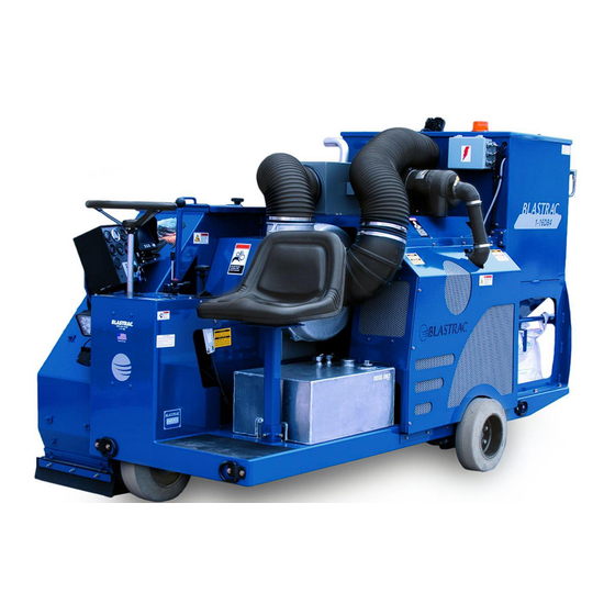
Description of the Machine The 1-16DB4-V2 Shot-Blast machine is powered by a 61 HP Duetz Diesel engine. The machine is capable of removing up to 1/4 inch of concrete in one pass. It is driven by a hydrostatic pump and motor system. -
Page 10: Transportation
16 in General Transport of the Machine Before the machine is used for the first time, Blastrac authorized dealers offer a course to familiarize maintenance and operating personnel with all elements of the machine. Blastrac is not liable for damage caused by incorrect use of the equipment by personnel that have not trained by Blastrac. -
Page 11: Tie-Down Locations
Tie-Down Locations There are 4 tie-down locations, as show below. Front Tie-Downs Side Tie-Downs... -
Page 12: Operation
Operation Preparation for Operation Check the surface to be treated for loose parts (stones, screws, etc.). The surface must be swept, if necessary. Make sure that the machine can travel over all inequalities on the surface. Small inequalities like weld seams or floor joints are no barriers for the machine. -
Page 13: Operator Awareness
Operator Awareness The 1-16DB4-V2 machine is designed to blast a concrete surface and reclaim all shot and dust. The machine can very easily destroy the concrete surface if not operated properly! The absence of operator awareness will create down time and can prove to be very costly. -
Page 14: Engine Startup
• The gap between the blades and the pinch bar is very important. If your gap exceeds 3/16 inch, you will begin to trail shot and eventually empty the shot hopper. • The shot blast machine is equipped with blast seals. These seals provide a seal for the suction required. - Page 15 GAUGES: VOLTS- shows the voltage being supplied from the charging system. FUEL LEVEL- show the amount of diesel in the fuel tank. ENGINE RPM- shows the current revolution per minute of the engine. OIL PRESSURE- shows engine oil pressure in pounds per square inch.
- Page 16 Before starting the engine, make sure the clutch is in the disengaged position. Failure to do so will result in damage to the clutch. “Cold” Startup Procedure: Turn the ignition switch to the run position and wait for the glow plug light to turn off.
-
Page 17: Operation Adjustments
Operation Adjustments The 1-16DB4-V2 is equipped with a few fine tune adjustments to make blasting easier. Front End Lift: This is used primarily for loading and unloading the machine. This feature may also be used to adjust your seals while operating the machine, opposed to stopping the machine and doing it manually. -
Page 18: Operation Sequence
Operation Sequence Throttle Shot Valve Control Open / Close Transmission Control Blast Head Raise / Lower Figure 3 Refer to Figure 3 for the location of switches and controls identified in this procedure. Complete the Operation/Maintenance Checklist (pages 12-13). Place the transmission control lever in the neutral (center) position. Follow the startup procedures in on page 16, as appropriate. - Page 19 Only operate this machine when sitting in the operator seat. DO NOT OPERATE THIS MACHINE WHEN STANDING IN FRONT OF IT! Figure 4...
-
Page 20: Dust Collector Function
Dust Collector Function This unit is equipped with an auto pulse dust collector that provides suction to separate the dust from the shot. Refer to Figure 5 for the location or items discussed in this section. The central part of the dust collector is the filter chamber. Dust laden air enters the chamber from the blast head through the exhaust hose and into the dust collector inlet connection located on the center, front side of the dust collector. -
Page 21: Dust Collector Parts
Dust Collector Parts Pulse Valve Tank Blow Down Tube Dust Collector Outlet Venturi Filter Cartridge Dust Collector Inlet Dust Bag Figure 5... -
Page 22: Shutdown Sequence
Shutdown Sequence Ensure the shot valve is fully closed. Push the throttle to the closed position. Ensure the clutch is in the off position. Ensure the transmission lever is in neutral position. Turn the key to the off position. Complete the maintenance check list. Safety Shutdown The machine has to be in its Safety off position before starting repair work. -
Page 23: Maintenance
Maintenance Blade Replacement The key must be in the off position and all rotating parts must come to a complete halt before attempting any maintenance procedure. Ensure you are in the Safety Off Position, on page 8. Figure 6 ITEM NO. PART NUMBER DESCRIPTION QTY. - Page 24 Remove Item #1, Pinch Bar Outside Liner. Remove Item #2, Pinch Bar Inspection Plate. Rotate the blast wheel to bring Item #3, Blast Wheel Blade, that is to be removed into reach. Remove Item #4, Bolt and Blade keeper, at the end of the blade. Blow dust and shot out of the threaded hole in the end of the blade.
-
Page 25: Pinch Bar Removal, Installation, And Re-Positioning
Pinch Bar Removal, Installation, and Re-Positioning Figure 7 ITEM NO. PART NUMBER DESCRIPTION QTY. 08300093 RETAINER/ PINCH BAR 08300042 INDEXER/PINCH BAR 3 & 4 P002712 RETAINER/OUTER PINCH BAR WP033711 PINCH BAR... - Page 26 The key must be in the off position and all rotating parts must come to a complete halt before attempting any maintenance procedure. Ensure you are in the Safety Off Position, as described in page 8. Pinch Bar Re-positioning: MUST BE DONE EVERY 10 HOURS OF OPERATION. (See Figure 7 for item descriptions and locations) 1.
-
Page 27: Blast Wheel Removal And Installation
Blast Wheel Removal and Installation Figure 8 ITEM NO. PART NUMBER DESCRIPTION QTY. 2110015 3-BOLT FLANGE BEARING WP143706 ACCESS-PLATE/BLAST HOUSING P000830 COVER-PLATE/BLAST HOUSING WP093716 LINER/SIDE - REAR OUTSIDE LOWER SLL WP053708 LINER/SIDE - REAR UPPER OUTSIDE SLL WP053704 LINER/SIDE - FRONT INSIDE/OUTSIDE UPPER SLL WP093707 LINER/SIDE - FRONT OUTSIDE LOWER SLL 8300171... - Page 28 Bearing Collar: Remove the two hex head set screws on each of the two bearing collars. Outside Blast Wheel Bearing: Remove the three nuts holding the bearing, Item #4. b. Pry the bearing off of the shaft. Access Plate: Remove the two nuts which connect the access plate, Item #5, to the housing. b.
-
Page 29: Liner Removal And Stack Up
Liner Removal and Stack up Figure 9 ITEM NO. PART NUMBER DESCRIPTION QTY. WP113715 Liner/Top Curved SLL WP053704 Liner/Side - Front Inside/Outside Upper SLL WP053712 Liner/Side - Rear Inside Upper SLL WP093706 Liner/Side - Lower Inside SLL 02110015 Bearing/FLG3 1.4375" B 3-Bolt P002823 Outside Bolt Retainer/ 3 Bolt Flange Bearing... - Page 30 Top Liner Removal: See Figure 9 for item locations and descriptions. Before attempting to remove the Top Liner, steps 1-8 of Blast Wheel Removal must be completed. If the Top Liner has completed more than 100 hours of blasting it will have expanded. In the event that the Top Liner has expanded too much to slide out, the best way to remove it is to cut it in half with a torch.
- Page 31 Figure 10 ITEM NO. PART NUMBER DESCRIPTION QTY. WP033711 Pinch Bar WP043709 Liner/Upper Front SLL WP043715 Liner/Front Lower SLL WP103712 Liner/Back Wall SLL WP113715 Liner/Top Curved SLL WP053704 Liner/Side - Front Inside/Outside Upper SLL WP053712 Liner/Side - Rear Inside Upper SLL WP093706 Liner/Side - Lower Inside SLL WP093716...
-
Page 32: Dust Collector Maintenance
Filter Cartridge Removal Prior to attempting to change or inspect the filter cartridges, place the 1-16DB4-V2 on a level surface to prevent movement. Verify that the machine is in the Safety Off Position. Access to the filter cartridges is gained through the door on the rear of the dust collector. -
Page 33: Engine Maintenance
INNOVATORS IN SURFACE PREPARATION .BLASTRAC Engine Maintenance Care and maintenance work Lubricating system The oil level must always between the Regulations working lubricat system essary. Do not work when the engine running! Changing lubricating Smoking and naked lights prohibited! Be careful of lubricating oil. - Page 34 • until gasket is in place andthen tighten with torque of 15-17 • Fasten clamps twist protection (optional). • S...
- Page 35 INNOVATORS IN SURFACE PREPARATION .BLASTRAC Care and maintenance work Fuel system Specifications when working on the fuel system Clean the engine enginecom- l.:_g partment thoroughly before beginning Engine must be switched off! work. Smoking and naked lights prohibited! Areas of...
- Page 36 • Check for leaks after starting the engine.
- Page 37 INNOVATORS IN SURFACE PREPARATION .BLASTRAC Care and maintenance work Fuel system • Change the fuel filter cartridge the gasket the new DEUTZ originalfilter cartridge lightly. • The filter cartridge should never be pre- Screw on new filter handuntil the gasket is filled.
- Page 39 INNOVATORS IN SURFACE PREPARATION .BLASTRAC Care and maintenance work Fuel system with fuel. bubbles. • • Assembly in clockwise direction. Catch escaping fuel. • • Open fuel shutoff tap vent system, Tighten the venting screw (7). see venting fuel system.
- Page 41 INNOVATORS IN SURFACE PREPARATION .BLASTRAC Care and maintenance work Engine cleaning Cleaning work Cleaning with cold cleaner • Spray the engine with cold cleaner and leave work, cleaning make sure that L..f£J about 10 minutes take effect. parts are damaged (e.g.
- Page 43 ,,.. INNOVATORS IN SURFACE PREPARATION .BLASTRAC Suction system Care and maintenance work Regulations for working on the intake system Renewing the safety cartridge of the dry air filter / I\ not work when the engine running! Never clean the safety cartridge (4).
- Page 45 INNOVATORS IN SURFACE PREPARATION OBLASTRAC Care and maintenance work Belt drives Checking the belt tension Tighten the generator V-belts • • Lower indicator arm into measuring Loosen screw(1), slightly. Only carry work belt drive with vice. • Push the generator outwards direction engine...
-
Page 47: Spare Parts
Clutch Maintenance Lubrication The PTO requires lubrication with NGLI #2 lithium based grease. During normal operation, apply one grease gun shot of grease to the release mechanism (sliding sleeve assembly) fitting every 20 hours of operation. Also lubricate the main bearings (located on the clutch shaft) and lever (operating) shaft every 100 hours of operation with one grease gun shot. - Page 48 Release locking pin after completing adjustment Replace inspection cover nameplate. Note: New friction discs require frequent adjustments during an initial break-in period. Please recheck clutch adjustment after the first 10 hours of operation. Clutch Adjustment Frequency As clutch wears, the hand lever force required to engage clutch will decrease. The need to readjust the clutch is indicated when the handle force has decreased to 2/3 of the maximum force specified on the inspection cover plate OR anytime clutch slippage is detected.
-
Page 49: Grease Points
Grease Points Apply two pumps of high temperature grease, every 8 hours. Follow the instructions, listed on page 40, for lubricating the clutch. Figure 11... - Page 50 IN SURFACE PREPARATION .BLASTRAC Figure 12...
- Page 51 • . . . ::!, Pos. Male AooesSOl"j' (15) 11}2 16 AWG l'l'rut• Tachometer <;, 16AWGGree Alc-em s tor Ga119 16 AWG Blue Pressure G:3.u9e 16 AWG """ - " s· 16 AWG Tan Preh.ea1Control tte<y+ (3 D) 14AWGPu..,_, Solencid .Ae.lx Switch 2 Ye ff...
- Page 52 er/SW i1ch...
- Page 53 • ---------------------------[ ' ; ; a = - " ' c = a lll sbner lnsllllle<I . ,. 1 H1 23-H1 Vokmeter 16AWGWhi'.e 12AWGRed J7-_H1 15-H 16AWGCJra 12 AWG Red/Black 16AWG Ute Blue atl'.omot, H lm 14-H kces""'f (25) P4-H2 J22-H1 Accessory (FU5ed)
- Page 54 IN SURFACE PREPARATION .BLASTRAC ..I i'.l □ "" -:;:- L'.l l.'.l L.:l > µ_ L... 1,/1 • • --j11 n, LI " _:,:_ _l,! " l'.l «I r--, ------7 • " -1-' r------- 'CJ_ ,I...' • "!l...
- Page 55 • ¥- • " r,· □ "f J:[l <'+...
- Page 56 Spare Parts Wear Parts CP-10727 - Bearing CP-10724 - Pulley CP-10748 - Pulley PA-11184 - Jack Shaft Figure 13 ITEM NO. PART NUMBER DESCRIPTION QTY. CP-10695 BELT/ 3VX710, 2 STRAND CP-10694 BELT/3VX560, 4 STRAND CP-10693 BELT/3VX750, 3 STRAND 2100002 BEARING/1" PILLOW BLOCK 2110004 BEARING/1 1/4"...
- Page 57 VATORS IN SURFACE PREPARATION .BLASTRAC Blast Head Assembly Figure 14...
- Page 58 ITEM NO. PART NUMBER DESCRIPTION QTY. P000829-1 BLAST HOUSING P000830 COVER PLATE WP143706 ACCESS COVER WP103711 LINER/PINCH BAR WP033711 PINCH BAR 8300190 DAMPER-PLATE/SEPERATOR WP043709 LINER/FRONT UPPER WP043715 LINER/PINCH BAR LOWER WP103712 LINER/PINCH BAR BACK WALL WP113715 LINER/PINCH BAR TOP 8300133 TRAY/SHOT WP053704 LINER/UPPER FRONT SIDE...
-
Page 59: Contact
7.Contact Blastrac NA 13201 North Santa Fe Avenue Oklahoma City, OK 73114 Tel: 800-256-3440 Fax: 405-478-8608 www.blastrac.com... - Page 60 13201 North Santa Fe Avenue Oklahoma City, OK 73114 Ph: 800-256-3440 F: 405-478-8608 blastrac.com Product Warranty Standard Equipment Products: Blastrac warrants its Blastrac Standard Equipment Products against defects in quality of material and workmanship, under normal and proper use for a period of 1 Year from the date of delivery, as noted on the returned warranty registration card, or, in the case of Rental Fleet Machines, 180 Days from the date of assignment to Rental Fleet.
- Page 61 8. The above warranty conditions can only be altered by Blastrac. Blastrac must confirm alterations in writing for each specific transaction. 9. Blastrac reserves the right to modify this warranty for used or demo products on an individual transaction basis. Blastrac will include warranty modifications on its invoices for used or demo products.
- Page 62 ® the information recorded here by registering online at blastrac.com, or complete this page and fax to 866-485-1046, or if you prefer, detach and mail to: Blastrac, 13201 North Santa Fe Avenue, Oklahoma City, OK 73114-9901...
Need help?
Do you have a question about the 1-16DB4-V2 and is the answer not in the manual?
Questions and answers