
Related Manuals for Irritrol Rain Dial-R


Summary of Contents for Irritrol Rain Dial-R
- Page 1 Irrigation System Controller User’s Guide • Setup • Installation • Programming • Troubleshooting v Indoor and Outdoor 6-, 9-, and 12-station Models v...
-
Page 2: Table Of Contents
Connecting an Earth Ground Device ........ 14 Connecting the Power Source ......... 15 Controller Station Test Feature ........17 Getting the Most From Your Rain Dial-R Controller ....18 What the Display Indicates ............20 Programming Mode ............20 Basic Programming Procedures ..........23 Setting the Current Time and Day ........ - Page 3 Special Functions ..............27 Rain Delay ..............27 Water Budget ..............27 Stack/Overlap ..............29 Station Delay ..............30 Pump Control During Station Delay ......... 30 Pump Control Option ..............31 Diagnostic Circuit Breaker ............31 Fuse Replacement ..............31 Manual Operations ..............32 Semi-Automatic Program Operation ......... 32 Manual Station Operation..........
-
Page 4: Getting To Know Your Rain Dial-R Controller
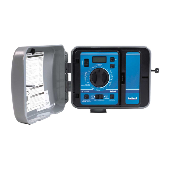
Getting to Know your Rain Dial-R Controller To take full advantage of your new Rain Dial-R controller, take a few moments to become familiar with its many features: • Modular design – Provides easy access to valve connection termi- nals and battery storage. Snap-out design enables the control mod- ule to be easily removed for “Armchair Programming.”... - Page 5 • MV/Pump control during station delay – Enables Master Valve/ Pump operation to be active or inactive during a station delay period. — Rain Dial-R provides the choice! • Built-in circuit protection – Helps protect the controller’s elec- tronic components from damage due to power and nearby lightning surges.
-
Page 6: Getting Started
Battery Installation & Armchair Programming Installing a 9V battery (user-provided) serves two important functions: first, it enables the Rain Dial-R to be fully programmed prior to installation, and second, it keeps the control module synchronized with current time and date during a main power interruption lasting up to 24 hours. - Page 7 Figure 1 Battery Compartment Cover 9-Volt Alkaline Battery (not included) EARTH GROUND...
-
Page 8: Overview: Control Module Interface
Overview: Control Module Interface 1 - Program Switch Three-position slide switch used to select Program A, B or C for setup, program review and manual operation. 2 - LCD Display High-contrast LCD panel displays all controller programming and operating information. 3 - Plus and Minus Buttons Push buttons used to increase and decrease display values during controller setup, programming and manual operations. - Page 9 Figure 2...
-
Page 10: Overview: Internal Controller Components
Valve connection terminals – one terminal for each valve. (Terminal layout varies by model – 12-station model shown.) 12 - Handheld Remote Control Plug-in Port Modular connector port required for the Irritrol handheld remote control system models R-100-KIT or for CLIMATE LOGIC weather sensing system. - Page 11 Figure 3 EARTH 24 VAC 10 11 12 GROUND Pump Sensor...
-
Page 12: Installation Procedures
Installation Procedures Installing the Controller Cabinet Select a sheltered location for the indoor model Rain Dial-R such as a garage or service room, preferably within 5' (1.5m) of a grounded electrical outlet. For outdoor controllers, choose a location that protects against direct exposure to sun and contact with irrigation spray, and is at least 5' (1.5m) away from any motorized equipment. - Page 13 operating sequence order. Connect the common wire to the terminal labeled “VC.” If applicable, connect one leg of the master valve or pump start relay control wire to the terminal labeled “MV/PUMP”, and the remaining leg to the valve common wire. Note: The controller does not supply power to operate a pump.
-
Page 14: Connecting A Rain Sensor (Optional)
Connecting a Rain Sensor (optional) The Rain Dial-R is designed to work in conjunction with Irritrol Rain Sensor models RS500, RS1000 or Rain/Freeze sensor RFS1000 to restrict watering when moisture and/or temperature limits are met. Note: If connecting an alternate make of rain sensor, ensure it provides normally-closed switch circuit operation. -
Page 15: Connecting A Remote Control Unit (Optional)
As shown in the illustration below, the R-100-KIT receiver assembly simply plugs into the receptacle provided in the back of the Rain Dial-R control module. Note: Irritrol’s CLIMATE LOGIC weather sensing system’s receiver module plugs in the same way. -
Page 16: Connecting An Earth Ground Device
Connecting an Earth Ground Device Note: In order for the electrical surge components built into your Rain Dial-R to function properly, the controller must be connected to an earth ground device, such as a copper-clad ground rod or metal water pipe, using solid copper wire. -
Page 17: Connecting The Power Source
Indoor models ship prewired with a power cord ready to be plugged into a standard wall power socket. Note: To immediately test-run the Rain Dial-R irrigation control system, refer to the “Controller Station Test Feature” on page 8. Figure 8... - Page 18 Connecting the Power Source - Outdoor Models Warning: All electrical components and connection methods Today must comply with all applicable national and local electrical codes including installation by qualified personnel. These codes may require a junction box installed on controller’s 1/2" (13mm) NPT nipple and a means in the fixed wiring of disconnecting AC power having a contact separation of at least 0.120"...
-
Page 19: Controller Station Test Feature
Apply power to the controller and check controller operation. If the controller is not operating, disconnect the power at the source and have a qualified electrician check for possible short circuit. Caution: For maximum Figure 10 protection of the controller electronic components when installed outdoors, always keep the cabinet cover closed... -
Page 20: Getting The Most From Your Rain Dial-R Controller
To accommodate this, the Rain Dial-R provides three independent watering Programs: Valve locations A, B and C. The example below shows how multiple Programs can be used to easily... - Page 21 Help with electrical problems The Rain Dial-R will display the station number and the word “FUS” if a short-circuit on a valve station is detected. The detected station will be bypassed, allowing the remaining operable stations to run in the Program...
-
Page 22: What The Display Indicates
What the Display Indicates The following examples represent the display information provided to assist you within the various programming, setup and operating modes. Programming Mode (Function – Set Programs) • Current Time - Displays the current time of day. • Valve Run Times - Displays the run time set for a selected valve number. - Page 23 • Well Recovery Time - Indicates the delay time (00–59 seconds, 1–59 minutes or 1– 2 hours) set to occur between stations in a watering cycle. • Pump Operation during Station Delay - Indicates pump operation is set to On or Off during a station delay period.
- Page 24 Run Mode (Function – Run) • Automatic Mode (Dial – Current Time) - Active valve number and current time are shown. (Dial – Active valve number)- active valve number, current Program and remaining run time. Note: If Water Budget is active, the adjusted run time will be shown.
-
Page 25: Basic Programming Procedures
Basic Programming Procedures Setting the Current Time and Day Place the Function switch in the Set Programs (center) position. Turn the Dial to the Current Time position. Press the button to set the current time (note AM/PM). Note: When using the button, press and release to adjust in steps, or press and hold to scroll. -
Page 26: Setting The Program Cycle Start Time(S)
Setting the Program Cycle Start Time(s) Each Program can have three separate start times. For mature landscapes, one start time per Program is generally sufficient. When establishing a new lawn, using two or three start times with short valve run times can provide the additional irrigation required for grow-in, at a reduced rate to help prevent runoff and erosion. - Page 27 Return the Function switch to the Run position. Note: Each Program can have a Skip Days or an Odd/Even Date watering schedule, but not both. One schedule must be turned off to enable the alternate schedule to be selected. To Set a Skip Day Schedule: Place the Function switch in the Set Programs position.
- Page 28 Press the buttons to adjust the month setting. JA - January Fe - February MR - March AP - April My - May, JN - June, JL - July AU - August SE - September, OC - October nO - November DE - December. Press the Manual button (one time) to select the Day setting.
-
Page 29: Special Functions
Special Functions Rain Delay The Rain Delay feature (for use when a weather sensor is not installed) enables automatic watering operation to be suspended for a period of 1 to 9 days; then resume watering automatically as scheduled. Place the Function switch in the Set Programs position. Turn the Dial to the Skip Days - Special Functions position. - Page 30 Budget adjustment value. Conversely, to apply a basic Water Budget, all months must be set at 100%. To Apply a Basic Water Budget: Turn the Dial to the Skip Days - Special Functions position. Select Program A, B or C. Place the Function switch in the Set Programs position.
-
Page 31: Stack/Overlap
For example, April 4 would be displayed as A:04. 10. Press the Manual button one time to select the Year setting. 11. Press the buttons to select the current year (09 = 2009). 12. Press the Manual button (as needed) to select the Monthly Water Budget display. -
Page 32: Station Delay
Station Delay Irrigation systems that utilize a well-water source or have slow- closing valves, may require a delay period to occur between consecutive stations during a watering cycle. The Station Delay feature enables a delay period to be set from 1 second to 2 hours. Place the Function switch in the Set Programs position. -
Page 33: Pump Control Option
Pump Control Option By default, the pump control circuit is activated simultaneously with any automatic or manual valve station operation. When pump operation is not required for specific valve stations; e.g., drip irrigation, the pump control circuit can be easily disabled as needed. Note: The Pump control option applies to the selected valve station regardless of its Program assignment. -
Page 34: Manual Operations
in the retaining clip. Reconnect power to the controller. Manual Operations Semi-Automatic Program Operation Semi-Automatic Program operation enables an automatic Program water- ing cycle to be started manually at any time. Once running, the manual advance feature enables you to step through the programmed station sequence. -
Page 35: Clear Program Memory
Program including: start times, run times, and watering day schedule. Note: To reset the controller (all Programs) to factory default settings, refer to “Restore Rain Dial-R to Factory Default Settings” on page 35. Place the Function switch in the Set Programs position. -
Page 36: Restore Factory Default Settings
Return the Dial to the Current Time position. Return the Function switch to the Run position. Restore Factory Default Settings The Rain Dial-R factory default settings for automatic program operation are as follows: Current Time: 12:00 AM. Current Day: Sunday. -
Page 37: Troubleshooting Guide
display. * The numerous button depressions required are to avoid inadvertent or accidental erasure. Troubleshooting Guide Problem Possible Cause Correction Display blank. No power. Check transformer/power connections, 2A fuse, and AC power. Some valves do not Faulty or improper valve Check and correct all valve operate. -
Page 38: Contact Information
Rain Dial-R controller. If the problem is not listed or cannot be resolved with the provided solutions, contact an authorized Irritrol product expert for assistance via phone or email. U.S./Canada: Phone: 1-800-634-8873 (7:30 am–4 pm, M–F, PT) E-mail: irrigationsupport@irritrol.com... -
Page 39: Fcc Rules
FCC Rules This equipment has been tested and found to comply with the limits for a Class B digital device, pursuant to Subpart J of Part 15 of the FCC Rules. These limits are designed to provide reasonable protection against harmful interference in a residential installation. - Page 40 Notes © 2019 Irritrol www.irritrol.com 373-0538 Rev. D...
Need help?
Do you have a question about the Rain Dial-R and is the answer not in the manual?
Questions and answers
What is setting for maximum water ?
The maximum Water Budget setting for the Irritrol Rain Dial-R is 200%.
This answer is automatically generated
What setting do I use for maximum water delivery?
Controller programmed correctly. Has power to controller. Sprinkler will not come on at set time/day when in run position.
The Irritrol Rain Dial-R controller may not be activating the sprinkler at the scheduled time and day despite being programmed correctly and having power due to the following reasons:
1. Battery Issue: The internal battery keeps the control module synchronized with the current time and date during power interruptions. If the battery is dead or disconnected, the time and date may be incorrect, affecting the scheduled operation.
2. Main AC Power Requirement: The battery is not capable of operating the sprinkler valves. If the controller has power but the main AC supply is insufficient or disconnected, the valves will not activate.
3. Non-Volatile Memory Check: While the controller retains programming even if the battery dies, verifying that the schedule remains intact after a power loss is essential.
4. Valve or Wiring Issues: The sprinkler valves may have wiring problems or a malfunction preventing activation, even if the controller is functioning correctly.
5. Fuse or Electrical Issue: The controller has a fuse and electrical components that may need inspection if the system is not functioning as expected.
Checking these potential issues should help diagnose and fix the problem.
This answer is automatically generated