
Related Manuals for Irritrol MC-4E


Summary of Contents for Irritrol MC-4E
- Page 1 MC -E (Blue) Installation Instructions and Programming Guide For Controller Models: MC-4E, MC-6E, MC-8E, MC-12E, MC-18E, MC-24E, MC-30E, MC-36E, MC-42E & MC-48E RELEASED Version ©Toro 2012-2012...
-
Page 2: Table Of Contents
Table of Contents Thank Introduction -- -- -- -- -- -- -- -- -- -- -- -- -- -- -- -- -- -- -- -- -- -- -- -- -- -- -- -Pg. 3 capab Parts Diagram -- -- -- -- -- -- -- -- -- -- -- -- -- -- -- -- -- -- -- -- -- -- -- -- -- -- -Pg. 3 MC-E Cabinet Installation - -- -- -- -- -- -- -- -- -- -- -- -- -- -- -- -- -- -- -- -- -- -- -- Pg. -
Page 3: Introduction
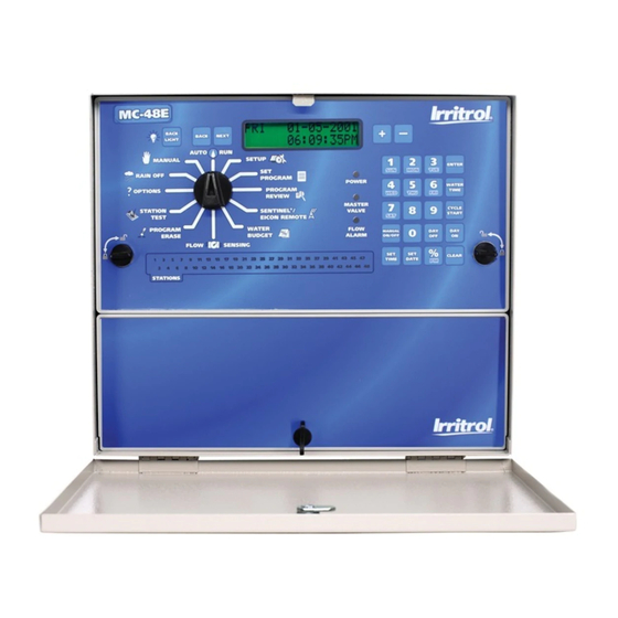
Introduction Thank you for purchasing the MC-E controller by Irritrol. The MC-E controller is a solid-state irrigation controller, capable of storing eight independent programs designed to meet the needs of commercial and contractor applications. The MC-E is an enhancement to the existing MC controller with many more functions and display features. The new MC-E is designed to be compatible with the previous MC Plus B cabinets and wiring connections. -
Page 4: Cabinet Installation
The MC-E series has two available lockable, weather and vandal resistant steel pedestals for free standing applications. For MC-E controllers with 12 stations or less, use the Irritrol P-2B pedestal. For MC-E controllers with 18 stations or more, use the Irritrol P-6B pedestal. Follow the installation and mounting instructions that are provided with the pedestal. -
Page 5: Control Wires Installation
Control Wires Installation Step 1 – Route the valve control wires between the valves and the MC-E controller. For wire runs up to 1000’ between the controller and the valves, it is recommended to use an 18 AWG (1.0 mm ) multi-wire sprinkler valve connection cable. -
Page 6: Rain Sensor Installation (Purchased Separately)
Rain Sensor Installation (Purchased Separately) 11 13 15 17 19 21 23 25 27 29 31 33 35 37 39 41 43 45 47 10 12 14 16 18 20 22 24 26 28 30 32 34 36 38 40 42 44 46 48 IMPORTANT! The INHIBIT SENSOR is designed for a normally closed rain sensor. -
Page 7: Power Source Installation
Power Source Installation WARNING: All electrical components and installation practices must meet applicable national and local electrical codes including installation by a qualified personnel. These codes may require an external junction box mounted on the cabinet and a circuit breaker in the main wiring having a contact separation of at least 0.120” in the line and neutral poles. 11 13 15 17 19 21 23 25 27 29 31 33 35 37 39 41 43 45 47 10 12 14 16 18 20 22 24 26 28 30 32 34 36 38 40 42 44 46 48 The 120 VAC power source must be turned OFF prior to servicing. -
Page 8: Power On / Reset Mode
Power On / Reset Mode Step MC-E will initiate the operating system and reload all saved data in the memory for stable operation every time the controller is powered up. Place the Function Dial in the Auto/Run position for normal operation. Initial Display Auto Run Mode Display Step... -
Page 9: Current Time
Step 4 – Press the button to accept the changes. The display will now reflect the new date. International format U.S. format While in SET DATE mode, you can advance to the SET TIME mode by pressing button. Step 5 – Return the Function dial to AUTO/RUN position to exit SETUP. -
Page 10: Security Password
SETUP – Security Password The MC-E can be secured with a security password to ensure that unauthorized users are not able to modify the programs. Set M Enable Security Password is acti Step 1 – Place the Function Dial to the SETUP position. -
Page 11: Set Master Valve On Or Off Per Station
SETUP – Master Valve ON or OFF per Station rams. Set Master Valve As factory default, the Master valve is Enabled for all stations. The master valve will activate whenever a station is activated. If flow sensing is to be activated, all stations must be set to “MV=ON”. In situations that a station does not require the master valve to activate, use the following procedure to select the station and Disable or Enable the master valve. -
Page 12: Program Setup
Program SETUP Ente Step For a watering program to operate properly, it must have a station(s) with a runtime and a specific date and time to activate. The following program parameters can be defined and/or modified in the SET PROGRAM function: •... - Page 13 Enter/Modify/Delete - Single or Multiple Stations Step 1 – Place the Function Dial to the SET PROGRAM position. Step 2 – Enter the program number (1–8) being modified. Press to activate the selection. button to clear any “Key Entry Error”. Press the Step 3 –...
-
Page 14: Program Start Time
Set Program – Program Start Time Dele Step Set Program Start Times Each MC-E program can have up to eight start times. Programs can start at anytime except midnight. Step Step 1 – Place the Function Dial to the SET PROGRAM position. - Page 15 Delete Program Start Time Step 1 – Place the Function Dial to the SET PROGRAM position. Step 2 – Enter the program number (1–8) being modified. Press the to activate the selection. button to clear any “Key Entry Error”. Press the Step 3 –...
-
Page 16: Station Delay Time
Set Program – Station Delay Time Station delay time is the adjustable delay period between station operations. The controller’s default station delay is 0 The M seconds. The maximum delay time you can set between station operation is 4 hours. delay To ini Assign Station Delay Time... -
Page 17: Looping Start Time
Set Program – Looping Start Time The MC-E has the capability to loop a program. When a program is set to loop, the program will repeat after the loop delay time is satisfied. The program will continue to repeat beginning from the start time until the designated end time. To initiate the program to loop, you must assign a start time, end time and a loop delay to the program. - Page 18 Modify a Looping Start Time Step 1 – Place the Function Dial to the SET PROGRAM position. The M optim Step 2 – Enter the program number (1–8) being modified. Press the to activate the selection. Each button to clear any “Key Entry Error”. Press the •...
-
Page 19: Watering Day Schedule
Set Program – Watering Day Schedule The MC-E offers you several options to schedule your watering programs. Having multiple options will allow you to optimize your watering need while practicing water conservation. Each of the eight controller programs can be set to one of the following schedule options: •... - Page 20 Odd Days watering schedule will activate the program on the odd-numbered days in the calendar month (1, 3, 5, ..., 29). Even Set Program Schedule to Odd Days Set P Step 1 – Place the Function Dial to the SET PROGRAM position.
- Page 21 29). Even Days watering schedule will activate the program on the Even-numbered days in the calendar month (2, 4, 6, ..., 30). Set Program Schedule to Even Days Step 1 – Place the Function Dial to the SET PROGRAM position. Step 2 –...
- Page 22 Skip Days watering schedule will activate the program within the specified interval. You can designate skip days from 1 through 59 days between watering days. The entered value will be the number of days the controller will skip until an active watering day.
-
Page 23: Water Budget
Water Budget The MC-E water budget feature maximizes water conservation by allowing you to micro-adjust watering. By adjusting your irrigation during dry seasons, wet seasons, etc., you can be sure that your landscape areas are receiving the optimum irrigation while conserving water resource. Once activated, the global water budget affects all active programs. Adjust the Global Water Budget Step 1 –... -
Page 24: Program Review
Program Review Use this function to review program parameters. Parameter modification is not allowed while in review mode. Review the Program’s Parameters Eras Step 1 – Place the Function Dial to the Program Review position. Step Step 2 – Enter the program number being reviewed. button to clear any “Key Entry Error”. -
Page 25: Program Erase Single Program
Program Erase Program Erase – Single Program Erase Single Program Step 1 – Place the Function Dial to the Program Erase position. Step 2 – Enter the program number being erased and press to process. button to clear any “Key Entry Error”. Press the Example: Erase program 8 by pressing the buttons. -
Page 26: Complete Program Reset
Program Erase – Complete Program Reset The M Activating this function will erase all saved irrigation programs in the MC-E controller. However, it will not erase the When current time, date or any Option or SETUP settings. durati Reset All Programs Perf Step 1 –... -
Page 27: Station Test
Station Test The MC-E provides the Station Test to allow you to activate all stations whether they are assigned to a program or not. When a Station Test is performed, the controller will sequence through all the stations and activate them for the specified duration. -
Page 28: Options
Options 1 (Activate Exclusive Program with Start Sensor) Option 1 is used in conjunction with the Start Sensor and Program 8. With Option 1 set to “PGM 8 Start=ON” and Optio the Start Sensor is activated, all automatic and manual watering will turn off and program 8 will immediately turn on. Appl Automatic programs will be suspended until the Start Sensor is deactivated. -
Page 29: Option 3
Options 3 Option 3 is used to activate or deactivate the master valve during station delays. Application Example: Water well recovery between station operations where the well needs to refill from ground water. The MV/Pump circuit would be OFF during the delay period. Activate Option 3 Step 1 –... -
Page 30: Rain Off
Options 5 The S Option 5 is used to set the number of programs that can run at the same time. run ti dema Activate Option 5 Activ Step 1 – Place the Function Dial to the Options position. Press the button until Option 5 is displayed. -
Page 31: Semi-Auto Operation
Semi-Auto Operation The Semi-Auto operation allows you to manually activate the number of programs specified in Option 5 regardless of run times. Before starting multiple, overlapping programs, make sure your system can support the increased hydraulic demand. Activate Semi-Auto Step 1 – Place the Function Dial to the SET PROGRAM position. -
Page 32: Manual Operation
Manual Operation The M The MC-E provides True Manual operation feature for unscheduled station activation. With True Manual, the selected hand- station will then water until you turn it off or until the controller’s current time reaches midnight. As a safety precaution, the controller is programmed to halt Manual watering at midnight. -
Page 33: Remote Control (Purchased Separately)
19 21 23 25 27 29 31 33 35 37 39 41 VALVE Remote Interface COMMON For Irritrol KSR-KIT-K and CMR-KIT: VALVE VALVE MASTER 10 12 14 16 18 20 22 24 26 28 30 32 34 36 38 40 42... -
Page 34: Flow Sensor
Flow Sensor (Sold Separately) Flow Flow monitoring is one of the best water resource management tools available in the irrigation industry today. With definable over and critical flow values, broken lateral or mainline piping, stuck valves and damaged sprinklers can be The fl quickly detected and bypassed automatically. - Page 35 Flow Sensor Setup Flow Sensor Overview The flow sensing system in the MC-E is designed to reduce the risk of flood damage and water waste. As previously described, the controller requires a properly sized flow sensor in the system. Also, (connected to Station #1 which must be converted to Flow Alarm) a normally-open master valve is required.
- Page 36 Catastrophic Flow Sensor Protection (Optional Setup) Step The MC-E provides a function to detect an unscheduled flow. Any detected flow in the system when no station is watering is considered an unscheduled flow. The MC-E has the capability to monitor any unscheduled flow and activate Station 1 as a flow alarm to shut off a normally open master valve.
- Page 37 Flow Sensor Data Table Set Flow Sensor Model Step 1 – Place the Function dial to the FLOW Size Pipe Flow Sensor Model K Value Offset L/Sec Code Size SENSING position. Enable Unkown Flow Sensor Unkown flow flow sensing if its disabled. TFS-050 1/2’’...
- Page 38 Set Overflow percentages Step 1 – Place the Function dial to the FLOW SENSING position. Enable flow sensing if its disabled. Cabi Step 2 – Select the station number being edited. While in the K Value/Size Code screen, press the button to advance Small to the Overflow screen.
-
Page 39: Specifications
Specifications Cabinet Dimensions: vance Small Metal Cabinet Unit: (9.71” H) x (10.68” W) x (4.25” D) [(24.66 cm H) x (27.13 cm W) x (10.79 cm D)] Large Metal Cabinet Unit: (12.37” H) x (14.32” W) x (4.75” D) [(31.42 cm H) x (36.37 cm W) x (12.06 cm D)] Input Voltage: Domestic: 115 VAC, 50/60 Hz;... -
Page 40: Electromagnetic Compatibility
Prato della Corta Beverley, SA 5009 Riverside, California 92502 00065 Fiano Romano (Roma), Tel: (08) 8300 3633 Tel:(909) 785-3623 Italia (800) 634-8873 Tel: (39) 0765 455201 © 2012 Irritrol • www.Irritrol.com Part Number 373-0478 Revision C RELEASED Version ©Toro 2012-2012...
Need help?
Do you have a question about the MC-4E and is the answer not in the manual?
Questions and answers