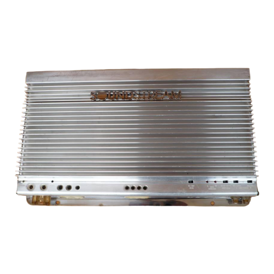
Soundstream REFERENCE A 10.0 Owners And Installation Manual

Soundstream REFERENCE A 10.0 Owners And Installation Manual

Soundstream technologies owners manual and installation guide stereo amplifier class a 5.0, class a 10.0
Hide thumbs Also See for REFERENCE A 10.0:

Advertisement

SERIES AND PARALLEL WIRING
REFERENCE
Class A
5.0 & 10.0

Power Amplifiers

2-4 ohm drivers in parallel
= 2 ohms

OWNERS MANUAL

AND

INSTALLATION GUIDE

4-4 ohm drivers in parallel
=1 ohm
2-4 ohm drivers in series
= 8 ohms
SOUNDSTREAM TECHNOLOGIES
120 Blue Ravine Road
Folsom
California 95630 USA
ph 916.351.1288
fax 916.351.0414
rev B - 4.17.96
20
1

Advertisement

Table of Contents
loading
Need help?

Need help?

Do you have a question about the REFERENCE A 10.0 and is the answer not in the manual?

Questions and answers

Summary of Contents for Soundstream REFERENCE A 10.0

  • Page 1: Power Amplifiers

    = 2 ohms OWNERS MANUAL INSTALLATION GUIDE 4-4 ohm drivers in parallel =1 ohm 2-4 ohm drivers in series = 8 ohms SOUNDSTREAM TECHNOLOGIES 120 Blue Ravine Road Folsom California 95630 USA ph 916.351.1288 fax 916.351.0414 rev B - 4.17.96...
  • Page 2: Specifications

    0.7 - 2.8 Q (0 to +9 dB), adjustment from 30 to 60 Hz Dimensions (W x D x H) REFERENCE CLASS A 5.0: 12.25” x 9.8” x 2.25” REFERENCE CLASS A 10.0: 15.0” x 9.8” x 2.25” SERVICE SPECIFICATIONS...
  • Page 3: Protection Circuitry

    Design Features ... 4 - 5 AIRBASS™ ... 5 Reference Class A 5.0 Diagram ... 6 - 7 Reference Class A 10.0 Diagram ... 8 - 9 Selecting Input Modes ... 10 Balanced / Unbalanced Input ... 11 CAUSE Wiring &...
  • Page 4: Design Features

    Frequency (Hz) FIG. 7 Various Settings NOTE: The LSE.Q circuit on the Class A 10.0 can be defeated for flat operation down to 20 Hz by placing the LSE.Q switch in the "OUT" position. You may wish to use this option to achieve a higher S/N Ratio...
  • Page 5 LSE.Q THEORY AND USE (Class A 10.0) LSE.Q is a unique subwoofer control circuit i n c l u d e d w i t h REFERENCE Class A 10.0 capable of removing subsonic energy in program material. The circuit consists of two controls.
  • Page 6: Installation Step

    Class A 5.0 INSTALLATION STEP 5 LEVEL SETTING The input levels are adjusted by means of the individual channel input level controls located on the front of the amplifier. This is a unique dual-stage circuit that adjusts both level and gain. This topology maintains better Signal to Noise ratios even when using sources with minimal output.
  • Page 7: Installation And Mounting

    INSTALLATION STEP 4 INSTALLATION AND MOUNTING 1. AMPLIFIER LOCATION The REFERENCE Class A amplifiers employ highly efficient circuitry and a unique Chassisink design to maintain lower operating temperatures. Additional cooling may be required if the amplifier is located in a tightly confined area or when driving especially low impedance loads at extremely high levels.
  • Page 8: Wiring Diagram

    REFERENCE Class A Amplifier Fuse Values Amplifier Amplifier Fuse 40 amp Maxi-Fuse Class A 5.0 Class A 10.0 80 amp Maxi-Fuse REMOTE TURN-ON Connect the “Remote” to the turn-on lead from the source unit. When +12 volts is received, the amplifier will turn on.
  • Page 9 10’ Soundstream Power40 or Class A 5.0 Power80 Soundstream Power40 only Class A 10.0 (4 ga.) Read this, or sparks will fly! The Soundstream REFERENCE Class A amplifiers have extensive internal power supply capacitance, called the Ultra-Low ESR Capacitance Bank.
  • Page 10: Balanced / Unbalanced Input

    INSTALLATION STEP 1 COHERENT STEREO™ / MIXED-MONO / BRIDGED MONO The REFERENCE Class A amplifiers have the ability to operate in any one of the following modes: Coherent Stereo™ with identical left and right stereo channels for maximum fidelity. Best choice for satellite speakers. Use this mode unless Mixed-Mono is necessary.

Table of Contents

Save PDF