Table of Contents
Advertisement
Advertisement
Table of Contents

Subscribe to Our Youtube Channel
Related Manuals for Peak AMGO PX12


Summary of Contents for Peak AMGO PX12
- Page 1 PX12/PX12A (X550/X550A)
-
Page 2: Table Of Contents
CONTENTS Product Features and Specifications ............1 Installation Requirement ...............3 Steps of Installation ................4 Exploded View ..................23 Test Run ....................28 Operation Instruction ................29 Maintenance ..................30 Trouble Shooting ................32 Parts List ..................33... -
Page 3: Product Features And Specifications
I. PRODUCT FEATRUES AND SPECIFICATIONS Professional Alignment Scissors Lift Model PX12A(X550A) · Electric- air control system, safety self-lock mechanism · 2-Dual synchronous cylinders are applied to assure the lifting level on both platforms · Non-skid diamond runway · Integrated rear slip-plates ·... - Page 4 Professional non-alignment Scissors Lift Model PX12(X550) · Electric- air control system, safety self-lock mechanism · Dual synchronous cylinders are applied to assure the lifting level on both platforms · Non-skid diamond runway; supper wide platform · Heavy duty design, fit for a wide range of vehicle car to van and truck ·...
-
Page 5: Installation Requirement
INSTALLATION REQUIREMENT A. TOOLS REQUIRED Rotary Hammer Drill Carpenter’s Chalk (Φ19, Φ10, Φ4,) Hammer Screw Sets Level Bar Tape Measure (7.5m) English Spanner (12") Pliers Ratchet Spanner With Socket (28 Lock Wrench ... -
Page 6: Iii. Steps Of Installation
B.SPECIFICATIONS OF CONCRETE Specifications of concrete must be adhered to the specification as following. Failure to do so may result in lift and/or vehicle falling. 1.Concrete must be thickness 100mm minimum and without reinforcing steel bars, and must be dried completely before the installation. 2 .... -
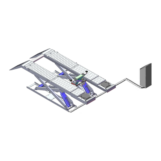
Page 7: Illustration Of Scissors Lift Px12(X550) On Surface Installation (See Fig
Illustration of scissors lift PX12(X550) on surface installation (See Fig.5). Fig. 5 Illustration of scissors lift PX12A(X550A) on surface installation (See Fig.6). Fig. 6... - Page 8 2. For Optional Installation: Flush mount installation 2.1 Flush mount installation foundation (Fig.7) Power input 4*2.5 Hydraulic system, limit switch , Air source input φ50 PVC Tube Fig. 7 Illustration of scissors lift PX12(X550) with flush mount installation (Fig.8). Fig. 8...
- Page 9 Illustration of scissors lift PX12A(X550A)with flush mount installation (Fig.9). Fig. 9 B. Check the parts before assembly. 1. Packaged lift and control cabinet (See Fig. 10). Fig. 10...
- Page 10 2. Move aside the lift with fork lift or hoist, and open the outer packing carefully. 2.1 Parts for on surface installation (See Fig.11, Fig.12) For Model PX12A(X550A) Fig. 11 For Model PX12(X550) Fig. 12...
- Page 11 2.2 Parts for flush mount installation (See Fig.13, Fig.14) guide ramp Noted: Need for flush mount installation For Model PX12A(X550A) Guide ramp (510018) Fig. 13 For Model PX12(X550) Guide ramp (510019) Fig. 14...
-
Page 12: See Fig.
3. Open the parts box, check the parts according to the part list (See Fig.15, Fig.16 ). For PX12A(X550A) For PX12(X550) Fig. 15 Fig. 16 4. Check the parts of the parts bag according to the parts bag list 4.1 Parts bag for on surface installation (See Fig.17, Fig.18) For PX12A(X550A) Fig. - Page 13 4.2 Parts bag for flush mount installation (See Fig.19, Fig.20) For PX12A(X550A) Fig. 19 For PX12(X550) Fig. 20 C. Layout the machine and install oil system and air line system. 1. Select a location and layout the equipment according to steps A (See Fig.
- Page 14 For Model PX12(X550) Fig. 22 2. Connecting the oil hose and air line Control cabinet installed in the left of the car in direction (See Fig. 23). Connect the A of Air solenoid valve ○ 1 5/16*4450mm ○ 4 5/16*5860 mm ○...
- Page 15 2.2 Control cabinet installed in the right of the car in direction (See Fig. 24). Oil hose fixing slot Connect the A of Air solenoid valve hose must through the oil hose Fig. 24 fixing slot 3. Install the oil-water separator (See Fig.
- Page 16 4. Connect the air source (air pressure 5kg/cm -8kg/cm ), Adjust the air pressure to 0.4~0.6MPa (See Fig. 26). Connect air source Adjust the air pressure to 0.4~0.6MPa Clockwise to increase the air pressure Counter-clockwise to reduce the air pressure Fig.
- Page 17 2. Wire connection for hydraulic power unit (380V) 2.1 Connect the power wire and limit switch wire according to the Wiring diagram (See Fig. 28). Earth Wire Power Wire Hydraulic Low Limit High Limit Motor Wire Solenoid Valve switch switch Fig.
- Page 18 3. Wire connection for hydraulic power unit (220V) 3.1 Connect the power wire and limit switch wire according to the Wiring diagram (See Fig. 30) Hydraulic Low Limit High Limit Motor Wire Earth Wire Power Wire Solenoid Valve Switch Switch Fig.
- Page 19 E. Level two platforms and install anchor bolts. 1. Check by level bar, adjust the down leveling bolts(see fig.32B) and add the shim until two platforms are in the same level, lowering the lift to the lowest position and adjust the up leveling bolts (see fig.32A) until contacting the down leveling bolts, tighten the nut with wrench.
- Page 20 F. Install runway connecting bar (See Fig. 35). Fig. 35 G. Install oil hose cover for on surface installation. 1. Tidy up the oil hose and air line, cover the oil hose cover (See Fig. 36). Using the colloidal screw to fasten the Fig.
- Page 21 H. Illustration of installing the PX12(X550)/PX12A(X550A) optional air line kits(Fig.38) 90 fitting Air source 12-30 Fig. 38...
- Page 22 1. Connect the air line fittings with 8*6 black air line (The length of air line can be cut accordingly) (Fig.39) Fig. 39 Ø8*Ø6Air line Air Source Oil-water View B separator View A...
- Page 23 2. First replace the 90°air line fitting on the oil-water separator by the T fitting; Then pass the 8*6 black air line through control cabinet and connect it to the upper end of T fitting. (see View A) 3. Pass the 8*6 black air line through the hole of base and oil hose fixing slot on the outer scissors.
- Page 24 Air line 101 102 Air line Ø8*Ø6Air line View H View G 7. Connect the female fitting of air line and to the male quick fitting on air pump of the two rolling jacks. (see View I) Air pump View I...
-
Page 25: Exploded View
EXPLODED VIEW MODEL PX12A(X550A) Optional Turnplate Fig. 40... - Page 26 MODEL PX12(X550) Fig. 41...
- Page 27 CYLINDERS grease lubricate regularly grease lubricate regularly Fig. 42...
- Page 28 CONTROL CABINET Fig. 43...
- Page 29 PEAK ELECTRIC POWER UNIT 220V/50HZ/1Phase 380V/50HZ/3 Phase Fig. 44...
-
Page 30: Test Run
TEST RUN 1. Fill oil adjustment a. Turn on the power after connecting oil system correctly. Press the button Up, and check the rotated direction of the motor (This is right if lift is upward, otherwise, it is wrong direction of the motor). Shut off power and exchange the phase connection if the direction is wrong. -
Page 31: Operation Instruction
c. Push button “UP” and the Red Button beside the oil-water separator as to fill Fig. 45 the oil into both secondly cylinders until it is full (to the highest position). d. Turn both handle of the shutoff valves to normal working position push (See Fig. -
Page 32: Maintenance
VII. MAINTENANCE SCHEDULE Monthly: 1. Re-torque the anchor bolts to 150 Nm. 2. Check all fittings, bolts and pins to insure proper mounting. Note: All anchor bolts should take full torque. If any of the bolts does not function for any reason, DO NOT use the lift until the bolt has been replaced. 3. - Page 33 For Secondly Cylinder For shaft of piston rod of Fig.53 Secondly cylinder Fig.54 Every six months: 1. Make a visual inspection of all moving parts for possible wear, interference or damage. 2. Check and adjust the platform as necessary to insure level lifting. 3.
-
Page 34: Trouble Shooting
VIII.TROUBLE SHOOTING TROUBLE CAUSE REMEDY 1.Button does not work 1. Replace button 2.Wiring connections are not in good 2. Repair all wiring connection condition Motor does not run 3. AC contactor burned out 3. Replace AC contactor 4. Motor burned out 4. -
Page 35: Parts List
IX. PARTS LIST For Model PX12A(X550A), PX12(X550) Note Item Part# Description PX12A PX12 520003 Shelf assy. 530002A Inner Scissors 530003A Outer Scissors 520011 Air Cylinder 420153 Cup Head Bolt 510034 Hex Bolt 510040 Limit switch assy. 520013 Connecting Pin 206032 Snap Ring 520015C Base frame... - Page 36 Qty. Item Part# Description Note PX12A PX12 420157 Steel Ball 570003 Rear Slip Plate 520037 Pin for Rear Slip Plate Plate for Adjustable Turnplate 560003 530001B Runway Connecting Bar 206023B Hex Nut 420026 Lock Washer 206006 Washer 420136 Hex Bolt 520005A Drive-in Ramp(On surface/Flush mount) 510004A...
- Page 37 Item Part# Description Note 420146 Straight Fitting for air line 680005 Cup Head Bolt 420097 90° Fitting 510024 Fitting 550003 Power unit 440009 Straight Fitting for power unit 206062 Straight Fitting 630103 Straight Fitting 61K107 T- Fitting 61K050 Hex Bolt 209033 Washer 209005...
- Page 38 Parts For Main Cylinder 11-1 530032 Main Cylinder 11-2 530025 O- Ring 11-3 530033 Head Cap(Main) 11-4 530028 Support Ring 11-5 530024 Y- Ring 11-6 530026 Dust Ring 11-7 530034 Piston Rod (Main) 11-8 520054 O- Ring 11-9 530027 Support Ring 11-10 520063 Y- Ring...
- Page 39 420077 Bleeding plug 12-28 201034 Transformer (TC) 12-29 420134 540008 Protected Ring 12-30 420142 Lowering Alarm Button (k) 12-31 Parts For PEAK Electric Power Unit 220V/50HZ/1 Phase QTY. Item Part# Description Note PX12A PX12 81400199 72-1 Motor 81400208 72-2 Cover of Motor Terminal Box...
- Page 40 Parts For PEAK Electric Power Unit 380V/50HZ/3 Phase QTY. Item Part# Description Note PX12A PX12 81400201 72A-1 Motor 81400209 72A-2 Cover of Motor Terminal Box 81400178 72A-3 Protect Ring 680005 72A-4 Cup Head Bolt 81400192 72A-5 Check Valve 81400196 72A-6...
- Page 41 72115304 01/2017...
Need help?
Do you have a question about the AMGO PX12 and is the answer not in the manual?
Questions and answers