Table of Contents
Advertisement
Quick Links
Advertisement
Table of Contents

Subscribe to Our Youtube Channel
Related Manuals for Peak PX09


Summary of Contents for Peak PX09
- Page 1 PX09/PX09A (X400/X400A)
-
Page 2: Table Of Contents
CONTENTS Product Features and Specifications ............1 Installation Requirement ...............3 Steps of Installation ................4 Exploded View ..................19 Test Run ....................25 Operation Instruction ................26 Maintenance ..................26 Trouble Shooting ................28 Parts List ..................29... -
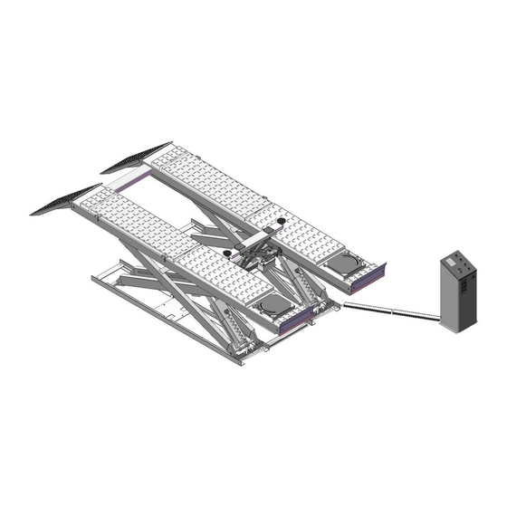
Page 3: Product Features And Specifications
I. PRODUCT FEATRUES AND SPECIFICATIONS Professional Alignment Scissors Lift Model PX09A(X400A) · Electric- air control system, mechanical safety locks · Dual synchronous cylinders are applied to assure the lifting level on both platforms · Skid proof diamond platform. · Integrated rear slip-plates ·... - Page 4 · Sand resistance platform to avoid skidding · Heavy duty design, fit for a wide range of vehicle car to van and truck · Optional Jack (with hand pump/air-operated hydraulic pump) Fig. 2 MODEL PX09 SPECIFICATIONS Distance Overall Lifting Lifting Min.
-
Page 5: Installation Requirement
INSTALLATION REQUIREMENT A. TOOLS REQUIRED Rotary Hammer Drill Carpenter’s Chalk (Φ19, Φ10, Φ4,) Hammer Screw Sets Level Bar Tape Measure (7.5m) English Spanner (12") Pliers Ratchet Spanner With Socket (28 Lock Wrench ... -
Page 6: Iii. Steps Of Installation
III. STEPS OF INSTALLATION A. Location of Installation Check and insure the installation location (concrete, layout, space size etc.) is suitable for lift installation. 1. For Standard Installation: On surface installation PX09/PX09A(X400/X400A) On surface installation foundation (See Fig. 4) Fig. 4... - Page 7 1.2 Illustration of scissors lift PX09(X400) on surface installation (See Fig.5). Fig. 5 1.3 Illustration of scissors lift PX09A(X400A) on surface installation (See Fig.6). Fig. 6...
- Page 8 2. For Optional Installation: Flush mount installation 2.1 Flush Mount Installation Foundation (Fig.7). Power input 4*2.5 Air source input φ50 PVC Tube Fig. 7 2.2 Illustration of scissors lift PX09(X400) flush mount installation (Fig.8). Fig. 8...
- Page 9 2.3 Illustration of scissors lift PX09A(X400A) flush mount installation (Fig.9). Fig. 9 B. Check the parts before assembly. 1. Packaged lift and control cabinet (See Fig. 10). Fig. 10...
- Page 10 2. Move aside the lift with fork lift or hoist, and open the outer packing carefully 2.1 Parts for lift of on surface installation (See Fig.11, Fig.12) For Model PX09A(X400A) Fig. 11 For Model PX09(X400) Fig. 12...
- Page 11 2.2 Parts for lift of flush mount installation (See Fig.13, Fig.14) Note: Need guide ramps for flush mount installation For PX09A(X400A) Guide ramp (510018) Fig. 13 For PX09(X400) Guide ramp (510019) Fig. 14...
- Page 12 3. Open the parts box, check the parts according to the part list (See Fig. 15, Fig.16). PX09(X440) parts box PX09A(X440A parts box Fig. 16 Fig. 15 4. Check the parts of the parts bag according to the parts bag list 4.1 Pasts bag for lift of on surface installation...
- Page 13 4.2 Parts bag for lift of flush mount installation (See Fig.19, Fig.20) For Model PX09A(X400A) Fig. 19 For Model PX09(X400) Fig. 20 C. Layout the model and install oil system and air line system. 1. Select a location and layout the model according to steps A (See Fig.
- Page 14 For Model PX09(X400) Fig. 22 2. Connecting the oil hose and air line (See Fig. 23). Connect to the A of Air solenoid valve ○ ,1Hose 1/4*2240 ○ ,2Hose 1/4*4860 ○ ,3Hose 1/4*4860 Fig. 23...
- Page 15 3. Install the oil-water separator (See Fig. 24). 12-11 12-8 Connect the air source by the oil-water separator Fig. 24 4. Connecting the air source (air pressure 5kg/cm - 8kg/cm ), adjust the air pressure to 0.4- 0.6MPa (See Fig. 25). Connecting air source Adjust the air pressure...
- Page 16 D. Install electric system 1. Adjusting the current rating of thermal relay in control box according to the different configurations of hydraulic power unit. In general, the electric current of thermal relay should equal or larger than that of motor. The following table shows rated current regulation of thermal relay in case of different hydraulic power unit.
- Page 17 2.2 Circuit Diagram (See Fig. 28). 3 phase Fig. 28 Electric Component Item Name Code Specification Item Name Code Specification Power switch 380V AC Push button Duplex Fuse Push button LOCK Duplex Fuse Push button Triple Down1 AC contactor 24V AC Push button Down2 Duplex...
- Page 18 3.2 Circuit Diagram (See Fig. 30). Single phase Fig. 30 Electric Component Item Name Code Specification Item Name Code Specification Power switch 380V AC Push button Duplex Fuse Push button LOCK Duplex Fuse Push button Down1 Triple AC contactor 24V AC Push button Down2 Duplex...
- Page 19 2. Install anchor bolts. 2.1 Raise the lift to 1000mm then drill holes to install the anchor bolts (See Fig.32). Using the anchor bolt control cabinet Using the anchor bolt to fix the model Fig. 32 2.2 Fix the anchor bolts. Drilling the hole for the anchor bolt with the rotary hammer drill, type the anchor bolt into the ground, and then fasten it with ratchet spanner (See Fig.
- Page 20 F. Install runway connecting bar (See Fig. 34). Fig. 34 G. Install oil hose cover for lift of on surface installation. 1. Tidy up the oil hose and air line, cover the oil hose cover (See Fig. 35). Using the colloidal screw to fasten the Fig.
-
Page 21: Exploded View
EXPLODED VIEW MODEL PX09A(X400A) Optional Turnplate Fig. 37... - Page 22 MODEL PX09(X400) Fig. 38...
- Page 23 CYLINDERS Add grease to lubricate regularly Add grease to lubricate regularly Fig. 39...
- Page 24 CONTROL CABINET Fig. 40 SPX ELECTRIC POWER UNIT 220V/50HZ/1PH Fig. 41...
- Page 25 PEAK ELECTRIC POWER UNIT 220V/50HZ/1Phase 380V/50HZ/3 Phase Fig. 42 Illustration of hydraulic valve for SPX & PEAK hydraulic power unit SPX Electric power unit, 220V/50HZ, Single phase (See Fig. 43) Capacitor Relief valve Oil return port Solenoid valve Auxiliary hole...
- Page 26 Oil return port Solenoid valve Throttle valve Check valve Oil Outlet Fig. 44 Fig. 50 C. PEAK electric power unit, 380V/50HZ, 3 phase (See Fig. 45) Relief valve Oil return port Solenoid valve Throttle valve Oil outlet Check valve Fig. 45...
-
Page 27: Test Run
TEST RUN A. Fill oil to cylinder 1. Turn on the power, press the button Up, and check the rotated direction of the motor(This is right if lift is upward, otherwise, it is wrong direction of the motor). Shut off power and exchange the phase connection if the direction is wrong, and then follow the following procedure of filling oil to cylinders. -
Page 28: Operation Instruction
VI. OPERATION INSTRUCTIONS To lift vehicle 1. Keep clean of site near the lift, and down the lift to the lowest position. 2. Drive vehicle to the platform and put on the brake. 3. Turn on the power and press the button Up, raise the lift to the working position. Note: make sure the vehicle is steady when the lift is rising 4. - Page 29 For pins of connecting platforms and scissors Fig. 51 For connecting pins of scissors Fig.52 3. Check all fittings, bolts and pins to insure proper mounting. 4. Make a visual inspection of all hydraulic hoses/lines for possible wear or leakage. 5.
-
Page 30: Trouble Shooting
VIII.TROUBLE SHOOTING TROUBLE CAUSE REMEDY 1.Button does not work 1. Replace button 2.Wiring connections are not in good 2. Repair all wiring connection condition Motor does not run 3. AC contactor burned out 3. Repair or replace contactor 4. Motor burned out 4. -
Page 31: Parts List
IX. PARTS LIST For Model PX09A (X400A) , PX09 (X400) Item Part# Description Note PX09 PX09A (X400) (X400A) (See Fig.37-38, Fig.5-6, Fig.23-24, Fig.11-14, Fig.32-36, Fig.40) 520003 Shelf 520009B Inner Scissors 520010B Outer Scissors 520011 Air Cylinder 420017 Cup Head Bolt... - Page 32 Item Part# Description Note PX09 PX09A (X400) (X400A) 520001D Powerside Platform 510001D 510020 Runway Connecting Bar 420157 Steel Ball 520036A Rear Slip Plate 560003 Plate for Adjustable Turnplate 520037 Pin For Slip Plate 420136 Hex Bolt 206006 Washer 420026 Lock Washer...
- Page 33 Item Part# Description Note PX09 PX09A (X400) (X400A) 620070 Colloidal screw 620069 Wood screw 420019 Power Unit 440009 Straight Fitting For Power Unit 52K027 90 Fitting 420097 90 Fitting 61K018 Two-way Valve Parts box(On surface installation) 520500A Parts box(On surface installation)...
- Page 34 Parts List For Control Cabinet (See Fig. 40) Note Item Part# Description PX09 PX09A (X400) (X400A) Button UP 12-1 420071 Button LOCK 12-2 420071 Button DOWN 1 12-3 420072 Button DOWN 2 12-4 420142 12-5 52K001B Control Panel 12-6 420074...
- Page 35 200-24 420070 Check Valve 200-25 209106 Gear Pump 200-26 209107 Oil Return Pipe 200-27 209108 Filler Cap Parts For PEAK Electric Power Unit 220V/50HZ/1 Phase (See Fig.42) 200A-1 209082A Motor 200A-2 209083A Motor Connecting Shaft 200A-3 209084A Valve Body 200A-4...
- Page 36 209117A Release Valve Adjusting Rod 200A-26 209106A Gear Pump 200A-27 209107A Oil Return Pipe 200A-28 209108A Filler Cap Parts For PEAK Electric Power Unit 380V/50HZ/3 Phase (See Fig.42) 200B-1 209118 Motor 200B-2 209083A Motor Connecting Shaft 200B-3 209084A Valve Body...
- Page 37 72215102 06/2013...
Need help?
Do you have a question about the PX09 and is the answer not in the manual?
Questions and answers