Thetford SHB981 Series User And Installation Instructions Manual
Build-in cooking hob topline hybrid glass hobs. for use with mains electricity and universal lpg
Hide thumbs
Also See for SHB981 Series:
- Installation manual (12 pages) ,
- Installation manual (129 pages)
Advertisement
Quick Links
Build-in cooking hob
Topline hybrid glass hobs
SHB981XXZ Series dual fuel
For use with mains electricity and Universal LPG
User and installation instructions
Please read and keep for future reference
For use in Australia
THETFORD AUSTRALIA PTY LTD
41 LARA WAY CAMPBELLFIELD VIC
TEL: 03 9358 0700
FAX: 03 9357 7060
www.thetford-europe.com
INS1021Z -0-
1
Advertisement

Related Manuals for Thetford SHB981 Series


Summary of Contents for Thetford SHB981 Series
- Page 1 For use with mains electricity and Universal LPG User and installation instructions Please read and keep for future reference For use in Australia THETFORD AUSTRALIA PTY LTD 41 LARA WAY CAMPBELLFIELD VIC TEL: 03 9358 0700 FAX: 03 9357 7060 www.thetford-europe.com...
- Page 2 CAUTION • Appliance and accessible parts become hot during use. Avoid touching the heating elements or pan supports when in use. • The use of a gas cooking appliance results in the production of heat, moisture and products of combustion in the room in which it is installed.
- Page 3 CAUTION • Do not modify this appliance. Do not make any adjustments unless such work is carried out by authorized personnel, the manufacturer or their representative. No parts other than those supplied by the manufacturer shall be used on this appliance. •...
- Page 4 INTRODUCTION This appliance is designed for cooking foods and any other use is incorrect and may be dangerous. Failure to install the appliance correctly or improper use will invalidate any warranty or liability claims. This appliance must only be installed by a qualified installer or engineer in accordance with the relevant local and national regulations in force.
- Page 5 OPERATION OF THE GAS BURNERS The burners are controlled individually and each is monitored by a thermocouple probe. In the event the burner flames are accidentally extinguished, turn off the burner control and do not attempt to re-ignite the burner for at least one minute. Ensure gas and electric supply is connected and turned on.
- Page 6 • Avoid old or miss-shaped pans as these may cause instability. Using excessively large pans may reduce performance or cause • damage. GLASS SYMBOL DESCRIPTIONS Do not remove the pan support and enclose the burner with a wok stand as this will concentrate and deflect heat onto the hotplate Do not place anything, e.g.
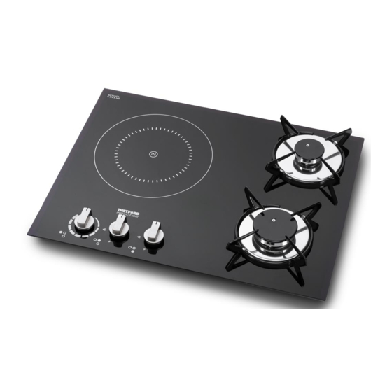
- Page 7 OPERATION OF THE INDUCTION HOB The induction heating zone is marked with a circular dotted line with the symbol ‘IN’ at the centre. Please ensure, regardless of pan type (stainless, enameled steel, cast iron, etc) the pan base is smooth and flat to avoid the risk of scratching the glass. Never slide the pan across the glass surface, lift the pan to avoid scratches.
- Page 8 Switching On: Place a suitable pan containing food or water on the induction heating zone. The induction heater is switched on when the control knob is rotated clockwise from power level ‘0’ position to any higher position. When the heater is activated the red LED light is illuminated to indicate the power setting from ‘1’, lowest power, to ‘9’...
- Page 9 Automatic Heat-up: This function allows rapid heat up of the induction zone, with automatic reduction to a preset level once the desired temperature is reached. To activate, with a suitable pan in position and the control set to ‘0’, rotate the control knob anti-clockwise briefly until ‘A’ is shown in the LED display, then rotate the knob immediately clockwise to the desired pre-set power level.
- Page 10 LED Indication of Fault or Error Codes. If the following Symbol┌┘ or letter is displayed followed by a number, this indicates that the appliance has developed an internal technical fault. Switch off the appliance at the power supply. If the fault indication does not clear when mains power is restored then it cannot be rectified by the user.
-
Page 11: Care And Maintenance
Servicing and maintenance must only be performed by authorized and suitably qualified personnel. Refer to your local Thetford Service agent giving details of the model & Serial No. from the appliance Data Badge. - Page 12 Consumption Spark Ignition 12 Volt DC Gas; Universal LPG – 2.75 kPa ELECTRICAL ENERGY CONSUMPTION MEASUREMENT AND CALCULATIONS IN ACCORDANCE WITH IEC 60350-2 2013. Type of Diameter of Energy Thetford Appliance Cooking Cooking Consumption Model Identification Zones (Watts) Zone Wh/kg electric hob 1.4 kW...
-
Page 13: Installation
INSTALLATION Fig 2a Worktop Cut-Out Details SHB981XXZ Series The worktop cut-out and fixing holes must be prepared to the dimensions shown below. 4 X Ø10mm fixing holes required... - Page 14 INSTALLATION Regulations and Standards In the interest of safety, it is a legal requirement that all gas and electrical appliances are only installed and serviced by an approved competent person, in accordance with the local and National standards in force. Failure to install the appliance correctly will invalidate any warranty or liability claims and may lead to prosecution.
- Page 15 INSTALLATION Fig 4 - Cross Section View of Appliance Mounted in a Worktop 30mm Minimum air gap from lowest part under the hob. Non – combustible material. Vent – 8mm x 100mm minimum. Gas dispersal hole (Ø12mm Minimum, Ø25mm Maximum). Ventilation This appliance is suitable for installation into Holiday Homes, Touring Caravans and Boats.
- Page 16 INSTALLATION Position A cutout should be prepared as shown in the enclosed diagrams – see Fig. 2 and Fig.2a for model cutout details. We recommend the underside of the hob be shielded, particularly if this area is to be used for storage or the installation of another appliance.
- Page 17 INSTALLATION This appliance must be positioned free from draughts, which may affect the combustion, and in a manner that will prevent the accumulation of unburnt gas. When in use ensure that air vents are not inadvertently blocked or shut off. If other appliance/s are located below the hob we recommend conducting a temperature verification test to confirm any rise in temperature of the cabinet materials are within allowable limits and meet requirements specified in AS 4551-...
- Page 18 In the event that this appliance cannot be adjusted to perform correctly and for any service assistance, please contact your authorised Thetford Service Agent giving details of the model and serial number from the data badge on the...
- Page 19 After any service or maintenance work the appliance must be checked for both electrical safety and gas soundness. Thetford Ltd does not accept responsibility for loss or injury caused directly or indirectly by incorrect use of this appliance. In accordance with our policy of product development we reserve the right to amend designs and specifications without prior notice.
- Page 20 Unscrew and/or unclip the spark generator and lift off the unit. Replace/refit using reverse procedure. Induction Components A Thetford approved Service Agent must be consulted if any induction components require removal or replacement. The induction control circuits and coils are not user serviceable and are sensitive to electrostatic discharge.
- Page 21 ┌┘on LED Display shows E or Disconnect electric supply and refer to Internal fault detected. start up Thetford approved Service Agent. Residual heat LED Display shows ‘H’ after This is normal, allow the appliance to detected, glass cool after use.
- Page 22 Fig 6. Mains Wiring Diagram...
Need help?
Do you have a question about the SHB981 Series and is the answer not in the manual?
Questions and answers