Table of Contents
Advertisement
Quick Links
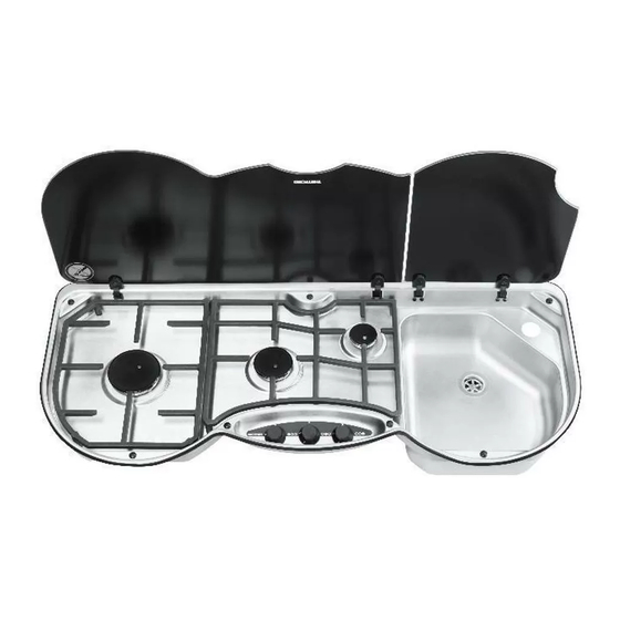
Build-In Cooking Hob
SHB353XXZ Series Hobs
SCU353XXXZ Series Combination Hobs
For use with Universal LPG
User and installation instructions
Please read and keep for future reference
For use in Australia
Original Instructions
THETFORD AUSTRALIA PTY LTD
41 LARA WAY CAMPBELLFIELD VIC
TEL: 03 9358 0700
FAX: 03 9357 7060
www.thetford-europe.com
Advertisement
Table of Contents

Related Manuals for Thetford SHB353XXZ Series


Summary of Contents for Thetford SHB353XXZ Series
- Page 1 Build-In Cooking Hob SHB353XXZ Series Hobs SCU353XXXZ Series Combination Hobs For use with Universal LPG User and installation instructions Please read and keep for future reference For use in Australia Original Instructions THETFORD AUSTRALIA PTY LTD 41 LARA WAY CAMPBELLFIELD VIC...
- Page 2 CAUTION • Appliance and accessible parts become hot during use. Avoid touching the heating elements or pan supports. • The use of a gas cooking appliance results in the production of heat, moisture and products of combustion in the room in which it is installed.
- Page 3 CAUTION • Do not allow cooking vessels to overlap the edges of the appliance – use the correct sizes of pans and position them centrally over the burners. • Do not use harsh abrasive cleaners or sharp metal scrapers to clean the glass since they can scratch the surface, which may result in shattering of the glass.
-
Page 4: Appliance Dimensions And Specifications
APPLIANCE DIMENSIONS AND SPECIFICATIONS APPLIANCE SHB353XXZ SERIES APPLIANCE SCU353XXXZ SERIES (mm) (mm) (mm) (mm) (mm) (mm) Gas Input & Injector Size Gas Input & Injector Size SHB353XXZ SCU353XXXZ MJ/hr MJ/hr SERIES SERIES 0.52 0.52 1.75 0.67 1.75 0.67 0.82 0.82 5.25... - Page 5 Fig. 1 - WORKTOP CUTOUT – SHB353XXZ Series...
- Page 6 Fig. 2 – WORKTOP CUTOUT – SCU353XXXZ Series...
- Page 7 Fig. 3 - SURFACE MOUNT FIXING – SHB & SCU 353 SERIES EDGE DETAIL Fix the hob centrally in the cut-out to maintain a 2-3mm air gap to the worktop. Surface mounting bezel Pressing Glass Lid Screw fixing cap Bump Stop Wood Screw Worktop Fig.
- Page 8 Fig. 5 – Air Gap and Gas Dispersal Hole A = 58mm Air gap beneath hob pressing. B = Gas dispersal hole. Min Ø 12mm, max Ø 25mm, with baffle & grille, venting to outside. Fig. 6 – Control Positions FULL RATE LOW RATE Fig.
-
Page 9: Burner Operation
INTRODUCTION This appliance is designed for cooking foods and any other use is incorrect and may be dangerous. Failure to install the appliance correctly or improper use will invalidate any warranty or liability claims. This appliance must only be installed by an approved and competent person, in accordance with the local Regulations in force. -
Page 10: Operation
They are interchangeable without affecting the sense of operation. If any replacement parts are required they must be obtained by contacting Thetford Ltd at the address or telephone number shown in this manual. -
Page 11: Installation
INSTALLATION Regulations and Standards Read the instructions before installing this appliance and comply with the cautions and warnings section on Page 2 & 3 of this manual. Gas appliances must only be installed and serviced by an approved and competent person. Failure to install the appliance correctly could invalidate any warranty or liability claims and may lead to prosecution. - Page 12 INSTALLATION Care should be taken to position the appliance centrally in the worktop cut-out to ensure an air gap is maintained between the edges of the appliance and the sides of the cut-out. The appliance may then be fixed in position with screws - see Fig. 3. Make sure the appliance is level and correctly positioned in the aperture before fixing in place.
- Page 13 INSTALLATION Electrical Connection The spark ignition generator must only be connected to a suitable 12V DC battery. Sheathed spade connectors should be used to connect the spark generator to the power supply. To ensure correct operation observe the following installation requirements: •...
- Page 14 Hob burner injector removal/replacement. Lift off the appropriate pan rest to release it from the rubber bushes. Remove the screw in the burner cap and lift off the burner cap and skirt / flame spreader. With a 7mm A/F socket, unscrew the injector from the bottom of the burner mixing tube. Replace/refit using the reverse of the above procedure.
- Page 15 In accordance with our policy of ongoing product development, specifications may change without prior notice. THETFORD AUSTRALIA PTY LTD 41 LARA WAY CAMPBELLFIELD VIC TEL: 03 9358 0700...
Need help?
Do you have a question about the SHB353XXZ Series and is the answer not in the manual?
Questions and answers