Table of Contents
Advertisement
Quick Links
USER AND INSTALLATION INSTRUCTIONS
USER AND INSTALLATION INSTRUCTIONS
FOR USE IN :-
GB, IE, FR, NL, BE, LU, ES, IT, NO, DE, DK, SE
WARNING
• Read the instructions before use.
• Only use this appliance in a well ventilated area.
• This appliance must be installed in accordance with the regulations in force.
THETFORD LIMITED, 19 Oakham Drive, Parkwood Industrial Estate
Rutland Road, Sheffield S3 9QY, ENGLAND.
TEL: + 44 (0) 114 273 8157
FAX: + 44 (0) 114 275 3094
Advertisement
Table of Contents

Subscribe to Our Youtube Channel
Related Manuals for Thetford S-HB33000


Summary of Contents for Thetford S-HB33000
- Page 1 • Only use this appliance in a well ventilated area. • This appliance must be installed in accordance with the regulations in force. THETFORD LIMITED, 19 Oakham Drive, Parkwood Industrial Estate Rutland Road, Sheffield S3 9QY, ENGLAND. TEL: + 44 (0) 114 273 8157...
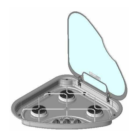
- Page 2 ITEM PART No DESCRIPTION ITEM PART No DESCRIPTION S~G930.BK GLASS LID S~PCC0691 PAN SUPPORT S~PCC0833 RAPID BURNER CAP S~PCC0832 RAPID BURNER SPREADER S~PCC2003 HINGE S~PCC0813 BURNER CAP S~PCC0812 BURNER SPREADER S~PCC1500 STICK ON FASCIA S~PCX0390 BUMP STOP S~PCC0647 PAN SUPPORT CLIP S~PCX0415 FIXING BUSH S~PCX0416...
- Page 3 ITEM PART No DESCRIPTION ITEM PART No DESCRIPTION S~G0940 GLASS LID S~PCC0693 PAN SUPPORT S~PCC0813 BURNER CAP S~PCC0814 BURNER SPREADER S~PCX0390 BUMP STOP S~PCX0415 FIXING BUSH S~PCC2003 HINGE S~PCC647 CLIP, PAN SUPPORT S~PCC1500 STICK ON FASCIA S~PCX0416 CLAMPING ARM S~PCC0609 CONTROL KNOB S~PCC0742 TAP FIXING NUT...
- Page 4 CONTROL POSITIONS – ALL MODELS FIG. 1 FULL RATE LOW RATE RECOMMENDED PAN SIZES FIG 2 SERIES 330 SERIES 340 & 345...
-
Page 5: Appliance Location
APPLIANCE LOCATION Series 330, 340 & 345 the minimum allowable distance to combustible materials is as shown below FIG. 3 A= 200mm unless protected by a non-combustible heat barrier B = 500mm minimum to fitment above appliance... - Page 6 Fig. 4 WORKTOP CUTOUT – SERIES 330 A = Surface Mount Cutout B = Flush Mount Cutout...
- Page 7 Fig. 5 WORKTOP CUTOUT – SERIES 340 A = Surface Mount Cutout B = Flush Mount Cutout...
- Page 8 SURFACE MOUNT FIXING – SERIES 330, 340 & 345 FIG. 6 Surface mounting bezel Glass Lid Bump stop Clamping bush Worktop Clamping arm Clamping screw Pressing Flush mounting bezel FIG. 7 FLUSH MOUNT FIXING – SERIES 330, 340 & 345 An additional 6mm deep rebate MUST be cut into the worktop to accept the ‘Flush Mounting Bezel’.
- Page 9 CONTENTS User’s Section Specification ……………………………………………………Page 8 Introduction ……………………………………………………Page 9 Using the Appliance ……………………………………………………Page 10 Installation and Servicing Installation Dimensions ……………………………………………………Pages 4-7 Specification ……………………………………………………Page 8 Installation Instructions ……………………………………………………Page 12 Maintenance & Servicing ……………………………………………………Page 13 Specification Series 330 Series 340 Series 345 MODEL S~HB33000 S~HB34000...
- Page 10 INTRODUCTION This appliance is designed for cooking food, any other use is incorrect and dangerous. Failure to install the appliance correctly or improper use could invalidate any warranty or liability claims and lead to prosecution. This appliance must be installed in accordance with the local, national and European regulations in force.
- Page 11 OPERATION WARNING • When cooking, young children should be kept away. • Glass lids may shatter when heated. Turn off all burners before shutting the lid. • Spillage on the lid surface should be removed before opening the lid Burner Operation The burners on the appliance have fixed aeration and no adjustment is required.
-
Page 12: Operation
OPERATION WARNING The Glass lid has the tendency to snap shut towards the end of lowering. This is caused by the travel lock action of the hinges as it is activated. Make sure all fingers are removed from appliance when closing the lid. DO'S AND DON'TS read the user instructions carefully before using the appliance for the first time. -
Page 13: Location Of Appliance
INSTALLATION REGULATIONS AND STANDARDS In your own interest of safety this appliance must be installed in accordance with the local, national and European regulations in force. Particular attention shall be given to the requirements regarding ventilation. Read the instructions before installing or using the appliance. -
Page 14: Installation
INSTALLATION INSTALLATION The appliance can be installed either onto the worktop or inset – ie flush fitting. A cut-out should be prepared in the worktop as shown in Figs. 4 & 5. If the appliance is to be flush mounted the worktop cut-out will require an additional rebate as detailed in Figs.
Need help?
Do you have a question about the S-HB33000 and is the answer not in the manual?
Questions and answers