Maintenance/Inspection • Daily maintenance/inspection • Periodic maintenance/inspection • To leave the unit unused for a long period Thank you for purchasing 
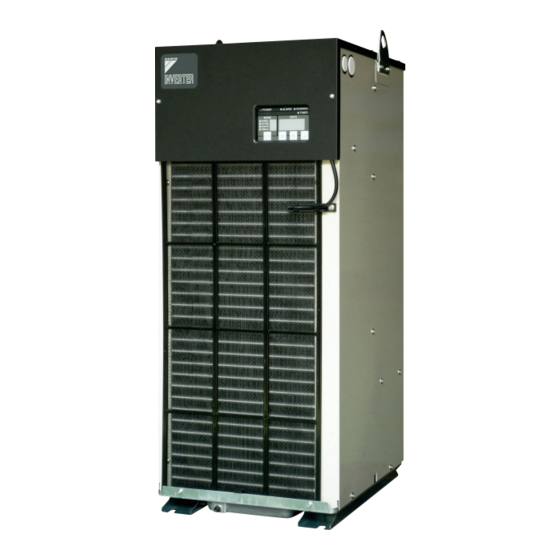
DAIKIN Oil Cooling Unit (“OILCON”). This instruction manual includes instructions for using the Oil Cooling Unit. Troubleshooting To ensure proper use of this product, be sure to read through this •...
PIM00318A_EN.fm Page 1 Tuesday, October 26, 2010 12:37 PM Safety Precautions Before using this product, read the following instructions carefully to ensure proper use. The instructions described below are intended to prevent injury or damage to you and other people. Possible conditions that may result from improper handling are classified as follows: DANGER WARNING...
Page 4
Do not modify this unit. casing or terminal covers of the motor or other Any person other than DAIKIN authorized service personnel must electric parts removed. Failure to observe this not disassemble or repair this unit. Failure to observe this instruction may result in electric shock.
Page 5
PIM00318A_EN.fm Page 3 Tuesday, October 26, 2010 12:37 PM WARNING If an abnormal condition occurs, stop operation immediately. If refrigerant leaks, provide thorough ventilation. If a large quantity of refrigerant is filled in the site, If an abnormal condition occurs, stop operation people in the site may be anesthetized or of the unit, and leave it unused until the cause of suffocated.
PIM00318A_EN.fm Page 4 Tuesday, October 26, 2010 12:37 PM Electrical Hazard You may be seriously injured or killed because of an electric shock or fire. Do not open the cover of electric component box during the operation. Maintenance and inspection should be Heat carried out by qualified personnel after the power supply is turned OFF.
PIM00318A_EN.fm Page 5 Tuesday, October 26, 2010 12:37 PM Method of Transportation / Conveyance / Storage Precautions on transportation / conveyance / storage 1. During transportation or conveyance, wear gloves and a helmet. 2. Do not transport or convey the product by any method other than that specified below. 3.
PIM00318A_EN.fm Page 6 Tuesday, October 26, 2010 12:37 PM Precautions for Installation Installation place and oil piping To install this unit, select a place that meets the following conditions: 1. Horizontal and rugged floor face (vertical interval 5 mm or less) 7.
– Condition: ISO VG32, Viscosity: 200 mm ∗1: The above pipe size may not be applied to the unit, depending on the pipe specifications. For details, contact DAIKIN. ∗2: Refer to the pipe resistance calculation formula. Pipe resistance calculation method...
PIM00318A_EN.fm Page 8 Tuesday, October 26, 2010 12:37 PM Electric Wiring Conduct electric wiring according to the local wiring standard. For the power supply, be sure to use the commercial power source. If you use the inverter power source or other power source, the product may cause burnout.
Page 11
PIM00318A_EN.fm Page 9 Tuesday, October 26, 2010 12:37 PM Mounting a circuit breaker The Oil Cooling Unit is not equipped with a circuit breaker. Be sure to mount a 3-pole circuit breaker (∗) exclusively for the Oil Cooling Unit to the main machine. For the breaker capacity, refer to the specifications of each model (see page To ensure safety, it is recommended to use an earth leakage breaker.
Page 12
PIM00318A_EN.fm Page 10 Tuesday, October 26, 2010 12:37 PM Outline of electrical equipment box (Typical) Signal terminal block Protect SW Short-circuit bar Signal terminal block Anchor mount Protect SW Short-circuit bar Customer's wiring Customer's wiring 9 10 11 13 30 31 60 61 62 64 65 66 9 10 11...
Page 13
PIM00318A_EN.fm Page 11 Tuesday, October 26, 2010 12:37 PM Connection of external output contact To output the Oil Cooling Unit operation status signal to the main machine, connect the required signal cable to the signal 39·40 terminal block according to the procedure below. For details of alarms, refer to “Alarm list” (page ).
Page 14
PIM00318A_EN.fm Page 12 Tuesday, October 26, 2010 12:37 PM Electric wiring diagram (Typical: AKZ329)
∗2: Be sure to use a commercial power supply. Using an inverter power supply may result in burnout. Voltage fluctuation range should be within ±10%. If voltage fluctuation exceeds ±10%, consult DAIKIN. ∗3: For the different-voltage model, three types (–046, –047 and –048) –047 and –048 is equipped with transformer. (–046 is without transformer.
PIM00318A_EN.fm Page 14 Tuesday, October 26, 2010 12:37 PM Before Operation Before operating the Oil Cooling Unit, check the following items: Operating environment • Check the atmosphere for any factor (dust, oil mist, high temperature, high humidity, etc.) that may adversely affect the unit. •...
PIM00318A_EN.fm Page 15 Tuesday, October 26, 2010 12:37 PM Part Names and Functions Standard (–B, –C, 046) (13) (15) (10) (11) (14) (12) –047, –048 –H –T (16) (17) (18) Name Function Name Function Sucks and compresses the low-temperature, Located at the front of the condenser. It is intended low-pressure gas refrigerant produced in the to prevent cooling capacity deterioration by Compressor...
PIM00318A_EN.fm Page 16 Tuesday, October 26, 2010 12:37 PM Names and Functions of the Control Panel Parts Outline of control panel (10) (11) (9) Name Description Reference page Power lamp (Green) Lit while power supply is ON. Indicates the control panel operation mode. NORMAL : Normal mode Operation mode indicator SETTING : Operation setting mode...
Page 19
PIM00318A_EN.fm Page 17 Tuesday, October 26, 2010 12:37 PM Operation mode The control panel provides the following seven operation modes. Among these seven modes, only four modes are available for normal operations. In other modes, the Oil Cooling Unit may malfunction depending on operation. Before using each mode, please understand the description on each mode.
Is “U1” displayed on the control panel? phases (L1, L2 and L3). Is the “Operation lock” mode selected? Cancel the operation lock mode. The DAIKIN factory setting is the “Operation lock” mode. If you keep pressing the keys ∗ The “Operation lock”...
PIM00318A_EN.fm Page 19 Tuesday, October 26, 2010 12:37 PM Operation Setting The Oil Cooling Unit operation setting provides the following modes. ∗3 Reference Operation mode ∗1 Control method Control target Setting range temperature (Reference page) Holding constant oil temperature Fixed temperature Inlet oil temperature 0 (p.
PIM00318A_EN.fm Page 20 Tuesday, October 26, 2010 12:37 PM Holding Constant Oil Temperature To hold a constant oil temperature, the following two types of operation settings are available. Operation mode: 0 Controlling the inlet oil temperature at a constant temperature Controlling the outlet (returned) oil temperature at a constant temperature...
PIM00318A_EN.fm Page 21 Tuesday, October 26, 2010 12:37 PM Tuning Oil Temperature to Room Temperature (or Machine Temperature) To tune the oil temperature to the room temperature (or machine temperature), the following four types of operation settings are available. Tuning the inlet oil temperature the room temperature Operation mode: 3...
PIM00318A_EN.fm Page 22 Tuesday, October 26, 2010 12:37 PM Cooling Oil at Constant Capacity (%) Cooling oil at a constant capacity (%) Operation mode: 9 With the above operation setting, the Oil Cooling Unit executes cooling operation according to the specified capacity command (%).
PIM00318A_EN.fm Page 23 Tuesday, October 26, 2010 12:37 PM Monitor Items When the “Monitor mode” is selected, the following items can be checked. Description Note ∗1 Machine temperature [Th1] ∗1 Outlet oil temperature or returned oil temperature [Th2] ∗1 Room temperature [Th3] ∗1 Inlet oil temperature [Th4] ∗1...
PIM00318A_EN.fm Page 24 Tuesday, October 26, 2010 12:37 PM Timer Operation With the “ON” timer, the Oil Cooling Unit can be started after elapse of a desired time. This mode can be used to warm up the main machine. The operation start time setting range is 0 to 999 hours (in one hour steps). ∗...
PIM00318A_EN.fm Page 25 Tuesday, October 26, 2010 12:37 PM Additional Setting Functions You can additionally set up the following functions by setting the parameters of the Oil Cooling Unit. Additional setting functions Auto-tuning: Automatically sets up the parameters appropriately for the system. page Temperature range warning: Activates warning output when oil temperature exceeds preset temperature range.
Page 28
PIM00318A_EN.fm Page 26 Tuesday, October 26, 2010 12:37 PM Parameter setting procedure You can set the parameter that enables the additional setting functions of the Oil Cooling Unit. For description of the additional setting functions and parameter list, refer to page Setting procedure 1.
PIM00318A_EN.fm Page 27 Tuesday, October 26, 2010 12:37 PM Setting Additional Function —“Temperature range warning” Outline of the function • As an additional function of the Oil Cooling Unit, you can set up the “Temperature range warning” function. This function allows you to specify a desired temperature range within the Oil Cooling Unit operating range. When the control temperature exceeds the preset range, the unit informs you of the “Temperature range warning”...
Page 30
PIM00318A_EN.fm Page 28 Tuesday, October 26, 2010 12:37 PM ∗ Enter Group B (page Description on parameter settings (Group A) ) before Group A, so that the temperature range warning is not activated during setup. In this section, set the following parameters by using three digits (first, second and third digits) of each parameter on the control panel data display.
Page 31
PIM00318A_EN.fm Page 29 Tuesday, October 26, 2010 12:37 PM Description on parameter settings (Group B) In this section, set the following parameters by using three digits (first and second digits, and first decimal place) of each parameter on the control panel data display. •...
PIM00318A_EN.fm Page 30 Tuesday, October 26, 2010 12:37 PM For Temperature Control Improvement —“Auto-tuning mode” ∗ To use the Oil Cooling Unit in normal conditions, this function is not required. Outline of the function Depending on the system of the main machine, problems of “unstable temperature control” or “slow response in temperature ∗...
Page 33
PIM00318A_EN.fm Page 31 Tuesday, October 26, 2010 12:37 PM Operation flow Keep pressing these keys simultaneously for five seconds. 1. Starting auto-tuning Cancel Normal mode (Original operation mode) 2. Step: 0 (Checking tuning conditions) Cancel Normal mode Cancel Error (Original operation mode) (Original operation mode) Normal 3.
Page 34
PIM00318A_EN.fm Page 32 Tuesday, October 26, 2010 12:37 PM [Note] 1. When starting auto-tuning, make sure that the oil temperature is nearly equal to the room temperature (in stable condition). Leave the main machine under no load (stopped). To complete the auto tuning correctly, start the auto tuning after the power supply to OILCON is turned ON more than 5 minutes. 2.
PIM00318A_EN.fm Page 33 Tuesday, October 26, 2010 12:37 PM Alarm/Warning Output Logic The Oil Cooling Unit can output an operation status signal to the main machine through wiring to the signal terminal block and parameter setup. 1. Connect the required signal cable to the signal terminal block. (For the connecting method, refer to “Connection of external output contact”...
27.5 control AKZ9–OP–K10 (10 m) (embedded in R1/8 Lead wire machine body) AKZ9–OP–K15 (15 m) AKZ9 series For machine Bar-type terminal plug AKZ9–OP–A5 (5 m) 1 · 25-3 temperature tuning control (attached to machine Lead wire body surface) AKZ9–OP–A10...
XHP-3 (Blue) AKZ9–OP–Y5 (5 m) For returned oil SXH-001T-0.6 temperature control 27.5 AKZ9 series (Mounted to main machine oil piping) R1/8 Lead wire AKZ9–OP–Y10 (10 m) Characteristics of thermistor: Resistance R25 (resistance at 25˚C) = 20 kΩ, Tolerance: ±3% (Temperature equivalent: ±0.4˚C)
PIM00318A_EN.fm Page 36 Tuesday, October 26, 2010 12:37 PM Optional Parts Communication with main machine When this optional board is mounted to the Oil Cooling Unit to connect this unit to the main machine: 1. You can change the operation mode and operation setting from the main machine. 2.
Packing of the electric component box • If the packing of the electric component box is seriously damaged, consult DAIKIN contact center. If you use the product without a change, the protection structure of IP54 cannot be maintained and the electric component may break down.
When the Oil Cooling Unit does not work well, first check the following points. If the problem persists, contact DAIKIN Contact Center with information on the following 1), 2) and 3) items. (For phone/fax number and address of DAIKIN Contact Center, see the back cover.) 1) Machine name (Full Model No.)
3) The air filter is clogged, or the condenser is dirty. Clean the air filter. (See “Maintenance/Inspection” on page 4) Any factor other than the above Contact DAIKIN Contact Center. 1) The oil temperature or room temperature Use the unit within the specified operating range.
Page 42
60˚C. that the refrigerant gas has leaked. Contact DAIKIN Contact Center. Identify the thermistor that indicates the error in the monitor mode on the operation panel (“-99.9” is displayed), and check the thermistor wiring.
Page 43
PIM00318A_EN.fm Page 41 Tuesday, October 26, 2010 12:37 PM When a warning is activated A warning is generated when the status of OILCON is not normal or the oil temperature to be monitored exceeds the setting temperature range. If you continue operation without a change, OILCON may break down. Be sure to take measures. Warning list Warning Description...
Need help?
Do you have a question about the AKZ9 Series and is the answer not in the manual?
Questions and answers