Advertisement
Quick Links
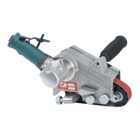
Disassembly Instructions - 0.7 hp. Dynangle Air Motor
Models: 14200
Important: Use these instructions along with the tool parts page or manual.
Notice: Shut off the air supply and depress throttle lever to deplete the remaining air.
• Carefully disconnect the tool from the air supply hose. • Remove the cover and the abrasive
belt. • Use the Special Repair Tools designed for the disassembly and assembly of this motor.
Motor Disassembly:
1/8" hex key
1/8" Hex Key
1. Use a 1/8" hex key to loosen the 95530 Screw.
Remove the motor from the belt housing.
Advertisement

Subscribe to Our Youtube Channel
Related Manuals for Dynabrade Dynangle 14200


Summary of Contents for Dynabrade Dynangle 14200
- Page 1 Disassembly Instructions - 0.7 hp. Dynangle Air Motor Models: 14200 Important: Use these instructions along with the tool parts page or manual. Notice: Shut off the air supply and depress throttle lever to deplete the remaining air. • Carefully disconnect the tool from the air supply hose. • Remove the cover and the abrasive belt.
- Page 2 19 mm Wrench 2. Use a 19 mm wrench to hold the motor spindle. By hand, or with groove pliers, grasp the drive wheel and remove it. Turn counterclockwise.
- Page 3 1-1/2" crowfoot wrench 3. Carefully fasten the 01739 Housing in a vise with aluminum or bronze jaws so that the spindle is pointing up. Use a 1-1/2" crowfoot wrench to remove the 01748 Exhaust Cover. Turn counterclockwise. Remove the 01744 Silencer.
- Page 4 Pull the motor out of the housing.
- Page 5 96346 Bearing Separator 4. Fasten the 96346 Bearing Separator (2") around the 01028 Cylinder. Place the separator and the motor in the 96232 Arbor Press (#2) so that the rotor spindle is pointing down. Use a 5/32" or 4 mm diameter flat end drive punch to push the rotor out of the 02649 Bearing.
- Page 6 96213 Bearing Removal Tool 96346 Bearing Separator 5. Use the 96213 Bearing Removal Tool and the arbor press to remove the 02649 Bearing from the rear bearing plate.
- Page 7 6. Fasten the 55025 Rotor in the vise with aluminum or bronze jaws and use an adjustable wrench to remove the 01708 Rotor Nut. Turn counterclockwise. Remove the 01007 Bearing, 01008 Bearing Plate, shims, and 01010 Spacer. Motor Disassembly Completed. Clean and inspect parts before assembling.
- Page 8 Assembly Instructions - 0.7 hp. Dynafile III Air Motors Motor Assembly: .003" (~0.80 mm) shim thickness 01010 Spacer 1. Install the 01010 Spacer onto the rotor. Install .003" (~0.80 mm) shim thickness into the 01008 Front Bearing Plate. Install the 01007 Bearing into the front bearing plate. Install the bearing and plate onto the rotor.
- Page 9 .001"-.0015" (~0.03-0.04 mm) 2. By hand, install the 01708 Rotor Nut. Pull the front bearing plate forward to take movement out of the bearing. Check the clearance between the rotor and plate. Use a .001" (~0.03 mm) thick feeler gauge. Notice: The clearance should be .001"-.0015"...
- Page 10 T to 17 N•m/~150 in. lbs. 3. Use a 19 mm crowfoot and a torque wrench to tighten the 01708 Rotor Nut. (T to 17 N•m/~150 in. lbs.)
- Page 11 4. Apply the 95842 Dynabrade Air Lube 10W/NR or equivalent to the 01185 Vanes and install them into the rotor.
- Page 12 96240 Bearing Press Tool 5. Use the RAISED OUTSIDE DIAMETER of the 96240 Bearing Press Tool and the arbor press to install the 02649 Bearing. Notice: Press the bearing all the way into the plate.
- Page 13 AIR INLET 6. Install the cylinder and rear bearing plate so that the air inlet openings line-up with each other.
- Page 14 96240 Bearing Press Tool Just Touch 7. Use the RAISED INSIDE DIAMETER of the 96240 Bearing Press Tool and the arbor press to install the bearing and plate. Important: Press the bearing and plate down until the rear bearing plate just touches the 01028 Cylinder.
- Page 15 8. Install the motor assembly.
- Page 16 T to 34 N·m/~300 in. lbs. Loctite #567 9. Carefull fasten the 01739 Housing in the vise with aluminum or bronze jaws so that the rotor spindle is pointing up. Notice: Over tightening vise will damage housing. Install the 15322 Felt Silencer around the 15314 Air Control Ring and install these into the 15315 Exhaust Cover.
- Page 17 Use a 3/16" hex key, and pliers to tighten drive wheel. 10. Use a 19 mm wrench to hold the motor spindle. By hand, or with groove pliers, grasp the drive wheel and install it. Turn clockwise. IMPORTANT: Use a tachometer to check motor speed and to verify proper operation.
- Page 18 1/8" Hex Key 11. Install the air motor into the belt housing. Use a 1/8" hex key to tighten the 95530 Screw and fasten the motor into the belt housing. Motor Assembly Completed. Notice: For belt housing, contact arms and valve assemblies, refer to the exploded view and additional instructions contained in the tool parts page or manual.
Need help?
Do you have a question about the Dynangle 14200 and is the answer not in the manual?
Questions and answers