Table of Contents
Advertisement
Diaphragm Vacuum Pumps and Compressors
N 035 ANE
N 035 AN.9 E
N 035 ATE
N 035 AVE
N 035 AV.9 E
N 035 SNE
N 035 STE
N 035 ST.9 E
N 035 SVE
Operating and
installation
instructions
Read and observe these
operating and installation
instructions!
KNF Neuberger GmbH
Alter Weg 3
D-79112 Freiburg
Germany
Phone +49-(0)7664 / 5909-0
Fax +49-(0)7664 / 5909-99
E-mail: info@knf.de
www.knf.de
KNF N 035 E e 08/09
Translation of the original Operating and installation instructions
N 035.1 ANE
N 035.1 AN.9 E
N 035.1 ATE
N 035.1 AT.9 E
N 035.1 AVE
N 035.2 ANE
N 035.2 AN.9 E
N 035.2 ATE
N 035.2 AVE
N 035.3 ANE
N 035.3 ATE
N 035.3 AVE
Contents
1. About this document................................................................. 2
2. Use ........................................................................................... 3
3. Safety ....................................................................................... 4
4. Technical Data ......................................................................... 5
5. Design and Function ................................................................ 9
6. Installation and connection..................................................... 12
7. Operation................................................................................ 19
8. Servicing................................................................................. 21
9. Troubleshooting...................................................................... 28
10. Spare parts and accessories.................................................. 30
11. Decontamination Declaration ................................................. 32
Valid from : Aug. 2009
N 035.1 SNE
N 035.1 STE
N 035.1 SVE
N 035.2 SNE
N 035.2 STE
N 035.2 SVE
N 035.3 SNE
N 035.3 STE
N 035.3 SVE
Keep for future use!
Page
Advertisement
Table of Contents

Related Manuals for KNF N 035 ANE


Summary of Contents for KNF N 035 ANE
-
Page 1: Table Of Contents
8. Servicing................. 21 Fax +49-(0)7664 / 5909-99 9. Troubleshooting..............28 E-mail: info@knf.de 10. Spare parts and accessories..........30 www.knf.de 11. Decontamination Declaration ..........32 KNF N 035 E e 08/09 Translation of the original Operating and installation instructions Keep for future use! -
Page 2: About This Document
An activity to be carried out (a step) is specified here. 1. The first step of an activity to be carried out is specified here. Additional, consecutively numbered steps follow. This symbol refers to important information. KNF N 035 E e 08/09 Translation of the original Operating and installation instructions... -
Page 3: Use
The pumps may not be operated in an explosive atmosphere. The pumps are not suitable for transferring dusts. The pumps are not suitable for transferring liquids. KNF N 035 E e 08/09 Translation of the original Operating and installation instructions... -
Page 4: Safety
Customer service and Only have repairs to the pump carried out by the KNF Customer repairs Service responsible. Use only genuine parts from KNF for servicing work. KNF N 035 E e 08/09 Translation of the original Operating and installation instructions... -
Page 5: Technical Data
N 035.3 STE N 035 SVE N 035.1 SVE Stainless Steel N 035.2 SVE N 035.3 SVE Tab. 3 *according to DIN ISO 1629 und 1043.1 KNF N 035 E e 08/09 Translation of the original Operating and installation instructions... - Page 6 N 035.1 ATE IP 44 3 phase N 035.1 STE IP 20 N 035.1 STE IP 44 Tab. 4 (part 1) *Liters in standard state (1,013 mbar) KNF N 035 E e 08/09 Translation of the original Operating and installation instructions...
- Page 7 N 035.3 SVE IP 44 3 phase N 035.3 ATE IP 44 N 035.3 STE IP 44 Tab. 4 (part 2) *Liters in standard state (1,013 mbar) KNF N 035 E e 08/09 Translation of the original Operating and installation instructions...
- Page 8 After opening pump head or replacing the diaphragm and reed valves (or valve plate) the gas tightness is no longer guaranteed. A leak test is able to verify that the original standard of gas-tightness has been achieved. KNF N 035 E e 08/09 Translation of the original Operating and installation instructions...
-
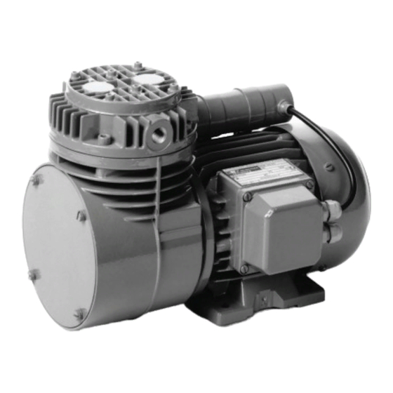
Page 9: Design And Function
Fig. 1: Diaphragm Pump N 035 ANE (IP20) Design N 035 A__E (IP44) Pneumatic pump outlet Pneumatic pump inlet Terminal box (electrical connetion) Motor Fig. 2: Diaphragm Pump N 035 ANE (IP44) KNF N 035 E e 08/09 Translation of the original Operating and installation instructions... - Page 10 Diaphragm Pump N 035 E Design and Function Fig. 3: Pneumatic connection of two-headed pumps KNF N 035 E e 08/09 Translation of the original Operating and installation instructions...
- Page 11 (1). The transfer chamber (3) is hermetically separated from the pump drive (7) by the diaphragm. KNF N 035 E e 08/09 Translation of the original Operating and installation instructions...
-
Page 12: Installation And Connection
(All dimensional tolerances conform to DIN ISO 2768-1, Tolerance Class V) Fig. 6: Mounting dimensions N 035 A_E (IP44) including .9 versions (All dimensional tolerances conform to DIN ISO 2768-1, Tolerance Class V) KNF N 035 E e 08/09 Translation of the original Operating and installation instructions... - Page 13 Fig. 9: Mounting dimensions N 035.1 A_E (IP20) and N 035.3 A_E (IP20) including .9 versions (All dimensional tolerances conform to DIN ISO 2768-1, Tolerance Class V) KNF N 035 E e 08/09 Translation of the original Operating and installation instructions...
- Page 14 (All dimensional tolerances conform to DIN ISO 2768-1, Tolerance Class V) Fig. 12: Mounting dimensions N 035.2 A_E (IP44) including .9 versions (All dimensional tolerances conform to DIN ISO 2768-1, Tolerance Class V) KNF N 035 E e 08/09 Translation of the original Operating and installation instructions...
- Page 15 Tolerance Class V) Fig. 15: Mounting dimensions N 035.2 S_E (IP20) (illustration without pneumatic connection; all dimensional toler- ances conform to DIN ISO 2768-1,Tolerance Class V) KNF N 035 E e 08/09 Translation of the original Operating and installation instructions...
- Page 16 KNF recommends that a fuse is installed in the motor supply circuit (overcurrent release). For operating current see type plate or data sheet. KNF N 035 E e 08/09 Translation of the original Operating and installation instructions...
- Page 17 5. Connect the earth (ground) wire to the motor. 6. For IP 44 versions: close the terminal cover box. Fig. 17: Y-Connection (high voltage) Fig. 18: ∆-Connection (low voltage) KNF N 035 E e 08/09 Translation of the original Operating and installation instructions...
- Page 18 3. Connect the suction line and pressure line (thread size G ¼) 4. Lay the suction and pressure line at a downward angle to prevent condensate from running into the pump. KNF N 035 E e 08/09 Translation of the original Operating and installation instructions...
-
Page 19: Operation
When the operation of the pump is interrupted by the thermal switch, the pump will restart automati- WARNING cally after cooling down. Take all necessary care to prevent this leading to a dangerous situation. KNF N 035 E e 08/09 Translation of the original Operating and installation instructions... - Page 20 (see section 8.2.1). Open pressure and suction lines to normal atmospheric pres- sure. KNF N 035 E e 08/09 Translation of the original Operating and installation instructions...
-
Page 21: Servicing
Only use solvents for cleaning if the head materials cannot be attacked (check the resistance of the material!). If compressed air is available, blow out the components. KNF N 035 E e 08/09 Translation of the original Operating and installation instructions... - Page 22 Information on procedure With multi-head pumps, parts of the individual pump heads can be confused. Replace the diaphragm and reed valves of the individual pump heads consecutively. KNF N 035 E e 08/09 Translation of the original Operating and installation instructions...
- Page 23 5. For pumps N 035_ _.9 E: To undo the retainer plate E use the wrench for retainer plate to turn it anti-clockwise; remove re- tainer plate and diaphragm F. KNF N 035 E e 08/09 Translation of the original Operating and installation instructions...
- Page 24 Carry out steps 2 to 13 for the second pump head. 15. For two-headed pumps: Reattach the tube of pneumatic head connection onto the hose connector and tighten the union nut. KNF N 035 E e 08/09 Translation of the original Operating and installation instructions...
- Page 25 WARNING Wear protective clothing if necessary, e.g. protective gloves. Flush pump before replacing the diaphragm and the valve plate (see section 8.2.1). KNF N 035 E e 08/09 Translation of the original Operating and installation instructions...
- Page 26 9. For all pumps except .9 versions: Place the ratainer plate E on the diaphragm F and tighten the new countersunk screw D (torque: 5.0 Nm). KNF N 035 E e 08/09 Translation of the original Operating and installation instructions...
- Page 27 Pull the pneumatic head connection hose back onto the hose connector. 17. For pump type N 035.2 S_E: Retighten the hose clip on the pneumatic head connection. KNF N 035 E e 08/09 Translation of the original Operating and installation instructions...
-
Page 28: Troubleshooting
Head parts are soiled. Clean head components. Diaphragm or reed valves Replace diaphragm and reed valves (valve plate), (valve plate) are worn. (see Section 8.3). Tab. 13 KNF N 035 E e 08/09 Translation of the original Operating and installation instructions... - Page 29 3. Clean the pump (see Section 8.2.2). 4. Send the pump to KNF with a filled out decontamination decla- ration (see chapter 11) and specification of the medium trans- ferred. KNF N 035 E e 08/09 Translation of the original Operating and installation instructions...
-
Page 30: Spare Parts And Accessories
N 035 SVE, N 035.1 SVE, N 035.2 SVE, N 035.3 SVE Spare part Position* Order No. Diaphragm 001405 Countersunk screw** 110711 Valve plate 001404 Tab. 18 * According to Fig. 20 ** Not for .9 versions KNF N 035 E e 08/09 Translation of the original Operating and installation instructions... - Page 31 Hose connector G1/4 000362 for tube ID 9 Hose connector stainless steel 020234 G1/4 for tube ID 9 Wrench for retainer plate .9 versions 018812 Tab. 20 KNF N 035 E e 08/09 Translation of the original Operating and installation instructions...
-
Page 32: 11. Decontamination Declaration
Pump model Serial No. Fed media The pump contains neither aggressive, biological, radioactive, poisonous nor other dangerous media. Company Date/Signature KNF N 035 E e 08/09 Translation of the original Operating and installation instructions...
Need help?
Do you have a question about the N 035 ANE and is the answer not in the manual?
Questions and answers