Table of Contents
Advertisement
Quick Links
Installation Instructions for SymCom's
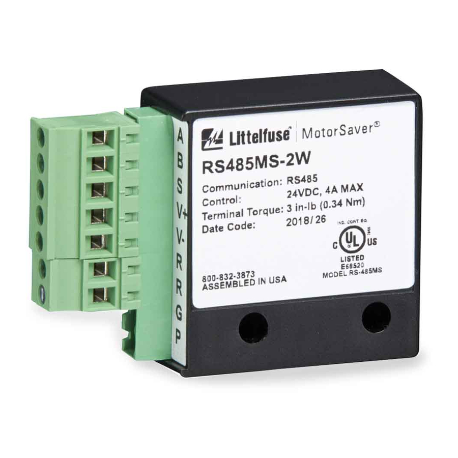
Model RS485MS-2W Communications Module
MODULE FUNCTIONS
The Model RS485MS-2W Communications Module serves two very important functions.
From a communication network view, its primary purpose is to electrically isolate the
communications network from the high voltages present in SymCom's units and to convert
the communications signals from the microprocessor's 5-volt levels into RS-485 levels. The
second function of the RS485MS-2W is to provide power to the RM-1000 remote monitor.
SymCom's units are connected to high AC voltages with a fl oating ground circuit. As long
as there are three balanced line voltages present, the resulting ground level will often be near
case ground. However, if one phase is lost or if the line voltages become unbalanced, the
fl oating ground may be as much as 480 volts above the case ground. The RS485MS-2W has
two high speed optical isolation chips on the receive and transmit pins and a low speed opto-
isolator on the transmit/receive pin to isolate the communication network from the AC line
voltages.
The signals from the microprocessor go through resistors to provide current limiting before
connecting to the 9-pin external connector. Therefore, the 9-pin SUB D connector on the
SymCom unit provides un-isolated CMOS signals and is NOT RS232 or TTL compatible.
The RS485MS-2W does not have support for four wire communications systems.
Note: Do not plug a modem or any other PC compatible device directly
RS-485 NETWORKING
To utilize SymCom's RS-485 network, three key components are required:
1.
Modbus Slave Device – SymCom model series 601, 77C, or 777 with the Model
RS485MS-2W
RS485MS-2W communications module
RS485MS-2W communications module
2.
18 to 24 AWG shielded twisted-pair cable – The twisting of the wires helps
minimize the effect of noise on the data signal.
3.
Modbus Master Device –
Modbus Master Device – RM-1000, RM-2000, PLC, or computer. On a PC,
Modbus Master Device – RM-1000, RM-2000, PLC, or computer. On a PC,
PC compatible device, and a PLC without an RS-485 port an RS-232 to RS-485
converter is required.
into the 9-pin SUB D connector on SymCom's units.
.
2880 North Plaza Drive, Rapid City, SD 57702
(800) 843-8848•(605) 348-5580•www.symcominc.com
Advertisement
Table of Contents

Related Manuals for SymCom RS485MS-2W


Summary of Contents for SymCom RS485MS-2W
- Page 1 However, if one phase is lost or if the line voltages become unbalanced, the fl oating ground may be as much as 480 volts above the case ground. The RS485MS-2W has two high speed optical isolation chips on the receive and transmit pins and a low speed opto- isolator on the transmit/receive pin to isolate the communication network from the AC line voltages.
- Page 2 120-ohm terminating resistors, external power will be required (see Appendix, Figure 3). When connecting more than one SymCom unit on an RS-485 network, only one unit is connected to the RS-232 to RS-485 converter with A to RD(B) and B to RD(A).
- Page 3 Appendix, Figure 2 does not apply, try switching the polarity of the wires. In other words, switch the connections at the A and B terminals of the RS485MS-2W module. If possible, send a START or STOP command from the Modbus Master device to the Model 777, since the START and STOP commands will be executed whether or not the Model 777 returns an acknowledgment.
- Page 4 These Model 777’s have the option “11” code in the part number. If you have a Model 777 that is not Modbus, it can be re-chipped for a nominal fee. Please contact SymCom, Inc. at the number at the end of this section for more information.
- Page 5 Figure 2: Basic Wiring Diagram Figure 2: Basic Wiring Diagram...
- Page 6 Figure 3: Basic Extended Network Diagram Figure 3: Basic Extended Network Diagram...
- Page 7 Figure 4: Basic RM-2000 Network Figure 4: Basic RM-2000 Network...
- Page 8 Figure 5: Basic RM1000 Network Figure 5: Basic RM1000 Network...
Need help?
Do you have a question about the RS485MS-2W and is the answer not in the manual?
Questions and answers