Table of Contents
Advertisement
Quick Links
OPERATION MANUAL
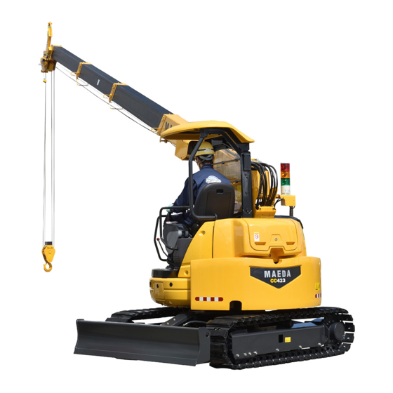
CRAWLER CRANE
CC423S
Serial No. 21001 and up
Unsafe use of this machine may cause serious injury or death. Operators
must read this manual before operating this machine. This manual should be
kept near the machine for reference and periodically reviewed by all
personnel who will come into contact with it.
MAEDA has Operation Manual written in some other languages. If a foreign
language manual is necessary, contact your local distributor for availability.
NOTICE
542E-OM1803-00
- 1
Advertisement
Chapters
Table of Contents

Related Manuals for Maeda CC423S-1


Summary of Contents for Maeda CC423S-1
- Page 1 NOTICE MAEDA has Operation Manual written in some other languages. If a foreign language manual is necessary, contact your local distributor for availability.
-
Page 3: Table Of Contents
CONTENTS Item Page INTRODUCTION 1. INTRODUCTION 2. FOR SAFE USE OF THE MACHINE 3. MACHINE OVERVIEW 3.1 SPECIFIED OPERATIONS 3.2 MACHINE STRUCTURE 3.3 MACHINE FUNCTIONS 4. QUALIFICATIONS FOR OPERATION 4.1 QUALIFICATIONS FOR CRANE OPERATION 5. TERMINOLOGY 5.1 TERMS AND DEFINITIONS 5.2 DIAGRAM OF WORKING RADIUS AND LIFTING HEIGHT 5.3 RATED TOTAL LOAD CHART 6. -
Page 4: Item Page
Item Page OPERATION 1. NAME OF EACH SECTION 1.1 MACHINE UNITS 1.2 CRANE OPERATION UNITS 2. EXPLANATION OF EACH EQUIPMENT 2.1 MACHINE MONITOR 2.1.1 MONITOR BASIC ACTION AND DISPLAY 2.1.2 WARNING DISPLAY 2.2 SWITCHES 2.3 MOMENT LIMITER (OVERLOAD DETECTOR) 2.3.1 CONFIGURATION OF MOMENT LIMITER 2.3.2 FUNCTIONS OF MOMENT LIMITER 2.3.3 MOMENT LIMITER OPERATION AND CANCELLING (RECOVERY) 2.3.4 MOMENT LIMITER FUNCTIONS... - Page 5 Item Page 3.13 HOISTING AND LOWERING 3.13.1 NORMAL HOISTING AND LOWERING 3.13.2 HOISTING OPERATION WITH HOOK STOWAGE SWITCH 3.14 BOOM DERRICKING OPERATION 3.15 BOOM TELESCOPING OPERATION 3.16 SLEWING OPERATION 3.17 CRANE STOWAGE OPERATION 3.17.1 CRANE STOWAGE OPERATION AT THE TIME OF SIMPLE STOWAGE OF HOOK BLOCK 3.17.2 CRANE STOWAGE OPERATION AT THE TIME OF NORMAL STOWAGE OF HOOK BLOCK...
- Page 6 Item Page 8. TROUBLESHOOTING 8.1 WHEN FUEL RUNS OUT 8.2 PHENOMENON WHICH IS NOT A FAULT 8.3 WHEN BATTERY HAS DISCHARGED 8.3.1 BATTERY HANDLING PRECAUTIONS 8.3.2 REMOVING/INSTALLING BATTERY 8.3.3 CAUTIONS IN CHARGING BATTERY 8.3.4 STARTING ENGINE WITH BOOSTER CABLE 8.3.5 STARTING ENGINE 8.4 WHEN THESE PHENOMENA HAPPEN 8.4.1 ELECTRICAL COMPONENTS 8.4.2 MACHINE BODY...
- Page 7 Item Page SPECIFICATIONS 1. PRINCIPAL SPECIFICATIONS LIST 2. SPECIFICATION DIMENSIONAL DRAWING 3. RATED TOTAL LOAD CHART 4. WORKING RADIUS/LIFTING HEIGHT SEARCHER HOOK (OPTION) 1. SAFETY PRECAUTIONS 1.1 MOMENT LIMITER SETTINGS 1.2 SAFETY LABEL LOCATIONS 2. NAMES OF SEARCHER HOOK PARTS 3.
- Page 8 This Page Intentionally Left Blank.
-
Page 9: Introduction
INTRODUCTION 1. INTRODUCTION 2. FOR SAFE USE OF THE MACHINE 3. MACHINE OVERVIEW 4. QUALIFICATIONS FOR OPERATION 5. TERMINOLOGY 6. NECESSARY INFORMATION FOR SERVICING... -
Page 10: Introduction
• Avoid operating this machine before understanding this manual thoroughly. • Keep this manual at hand so that you can read it when necessary. • If you lose or damage this manual, contact Maeda or our sales service agency immediately to order a new one. -
Page 11: For Safe Use Of The Machine
2. FOR SAFE USE OF THE MACHINE This manual classifies the risks into the following three categories for easy understanding of the safety information. This denotes that there is an imminent hazard which will cause serious injury or death. It also provides information on how to avoid such hazard. This denotes that there is a hazard which can cause serious injury or death. -
Page 12: Machine Overview
3. MACHINE OVERVIEW 3.1 SPECIFIED OPERATIONS This machine is to be used for the following operation(s): • Crane operation • Travelling hoist operation This machine is a mobile crane consisting of the upper swiveling body equipped with a boom type crane and the lower crawler type carrier. This self-propelled crane is capable of moving (travelling) in the work site and craning an object weighing up to the rated total load. -
Page 13: Machine Functions
This machine is composed of the following units and systems: CARRIER Consists of the travelling system. UPPER SLEWING BODY (CRANE) Consists of the engine, travelling operation unit, crane operation unit, boom telescoping unit, boom derricking unit, slewing unit, hook block and winch system. SAFETY DEVICE Comprises the over-hoisting prevention device, over-lowering prevention device, overload preventive device, slinging rope detachment protector, hydraulic safety valve, telescoping... -
Page 14: Qualifications For Operation
4. QUALIFICATION FOR OPERATION • A high incidence of occupational accidents in crane operation has been reported. Be aware that experienced engineers are also no exception. • Warnings and precautions defined in this manual shall be observed for safety assurance during operation of the machine. -
Page 15: Terminology
5. TERMINOLOGY 5.1 TERMS AND DEFINITIONS RATED TOTAL LOAD The maximum load that can be applied according to the boom length and angle. The load includes the mass (weight) of hoisting accessories (hooks) and slinging ropes. RATED LOAD A load derived by subtracting the mass (weight) of hoisting accessories (hooks) and slinging ropes from the rated total load, and can be hoisted. -
Page 16: Diagram Of Working Radius And Lifting Height
5.2 DIAGRAM OF WORKING RADIUS AND LIFTING HEIGHT • The working radius/lifting height shows relationship between working radius, boom angle and lifting height above ground of this machine with no load hoisted, and deflection of the boom is not included. •... -
Page 17: Rated Total Load Chart
Working Radius. • The rated total load chart indicates the load including the mass of hoisting accessories (hook mass: 30 kg). CC423S-1 RATED TOTAL LOAD CHART (3) 6.87 m (4) 8.71 m (1) 3.18 m boom (2) 5.03 m boom... - Page 18 The rated total load chart provides the maximum loads that the crane is capable of hoisting depending on boom length, for each working radius. Boom length The headings in the rated total load chart, “3.18 m boom (1)”, “5.03 m boom (2)”, “6.87 m boom (3)”...
- Page 19 4. “8.71 m boom (4)”: All the booms are fully extended. If more than half of the “ mark” of boom (3) is exposed from boom (2), work should be performed in accordance with the values of this column.
-
Page 20: Necessary Information For Servicing
6. NECESSARY INFORMATION FOR SERVICING When arranging servicing of the machine, or when ordering parts, please contact the Company or our sales service agency with the following information. Machine ID plate This is located on the lower right part of the canopy. Engine No. - Page 21 EPA ID plate and location This is located on the upper surface of the engine. EPA: Environmental Protection Agency (US Environmental Protection Agency) Hour meter location This is displayed on the machine monitor.
- Page 22 This Page Intentionally Left Blank.
-
Page 23: Safety
SAFETY 1. BASIC PRECAUTIONS 2. OPERATION RELATED PRECAUTIONS 3. TRANSPORT PRECAUTIONS 4. TOWING PRECAUTIONS 5. MAINTENANCE PRECAUTIONS 6. SAFETY LABEL LOCATIONS All the safety precautions defined in this manual should always be read and observed. Failure to follow the safety precautions can cause serious personal injury or death. -
Page 24: Basic Precautions
1. BASIC PRECAUTIONS Incorrect operation and servicing may result in serious bodily accidents. Before starting operation and servicing, read this manual and safety labels to observe their warnings and precautions. 1.1 PRECAUTIONS BEFORE STARTING WORK OBSERVE THE MANUAL AND SAFETY LABELS •... -
Page 25: Preparing For Safe Operation
1.2 PREPARING FOR SAFE OPERATION PROVIDE SAFETY DEVICES FOR SURE • Check that all guards, covers and mirrors are attached properly. Repair immediately if damaged. • Understand how to use the safety devices well and use properly. • Do not detach the safety devices under any circumstances. Keep control to achieve proper function all the time. - Page 26 USE OF MACHINE THAT WAS RENTED OR PREVIOUSLY USED BY SOMEONE ELSE Check the following subjects in writing before using any machine that was rented or previously used by someone else. In addition, check the inspection record table for the maintenance conditions such as the periodic inspections.
-
Page 27: Precautions For Fire Prevention
1.3 PRECAUTIONS FOR FIRE PREVENTION WHAT TO DO IF A FIRE OCCURS • Turn the starter switch OFF to stop the engine. • Get out of the machine by using a handrail and steps. • Do not jump off the machine. You may fall and get hurt. PREVENTING FIRE •... -
Page 28: Cautions In Getting On And Off The Machine
1.4 CAUTIONS IN GETTING ON AND OFF THE MACHINE USE A HANDRAIL AND STEPS WHEN GETTING ON AN OFF THE MACHINE When getting on and off the machine, be sure to observe the following precautions in order to prevent physical accidents such as slipping and falling or tumbling. -
Page 29: Other Precautions
1.5 OTHER PRECAUTIONS CAUTION AGAINST BEING CAUGHT In the periphery of the upper slewing body and crane unit, the clearance varies with the motion of derricking cylinder and winch. If being caught in it, serious injury may occur. Keep persons away from all rotating and telescoping sections. Never allow your body or part of it to get in the following gaps: •... -
Page 30: Operation Related Precautions
2. OPERATION RELATED PRECAUTIONS 2.1 PRECAUTIONS ON WORK SITE SURVEY AND SAFETY ASSURANCE OF WORK SITE A number of risks that may cause serious injury are imbedded in a work site. Before starting work, check the following matters beforehand to ensure that no danger is present at the work site: •... - Page 31 BEWARE OF ELECTRICAL CABLE ABOVE • Do not let the machine touch the electrical cables above. High voltage cables may also inflict electrical shock by close proximity. • Slinging operators are likely to suffer electrical shocks. Always observe the following to prevent accidents. •...
- Page 32 CAUTIONS WHEN OPERATING CRANE IN LOCATION WITH HIGH OUTPUT MICROWAVE EMISSION Operating the crane near high output microwave emission equipment such as a radar or TV/radio broadcast antenna causes the crane construction to be exposed to the microwave and generates induced current, therefore is very dangerous.
-
Page 33: Cautions When Starting Engine
2.2 CAUTIONS WHEN STARTING ENGINE PAY ATTENTION TO WARNING SIGNS When warning sign “DANGER. Do NOT operate” is put up, the machine is being inspected and under maintenance. Do not start the engine and refrain from touching operating levers. Disregarding the warning sign to operate the machine may give rise to the danger of involving the maintenance personnel into the rotating parts or movable parts of the machine, resulting in serious injury. - Page 34 CAUTIONS UNDER COLD WEATHER • Defrost and remove snow from the slewing gear, boom and winch. Check their movements before starting work. • Operating the machine without sufficient engine warm-up causes slow response of the machine to the operation of levers and pedals, and thus unexpected motion may occur against the operator’s will.
-
Page 35: Precautions For Starting Carrier And Operating Crane
2.3 PRECAUTIONS FOR STARTING CARRIER AND OPERATING CRANE INSPECTION BEFORE STARTING OPERATION Omitting the inspections after starting the engine results in delay to discover the machine abnormalities, and may result in accidents and machine damages. Inspection should be carried out in a clear area. No unauthorized persons should be able to approach the machine. - Page 36 CAUTIONS WHEN TRAVELLING Always observe the following to prevent serious injuries and accidental death when moving the machine. • Set the machine to the travelling posture in the right figure. Refer to the preceding subsection “CAUTIONS ON MACHINE FORWARDING/REVERSING AND SLEWING”. •...
- Page 37 BE CAREFUL OF TRIPPING ON UNSTABLE GROUND Always observe the following to prevent serious injuries and death accidents when travelling over an unstable ground for unavoidable reasons. • Do not enter soft ground area. The machine may get stuck. • The ground near cliff, roadside and deep gully is unstable, so avoid going near such ground as much as possible.
-
Page 38: Cautions During Crane Operation
2.4 CAUTIONS DURING CRANE OPERATION INSPECTION BEFORE STARTING WORK Check that the safety devices and crane operate properly. • Operate each of the operation levers, pedals and switches under no load, and check that operations take place without any abnormality. Repair immediately if any abnormality exists. - Page 39 CAUTIONS WHEN WORKING ON A SLOPE When inevitably perform operation on a slope, provide an earth fill (B) to create a horizontal, solid and strong footing for installing the machine in order to prevent it from tumbling. Attempting a diagonal hoisting without ensuring the horizontal installation of the machine not only disturbs the normal functioning of the moment limiter (overload prevention device), but also affect the machine with an unexpected force, resulting in tumbling or...
- Page 40 PAY ATTENTION TO WEATHER INFORMATION • A risk of lightning exists in case of a thunderstorm, so abort operating the crane, immediately lower the load and retract the boom. • Wind can cause the hoisted load to move back and forth, which could cause the machine to become unstable.
- Page 41 CAUTIONS WHEN SLINGING • Check the following before hoisting a load. Attempt to hoist the load without checking may result in serious accidents by dropping the load or tripping. • Observe the values in the rated total load chart. • Hoist from the centre of gravity of the load. •...
- Page 42 CAUTIONS WHEN OPERATING CRANE • Stability of a crane is decisively critical in the transverse direction of the carrier. In the diagonal direction, although stability is increased, exceeding the rated load may result in damage of the boom or machine body. Do not turn the moment limiter (overload prevention device) off, even if operating in the diagonal direction.
- Page 43 CAUTIONS ABOUT HIGH TEMPERATURE OIL WHEN OPERATING CRANE When hydraulic oil temperature exceeds 80 °C, high pressure hoses and seals can be damaged by heat, and it may cause burning to skin from oil spray. If temperature of hydraulic oil exceeds 80 °C, stop the operation and wait until the oil cools down. Hook raising/lowering operation at high lift or continuous crane operation with the accelerator pedal depressed will increase the hydraulic oil temperature.
- Page 44 CAUTIONS WHEN OPERATING BOOM • Perform boom operation lever operation as slowly as possible. Especially avoid sudden lever operations when the load is hoisted, which may cause the load to waggle and give large impact to the machine, and thus may damage the crane or trip the machine.
- Page 45 CAUTIONS FOR WORK AT WORKPLACE WHERE LIFT BELOW GROUND LEVEL IS PERFORMED • When lowering a wire rope for work underground, leave at least 3 turns of wire rope on the winch drum. • Make sure to give signals. • Perform crane operation with extra care. CAUTIONS ON TRAVELING WITH HOISTED LOAD Hoisted load travelling operation is in principle forbidden, because it is extremely unstable and dangerous.
-
Page 46: Transport Precautions
3. TRANSPORT PRECAUTIONS CAUTIONS DURING TRANSPORT When transporting the machine, there is a risk of inviting a serious bodily accident incurred by an accident during transportation. • Strictly observe the following when transporting the machine. • Depending on the type of crane installed, the mass, height and total length of the machine are varied, and thus check these details. -
Page 47: Towing Precautions
4. TOWING PRECAUTIONS TOWING PRECAUTIONS When towing, errors in the choice of wire rope, inspection methods, towing methods etc. may result in serious injury or death. • Be sure to check that the wire rope for towing and the towing rod have sufficient strength for the weight of the machine being towed. -
Page 48: Maintenance Precautions
5. MAINTENANCE PRECAUTIONS 5.1 PRECAUTIONS BEFORE MAINTENANCE PUT UP A WARING SIGNBOARD DURING INSPECTION/MAINTENANCE • When the warning sign, “DANGER. Do NOT operate”, is in place, the machine is being inspected or under maintenance. Do not start the engine and refrain from touching operating levers. Disregarding the warning sign to operate the machine may give rise to the danger of involving the maintenance personnel into the rotating parts or movable parts of the machine, resulting in serious... - Page 49 KEEP ENGINE STANDING STILL DURING INSPECTION AND MAINTENANCE • Before starting inspection and maintenance servicing, be sure to retract the crane and stop the engine. • Turn the starter switch to the “OFF” position and set the lock lever (1) to the “Lock” position (L). •...
- Page 50 USE APPROPRIATE TOOLS Use proper tools and handle them in correct manners. Using a damaged or deformed tool and using it for any purpose other than its intended application may giving rise to a serious bodily accident. PRECAUTIONS FOR WORKING AT HIGH ELEVATION Secure scaffolding by using a workbench with the stairs when working at high elevation.
-
Page 51: Precautions During Maintenance
5.2 PRECAUTIONS DURING MAINTENANCE CAUTIONS DURING WELDING REPAIR Conduct welding operation in a location with good facility, and, only authorized personnel are permitted to be engaged in the welding work. Unauthorized personnel are strictly prohibited since risks such as gas generation, fire and electrical shock are present when welding. - Page 52 BEWARE OF CHIPS WHEN WORKING WITH HAMMER Working with a hammer may cause a serious bodily accident because of springing off of a pin or littering of metallic chips. Strictly observe the following. • Hitting a pin or the like may give rise to shattering of broken chips to hurt people nearby.
- Page 53 BEWARE OF FUEL UNDER HIGH INTERNAL PRESSURE In the engine fuel piping, an internal pressure is generated during engine operation. Before starting the inspection and maintenance servicing of fuel piping, wait until its internal pressure is relieved. After stopping the engine, wait for 30 seconds or more before starting the work. HANDLING HIGH PRESSURE HOSE AND PIPING If fuel leaks from a hose or piping, there occurs a risk of fire and malfunction leading to a serious bodily accident.
- Page 54 NEVER DISASSEMBLE THE RECOIL SPRING Under no circumstances, refrain from disassembling the recoil spring assembly. In the recoil spring assembly that is intended for buffering the idler, a strong spring is installed. An inadvertent disassembling it causes the spring to jump out, inviting a serious bodily accident. Contact us or our sales service agency if its disassembling is required.
-
Page 55: Safety Label Locations
6. SAFETY LABEL LOCATIONS Keep safety labels clean and visible at all times. If lost, replace immediately or apply for a new one. There are other labels than safety labels shown below and treat them in the same manner. SAFETY LABEL LOCATIONS (1/2) - Page 56 SAFETY LABEL LOCATIONS (2/2)
- Page 57 (4) Fuel Caution (CL000280200) (5) Hydraulic Oil Injection Port Warning (542-4782600) (6) Trapping Risk / No Entry When Slewing (7) Belt Entanglement Caution (CL000080010) (CL000180012) (8) Do Not Step On (584-4581700) (2 places) (9) Plug Ejection Caution (CL000190010) (2 places) (11) Hoisting Position Warning (584-3437800)
- Page 58 (12) Burn Injury Caution (CL000170005) (15) Hook Block Winding Caution (553-4267400) (2 places) (16) Winch Winding Caution (553-4267500) (23) Caution for lifting machine (541-3472400) (21) Warning (541-4614900)
- Page 59 (24) Machine Mass (542-4773100) (28) Working Radius / Rated Total Load Chart (542-3582200)
- Page 60 (30) Safe Operation (557-3494500) (31) Operating the Moment Limiter (542-2250000)
- Page 61 (32) Lever Operating Patterns (556-3368100) (34) Cautions on override switch (35) Number of Falls Switching Warning (585-3555500) (585-4739200) (36) Warnings on Operation, Inspection and Maintenance (584-3469700)
- Page 62 (38) Washing Caution (300-4213900) (3 places) (39) Driving Prohibited Tag (585-4738300) (47) Trapping Risk (553-4267600) (48) Boom Operation Caution (542-4774400) (2 places) (49) High-Pressure Washing Around Operator’s Seat (50) High-Pressure Washing Within Cover Prohibited Prohibited (542-4774900) (CL000240110) (52) Warning for blade operation (556-4575300)
-
Page 63: Operation
OPERATION 1. NAME OF EACH SECTION 2. EXPLANATION OF EACH EQUIPMENT 3. OPERATION 4. HANDLING WIRE ROPE 5. TRANSPORTATION 6. HANDLING MACHINE IN COLD ENVIRONMENT 7. LONG-TERM STORAGE 8. TROUBLESHOOTING... -
Page 64: Name Of Each Section
1. NAME OF EACH SECTION 1.1 MACHINE UNITS (1) Hook Sprocket (2) Hook block Track frame (3) Wire rope (10) Idler (4) Boom (11) Tri-colour revolving working status lamp (5) Derricking cylinder (12) Override switch (6) Winch (13) Working lamp (7) Crawler (14) Headlight... -
Page 65: Crane Operation Units
1.2 CRANE OPERATION UNITS (1) Operator’s seat (10) Levelling instrument (2) Light switch (11) Starter switch (3) Lock lever (12) Speed-up pedal (4) Left work equipment operation lever (13) Buzzer canceling switch (5) Travel lever (14) Maintenance switch (6) Accelerator pedal (15) Emergency stop switch (7) Horn switch (16) Glow lamp... -
Page 66: Explanation Of Each Equipment
2. EXPLANATION OF EACH EQUIPMENT 2.1 MACHINE MONITOR [1] STARTING SCREEN • When the starter switch is turned “ON”, the starting screen is displayed. • If operation lock password entry is activated then after the startup screen is displayed, the operation lock password screen will display. - Page 67 [2] HOME SCREEN (1) User mode switch (5) Hour meter display (2) Hook stowage switch (6) Time display (3) Travel mode selector switch (7) Working mode display (4) Fuel gauge (8) Travel 1st speed/2nd speed display Refer to “Operation 2.3.4 Moment Limiter Functions” for the name of the moment limiter parts.
-
Page 68: Monitor Basic Action And Display
2.1.1 MONITOR BASIC ACTION AND DISPLAY [1] USER MODE SWITCH When the user mode switch (1) is pressed on the home screen, the user mode is displayed. (1-1) Hook sling number change (1-7) Language setting (1-2) Working mode change (1-8) Error history display (1-3) Software version check... - Page 69 [1-2] WORKING MODE CHANGE When switch (1-2) is pressed, the working mode can be changed. • S: Standard mode • E: Eco mode (low revolution mode) When the working mode is changed, the working mode display (8) on the home screen changes. In the eco mode, the upper limit of the engine revolution is restricted and high output power operation is prevented.
- Page 70 NOTES The setting “always display” is recommended for the consumables icon display selection (1-4C). Always display: When the replacement time approaches or passes, the consumables icon is always displayed on the home screen. Display at startup: When the replacement time approaches or passes, the consumables icon is displayed on the home screen for only 30 seconds after startup.
- Page 71 [1-6-3] SUMMER TIME ON/OFF When the switch (1-6D) is pressed, ON or OFF of summer time can be selected. • ON: Time display is moved up by one hour. • OFF: Originally set time is displayed. [1-7] LANGUAGE SETTING When the switch (1-7) is pressed, the display language can be changed.
- Page 72 [2] HOOK STORAGE SWITCH • The hook stowage switch is used to cancel the automatic stop function of the over-hoisting prevention device. When storing the hook block, carefully operate the right work equipment operation lever and pay due attention not to allow the hook block to crash against the boom. •...
- Page 73 [4] FUEL GAUGE The fuel gauge (4) indicates the quantity of fuel in the fuel tank. When the indicator comes near the red colour of the meter, check the fuel quantity in the fuel tank and replenish fuel. NOTES Although the indicator may not point to the correct position for a while after the starter switch is turned “ON”, this is normal.
-
Page 74: Warning Display
2.1.2 WARNING DISPLAY [1] WARNING DISPLAY AND ERROR CODE DISPLAY If the warning monitor illuminates in red, immediately stop work and stop the engine, or set it to low idle. Then, immediately inspect the applicable part and take action for it. Emergency stop items are those to which you have to pay attention during engine running and when an abnormality occurs, items for which immediate action must be taken are displayed. -
Page 75: Switches
2.2 SWITCHES (1) Starter switch (5) Maintenance switch (2) Horn switch (6) Emergency stop switch (3) Light switch (7) Override switch (4) Buzzer canceling switch... - Page 76 [1] STARTER SWITCH Always turn the starter switch to the “OFF” position at the end of work. Use this switch to start and stop the engine. • OFF The key can be inserted and removed, the electrical system current is turned off except to the lights and the engine is stopped.
- Page 77 [3] LIGHT SWITCH This switch lights the work lights, the headlight and the foot light. Position 1: The foot light lights up Position 2: The foot light, work light and headlights light up OFF position: Lights are OFF [4] BUZZER CANCELING SWITCH For your safety, set the switch to the normal position for work.
- Page 78 [7] OVERRIDE SWITCH The maintenance switch has the function of disabling the moment limiter function. While this switch is at the “ON” (cancel) position, the crane does not automatically stop by the moment limiter, falling into very dangerous conditions. Any crane operation in such conditions will result in dropping of hoisted load, breakage of crane boom, and/or machine tipping, and may cause a serious accident resulting in death or serious injury.
-
Page 79: Moment Limiter (Overload Detector)
2.3 MOMENT LIMITER (OVERLOAD DETECTOR) 2.3.1 CONFIGURATION OF MOMENT LIMITER (1) Boom length meter (left side of boom) (2) Boom angle meter (left side of boom) (3) Pressure sensor (derricking cylinder section) (2 pieces) (4) Over hoist detector (side of boom tip) (5) Tri-colour revolving working status lamp (A) Red revolving working status lamp (warning lamp when load factor is 100% or more) (B) Yellow revolving working status lamp (alarm lamp for a load capacity ratio between 90 and less... -
Page 80: Functions Of Moment Limiter
2.3.2 FUNCTIONS OF MOMENT LIMITER • Do not remove, disassemble, or repair the detector. In addition, do not reposition the detector from the original location to another. • When an object hits the detector or damage is found on it, be sure to check the operating condition of the automatic stop. - Page 81 MECHANISM OF MOMENT LIMITER The moment limiter knows the current posture by the boom angle meter and boom length meter and calculates “Rated total load” in the current condition by further knowing the number of wire falls (input by an operator). When the load is actually hoisted at this time, the moment limiter calculates the “actual load”...
-
Page 82: Moment Limiter Operation And Cancelling (Recovery)
2.3.3 MOMENT LIMITER OPERATION AND CANCELLING (RECOVERY) The moment limiter is a device that is provided for measures available for an emergency case. In actuality, any operations relying on the device will incur danger. Pay sufficient attention during operations so that the crane will not stop automatically. [1] PROHIBITED OPERATIONS AFTER AUTOMATIC STOP If the crane has stopped automatically due to overload, the following crane operations are prohibited. - Page 83 RECOVERY OPERATION FROM AUTOMATIC STOP To recover from the overload condition, perform one of the following so as to operate the crane in reverse order when it is automatically stopped. (1) Unwind the wire rope to lower the hook, and place the suspended load on the ground. (2) Retract the boom.
- Page 84 [When recovering by boom hoisting operation] In the case of an automatic stop, when hoisting of the boom is unavoidable, the boom hoist operation is possible only while keeping the maintenance switch in the “ON” position. To return to the “OFF” position, also return the boom hoisting lever.
-
Page 85: Moment Limiter Functions
2.3.4 MOMENT LIMITER FUNCTIONS [1] MONITOR DISPLAY OF MOMENT LIMITER (1) Load capacity ratio display Boom angle upper limit display (2) Actual load/rated total load display (10) Working radius upper limit display (3) Boom angle display (11) Lifting height upper limit display (4) Working radius/rated working radius display (12) Lifting height upper limit switch (5) Boom length display... - Page 86 [2] EXPLANATION OF MOMENT LIMITER DISPLAY 1. Actual load display Continually displays the actual load of the hoisted load during crane operations. The actual load equals the total weight of the hook, hoisting attachment, and hoisted load. When no load is applied, the normal indication becomes “0.0”...
- Page 87 6. Lifting height display Continually displays the maximum lifting height of the current boom state during crane operations. Lifting height refers to the vertical distance from the ground to the bottom of the hook. 7. Boom angle display Continually displays the current boom angle during crane operations.
- Page 88 [3] OVERLOAD ALARM A. Safety area (“Actual Load” is less than 90% of “Rated Total Load”) • The tri-colour revolving working status lamp illuminates in green. B. Prediction alarm (“Actual Load” is 90 – less than 100% of “Rated Total Load”) •...
- Page 89 C. Limit alarm • The applicable working range limit display flashes in orange. • The tri-colour revolving working status lamp illuminates in yellow. • The announcement is given and the alarm generates continuous sound “peep”. The alarm buzzer is activated only when the operation lever is turned on.
- Page 90 2. Boom angle upper limit/lower limit switch Use this switch to set or cancel the boom angle upper limit value and lower limit value. [Setting] Set the boom to the desired angle in a condition in which no upper limit value and lower limit value are set, and press the switch.
- Page 91 3. Working radius upper limit switch Use this switch to set or reset the upper limit for the working radius. [Setting] Set the boom to the desired working radius in a condition in which no upper limit value is set, and press and hold the switch. The upper limit value on the monitor display changes to the orange colour and the working radius is set as the upper limit value.
- Page 92 [5] OVER-HOISTING PREVENTION DEVICE CAUTION When raising the hook, be careful of clearance between the hook and boom. When the boom is extended, the hook is also wound up. Perform boom extension operation while always checking the hook height. If the hook height becomes excessively high while it is hoisted or the boom is extended, the following occur: •...
-
Page 93: Maintenance Switch
[8] BOOM LOWER LIMIT DETECTION When the boom length is “3.3 m” or longer, the boom lowering action stops automatically so that the boom does not fall below the horizontal line. [9] STATIONARY AND TRAVEL MODE CHANGE DISPLAY Travel with a lifted load is in principle prohibited because it is very unstable and involves danger. -
Page 94: Over-Hoisting Prevention Device
2.4 OVER-HOISTING PREVENTION DEVICE CAUTION When raising the hook block, be careful of clearance between the hook block and boom. Also, the hook block can be raised when the boom is extended. Perform boom extension operation while always checking the hook block height. (1) Hook block (2) Over-hoisting detector (3) Weight... -
Page 95: Operation Levers And Pedals
2.5 OPERATION LEVERS AND PEDALS (1) Lock lever (5) Travel lever (2) Left work equipment operation lever (6) Speed-up pedal (3) Right work equipment operation lever (7) Levelling instrument (4) Accelerator pedal [1] LOCK LEVER • When standing up from the operator’s seat, place the lock lever securely in the lock position. If the lock lever is not in the lock position, and inadvertent contact is made with the operation levers and operation pedals, serious physical injury may result. - Page 96 [2] LEFT WORK EQUIPMENT OPERATION LEVER [3] RIGHT WORK EQUIPMENT OPERATION LEVER • The operation pattern is set according to the standard operation method. If you desire to change the operation pattern, please request us or our sales service agency. •...
- Page 97 [4] ACCELERATOR PEDAL Be aware of swinging loads etc. when using the accelerator pedal. Do not use when travelling with a hoisted load as there is a risk of overturning. Excessively raising the output power for operation may lead to operational errors, causing serious physical injury.
-
Page 98: Locking Cover
[6] SPEED-UP PEDAL The vehicle speed will increase when this pedal is depressed. [7] LEVELLING INSTRUMENT If crane operation is performed with the machine tilted, tripping may be caused. Search a place, while looking at the levelling instrument, where the machine body is in a level state before starting crane operation. -
Page 99: Engine Bonnet
2.7 ENGINE BONNET • When inspecting and servicing the inside of the engine bonnet, open the bonnet to its upper extent and be sure to fix the bonnet with the stopper. • If the boom is raised while the engine bonnet (A) is open, there is a risk of damaging the engine bonnet. - Page 100 2. Push up the bonnet (3) completely. The stopper (4) functions and the bonnet (3) is fixed. 3. To close the bonnet (3), pull the bonnet support stopper (4) to the free position (F), gently lower the bonnet and push the bonnet to the lock position (L).
-
Page 101: Fuse
2.8 FUSE Be sure to turn off the power (set the starter switch to the “OFF” position) before replacing a fuse. CAUTION Protects electrical components and wires from being burnt out. Be sure to replace the fuse if it is corroded, shows white powder, or sits loosely within its holder. -
Page 102: Fusible Link
2.9 FUSIBLE LINK If the starter does not operate when the starter switch is turned to the “START” position, the fusible link (1) is likely to be broken, so open the cover on the right side of the machine to inspect or replace it. NOTES A fusible link refers to large fuse wiring installed in the circuit through which a large capacity current flows. -
Page 103: Operation
3. OPERATION 3.1 INSPECTING AND ADJUSTING BEFORE STARTING ENGINE 3.1.1 VISIBLE CHECKS Before starting the engine, inspect external areas and the bottom of the machine for any loose nuts and bolts, oil, fuel or coolant leakage, in addition to checking the operational equipment and hydraulic systems. - Page 104 [1] INSPECTION AROUND CRANE • Look out the surroundings and lower parts of the boom and boom mounts to check for oil leaks. In particular, thoroughly inspect the derricking cylinder and the lower part of the winch motor around the mounts.
- Page 105 [4] INSPECTION AROUND UPPER SLEWING BODY • Check for fuel, oil or water leakage from the engine and check tubes and hoses for damage, repairing parts as necessary. • Check for any accumulation or deposits of inflammable items including fallen leaves, wastepaper, dust, oil or grease in high temperature areas such as engine muffler and around batteries.
-
Page 106: Pre-Operation Inspection
3.1.2 PRE-OPERATION INSPECTION Inspections described in this section should be conducted just once before the first engine start-up of the day. [1] INSPECTION/REFILLING OF ENGINE COOLANT • Do not open the radiator cap in a normal case. Inspect the coolant in the sub-tank when the engine is cool. - Page 107 [2] INSPECTION OF OIL LEVEL AND REFILLING OIL IN ENGINE OIL PAN As parts and oil are hot immediately after the engine is stopped, there is a risk of burns. Begin work after the temperature has dropped. CAUTION • At the time of inspection, if the machine is found to be tilted, level it before proceeding with the inspection.
- Page 108 [3] INSPECTION OF FUEL LEVEL • Be extremely careful with fire such as cigarettes. • Always stop the engine before refilling fuel. Refilling the fuel when engine is running may cause leaked fuel to draw fire from hot silencer or other substance. •...
- Page 109 [4] INSPECTION OF OIL LEVEL AND REFILLING OIL IN WINCH REDUCTION GEAR CASE Oil is at elevated temperatures immediately after engine operation. Do not remove the port plug immediately. Wait until the oil cools down. CAUTION • For information on the oil to be used, refer to “Inspection and Maintenance 7.1 Use of Fuel and Lubricating Oil According to Temperatures”.
- Page 110 [5] INSPECTION OF OIL LEVEL AND REFILLING OIL IN HYDRAULIC OIL TANK When removing the oil inlet cap, there is a risk oil may spurt out, so take care to turn it slowly before removing it to relieve internal pressure. 1.
- Page 111 [6] INSPECTION OF DUST INDICATOR 1. Open the engine bonnet and check if the red piston comes out from transparent part of the dust indicator (1). 2. Immediately clean or replace the element if the red piston comes out. Refer to “Inspection and Maintenance 10.3 Irregular Maintenance [1] Inspection, Cleaning and Replacement of Air Cleaner”...
- Page 112 [8] INSPECTION OF ELECTRIC WIRING • When a fuse blows frequently or there are traces of short circuits in the electric wiring, immediately find the cause, make repairs or contact the Company or our sales service agency. • Keep the top face of the battery clean and inspect the vent hole of the battery cap. If it is clogged with mud etc., wash the battery cap with water and remove clogging.
- Page 113 [10] ADJUSTING THE OPERATOR’S SEAT When adjusting the position of the operator’s seat, be sure to set the lock lever to the locked position to prevent inadvertent operation due to contact with the operating levers. The seat moves backwards and forwards. Move the lever (1) upward and release it when the operator’s seat is set in the desired position.
- Page 114 FASTENING/UNFASTENING SEAT BELT 1. Sit on the seat and adjust it so that your back comes into close contact with the back of the seat in a comfortable working position. 2. After adjusting the seat position, sit in the seat and hold the buckle (1) and the insertion bracket (2) in the left and right hands, insert the insertion bracket (2) into the buckle (1), and confirm it is properly secured by pulling...
- Page 115 [11] ADJUSTMENT OF MIRRORS Be sure to adjust the mirrors before operation. If the mirrors are poorly adjusted, the visibility cannot be secured, resulting in disorder or serious physical injury. Adjust the mirror mounting so that a person on the right side of the machine has a good view.
-
Page 116: Operations And Checks Before Starting Engine
3.1.3 OPERATIONS AND CHECKS BEFORE STARTING ENGINE When starting the engine, check that the lock lever is securely in the lock position. If you carelessly touch the machine operation levers and operation pedals at the same time as engine start, the machine may make unexpected movements, causing serious physical injury. 1. -
Page 117: Inspection After Starting Engine
3.1.4 INSPECTION AFTER STARTING ENGINE Check the following in this section after starting the engine and before starting the work every day. CAUTION The checkups described in this section should be carried out after starting the machine. Refer to “Operation 3.1.3 Operations and Checks Before Starting Engine” before executing engine start-up, travelling operations and crane operations. - Page 118 [4] INSPECTION OF CRANE OPERATIONS When checking crane operation, refer to “Operation 3.10 Cautions Before Crane Operation” up to “Operation 3.17 Crane Stowage Operation” and observe the procedures and cautions strictly. 1. Verify that the boom rises smoothly when the right work equipment operation lever is operated to “RAISE”...
- Page 119 [5] INSPECTION OF OVER-HOISTING PREVENTION DEVICE When performing the winch winding up operation and boom extending operation with the hook block (1) in a over-hoisted state (a state in which the hook block (1) pushes up the weight (3)), check that the buzzer sounds intermittently and that the winch winding up operation and boom extending operation fall into a stopped state.
-
Page 120: Starting Engine
3.2 STARTING ENGINE 3.2.1 NORMAL STARTING OF ENGINE Never refuel (diesel fuel) while the engine is in operation. Always stop the engine before refilling fuel. • Start the engine only when the operator is sitting on the operator’s seat. • Do not start the engine by short-circuiting the starter circuit. Doing so may cause serious physical injury or fire. -
Page 121: Starting Engine In Cold Environment
3.2.2 STARTING ENGINE IN COLD ENVIRONMENT Start the engine as follows when the weather is cold. 1. Depress the accelerator pedal (4) fully. 2. Turn the starter switch key to the ON position to pre-warm. Check that the glow lamp is illuminated. When preheating is completed, the glow lamp goes out. -
Page 122: Operations And Checks After Starting Engine
3.3 OPERATIONS AND CHECKS AFTER STARTING ENGINE • When problems such as emergency stops or abnormal running occur, turn the starter switch key to the OFF position. • If you move the machine without sufficient warm-up, the response of the machine to the operating levers may be slow, which may result in movements unintended by the operator, so warm-up should always be performed. - Page 123 3. Slowly operate the right working machine control lever (3) to move the boom to its lowered stop position and hold it for 5 minutes. At this time, be careful to operate the right work equipment operation lever (3) to the “Wind up” side (pull backwards) as necessary, so that the hook does not contact the ground.
-
Page 124: Stopping Engine
3.4 STOPPING ENGINE CAUTION If the engine is stopped suddenly, the lifespan of each part of the engine may be shortened, so sudden stops should not be performed except in emergency. When the engine overheats, do not immediately stop it, but rotate it at intermediate speed to gradually cool down before stopping it. -
Page 125: Break-In Operation
3.5 BREAK-IN OPERATION Perform break-in for the period of the first approximately “100 hours” (hours displayed on the service meter). The performance and life of the machine are adversely affected if overloaded operation or task is performed before the various sections of the machine are used to the operation. While this machine is shipped after thorough adjustment and inspection, immediate difficult tasks will quickly degrade the functions and shorten the life of the engine and crane. -
Page 126: Machine Travelling Posture
3.6 MACHINE TRAVELLING POSTURE • When moving this machine self-propelled, take the “travelling posture” with which the boom and hook block are stowed. • Never travel with the boom extended or with a lifted load. This will overturn the machine, possibly causing serious injury or accident. -
Page 127: Starting (Forward And Backward)/Stopping The Machine
3.7 STARTING (FORWARD AND BACKWARD)/STOPPING THE MACHINE • Check the direction of the track frame before operating the travelling lever. When the sprocket is in the front, the direction of the travelling lever operation is reversed. • For safety, check the vicinity of the machine and honk the horn before starting to move. •... - Page 128 FORWARD TRAVELLING 1. Place the lock lever (1) at the Free position (F) and adopt travelling posture. NOTES For details concerning travelling posture, refer to “Operation 3.6 Machine Travelling Posture”. 2. Operate the right and left travelling levers (5) as follows. •...
- Page 129 BACKWARD TRAVELLING 1. Place the lock lever (1) at the Free position (F) and adopt travelling posture. NOTES For details concerning travelling posture, refer to “Operation 3.6 Machine Travelling Posture”. 2. Operate the right and left travelling levers (3) as follows. •...
- Page 130 STOP Avoid sudden stops and try to stop with a safety margin whenever possible. 1. Place the right and left travelling levers (5) at the neutral position (N). The brakes function and the machine stops.
-
Page 131: Changing Direction Of The Machine
3.8 CHANGING DIRECTION OF THE MACHINE Check the position of the sprocket before operating the travelling lever. When the sprocket is in the front, the direction of the travelling lever operation is reversed. Operate the travelling lever to change the direction. Avoid sudden direction changes as far as possible. - Page 132 WHEN OPERATING DURING TRAVELLING (WITH THE LEFT AND RIGHT TRAVELLING LEVERS TILTED IN THE SAME DIRECTION) To turn to the left, return the left travelling lever to the neutral position. (A): Left turn in forward movement (B): Left turn in backward movement NOTES When turning to the right, operate the right travelling lever in the same way.
-
Page 133: Slewing The Machine
3.9 SLEWING THE MACHINE • The rear end of the machine protrudes from the crawler width. Check safety in the vicinity with the mirrors and visual inspection before slewing. • Check the safety in the vicinity of the machine and honk the horn before starting to slew the machine. -
Page 134: Cautions Before Crane Operation
3.10 CAUTIONS BEFORE CRANE OPERATION Unless these precautions before work are observed, serious physical injury may be caused. • Be sure to select a level place and stop the machine there before performing work. After stopping the machine, check a level with a levelling instrument. - Page 135 • When boom is excessively extended, the hook block is hoisted, the over-hoisting prevention device is activated, the warning buzzer sounds and the operation stops. When the warning buzzer sounds, release your hand immediately from the left work equipment operation lever and place it at the neutral position to stop the boom extension operation.
-
Page 136: Operation Before Crane Work
3.11 OPERATION BEFORE CRANE WORK If the boom extending and raising operations are performed with the hook block hung on the wire rope for stowage, the wire rope for stowage is broken and the vicinity of the normal stowage device in the front of the revolving super structure is damaged. Be sure to perform the hook lowering operation so that the wire rope for stowage is not tightened. - Page 137 4. Operate the right work equipment operation lever (3) to “RAISE” side (pull toward you) to raise the boom. NOTES At this time, be careful not to allow the hook block (4) and rope for stowage (5) to be overtightened. If the rope for stowage (5) is overtightened, lower the hook block (4).
-
Page 138: Crane Operation Posture
3.12 CRANE OPERATION POSTURE To proceed to crane operation from the state described in “Operation 3.11 Operation Before Crane Work”, move the crane into a working posture as follows. 1. Operate the right work equipment operation lever (3) to the “HOIST” side (pull toward you) to hoist the hook block. -
Page 139: Hoisting And Lowering
3.13 HOISTING AND LOWERING • With the boom deflection, the hoisted load slightly shifts forward. Notify the workers around such as slinging operators. • If the hook block is over-hoisted, the over-hoisting prevention device detects over-hoisting and the warning buzzer sounds intermittently. When the buzzer sounds, immediately operate the right work equipment operation lever to the neutral position to stop the hoisting operation. -
Page 140: Hoisting Operation With Hook Stowage Switch
3.13.2 HOISTING OPERATION WITH HOOK STOWAGE SWITCH • The hook stowage switch is used to cancel the automatic stop function of the over-hoisting prevention device. When storing the hook block, carefully operate the right work equipment operation lever and pay due attention not to allow the hook block to crash against the boom. •... -
Page 141: Boom Derricking Operation
3.14 BOOM DERRICKING OPERATION • Perform the right work equipment operation lever operation as slowly as possible. Especially avoid sudden lever operations when the load is hoisted, which may cause the load to waggle and give large impact to the Machine, and thus may damage the crane or trip the Machine. -
Page 142: Boom Telescoping Operation
3.15 BOOM TELESCOPING OPERATION • Perform the left work equipment operation lever operation as slowly as possible. Especially avoid sudden lever operations when the load is hoisted, which may cause the load to waggle and give large impact to the Machine, and thus may damage the crane or trip the Machine. -
Page 143: Slewing Operation
3.16 SLEWING OPERATION • Check the safety in the vicinity and honk the horn before slewing. • Perform the slewing operation as slowly as possible. Make sure to start smoothly, slew at low speed, and stop quietly. Especially avoid sudden lever operations when the load is hoisted, which may cause the load to waggle and cause the Machine to lose balance, and thus may damage the crane or trip the Machine. -
Page 144: Crane Stowage Operation
3.17 CRANE STOWAGE OPERATION 3.17.1 CRANE STOWAGE OPERATION AT THE TIME OF SIMPLE STOWAGE OF HOOK BLOCK • The hook stowage switch is used to cancel the automatic stop function of the over-hoisting prevention device and reduces hook winding force. When storing the hook block, carefully (slow speed without full stroke) operate the right work equipment operation lever and take care not to allow the hook block to crash against the stowage position at the boom tip. - Page 145 3. Each time the hook block lowers and approaches the ground with the operation in steps 1 and 2, move the right work equipment operation lever (3) to the “Hoisting” side (pull towards you), and hoist the hook block to an extent that it is not over-hoisted. NOTES If the hook block is excessively hoisted, the over-hoist detector is activated, generating an alarm buzzer.
- Page 146 6. While pressing the hook stowage switch on the machine monitor, once more slowly operate the right work equipment operation lever (3) to the “Hoisting” side (pull toward you) and slowly and carefully hoist the hook block (4) to store it in the lower part of the boom tip. NOTES When the hook stowage switch is pressed, the red lamp on the tri-colour revolving working status lamp turns on.
- Page 147 3.17.2 CRANE STOWAGE OPERATION AT THE TIME OF NORMAL STOWAGE OF HOOK BLOCK • When stowing the hook block, carefully (at low speed without full stroke) operate the right and left work equipment operation levers. Otherwise, the hook block may sway considerably, not only damaging the peripheral equipment but also causing serious physical injury.
- Page 148 Operate the right work equipment operation lever (3) to the “Lower” side (push forward) and lower the hook block to near the normal stowage position. NOTES At this time, do not lower the hook block (4) excessively. If it is excessively lowered, the loosened hook block (4) may damage the peripheral equipment.
- Page 149 3.18 PROHIBITED OPERATIONS DURING CRANE WORK • Always set the machine on level, solid ground when performing the crane operations. Check the level state using a levelling instrument. • Even when the crane must be unavoidably operated during travelling, be sure to stop the machine once before operating it.
- Page 150 DON’T ACCESS INTO WORKING RADIUS Do not allow personnel to approach the working radius such as letting operators enter under a hoisted load. DON’T USE FOR OTHER THAN MAIN APPLICATIONS Do not move people up/down with the crane. DON’T PERFORM UNREASONABLE OPERATIONS Operations requiring more than the machine performance can cause accidents.
-
Page 151: Perform Travelling With Hoisted Load
3.19 PERFORM TRAVELLING WITH HOISTED LOAD 3.19.1 PRECAUTIONS FOR TRAVELLING WITH HOISTED LOAD • Travel with a lifted load is in principle prohibited because it is very unstable and involves danger. When there is no alternative but to perform travelling with a hoisted load, strictly observe the ranges described in “List of gross rated loads for travelling hoist”... -
Page 152: Operation Posture During Travelling Hoist
3.19.2 OPERATION POSTURE DURING TRAVELLING HOIST Retract the boom to “5.0 m” (two-stage boom) or less, work within the “travelling hoist rated total load” range, and operate with the travelling hoist operating posture. Changing the operating posture when travelling may cause the machine to tip over, causing serious physical injury. -
Page 153: Operation Of Travelling Hoist Work
3.19.3 OPERATION OF TRAVELLING HOIST WORK • When performing travelling hoist work, read “Operation 3.19.1 Precautions for Travelling With Hoisted Load” thoroughly and take care to perform work safely. • When performing travelling hoist work, be sure to sit on the operator’s seat and carefully perform the travelling hoist operation. -
Page 154: Blade Operation
3.20 BLADE OPERATION 3.20.1 PRECAUTIONS WHEN USING THE BLADE [BASIC POSTURE WHEN WORKING WITH THE BLADE] • When hoisting load, be sure to conduct with the blade raised off the ground. There is a risk of a serious accident occurring, such as damage to or overturning of the machine. •... -
Page 155: Blade Operation
3.20.2 BLADE OPERATION • When hoisting load, be sure to conduct with the blade raised off the ground. There is a risk of a serious accident occurring, such as damage to or overturning of the machine. • Do not remove extraneous material with the blade while hoisting a load. There is a risk of a serious accident occurring, such as damage to or overturning of the machine. -
Page 156: Parking The Machine
3.21 PARKING THE MACHINE • Choose a level and solid location for parking the machine. If it is necessary to park on a slope, provide some blocks so that the machine will not move. • Careless contact with the travelling lever(s) may result in sudden movement of the machine, leading to serious physical injury. -
Page 157: Inspection And Check After Completing Work
3.22 INSPECTION AND CHECK AFTER COMPLETING WORK 3.22.1 AFTER STOPPING ENGINE 1. Check for oil and water leaks and conduct a walk-around check of the crane, exterior and undercarriage. If you find any leakage or abnormality, fix the problem. 2. Fill up the fuel tank to full. 3. -
Page 158: Cautions In Driving
3.23 CAUTIONS IN DRIVING Unless these driving precautions are observed, serious physical injury may be caused. CAUTIONS IN DRIVING Travelling over the boulder stones or a stump gives a big impact to the machine (especially undercarriage), causing breakage. Avoid or remove the obstacles not to travel over it whenever possible. - Page 159 PRECAUTIONS IN TRAVELLING ON SLOPE • Be careful of tripping and skids when travelling over slope. • When the machine is inclined at 15 degrees or more by slope, the inclination alarm operates and the buzzer sounds. When the buzzer sounds, do not travel any further and stop.
- Page 160 BRAKING DURING DOWNHILL TRAVELLING When the travelling lever is placed at the neutral position, the brake becomes effective automatically. WHEN ENGINE STOPS When the engine stops during uphill travelling, place the travelling lever at the neutral position and stop the machine. Then, start the engine. PRECAUTIONS ON SLOPE On a slope, when the slewing operation is performed with the left work equipment operation lever, slewing may be performed by self-weight even if the engine stops.
-
Page 161: Handling Wire Rope
4. HANDLING WIRE ROPE 4.1 CRITERIA FOR WIRE ROPE REPLACEMENT CAUTION • The criteria for replacing wire ropes is common to all the wire ropes for winching, telescoping the boom, and slinging. • The diameter of the wire rope is measured at points where the wire repeatedly runs through the sheave. - Page 162 4. As a result of form collapsing, the following are observed: Undulation width (1) A strand that is kinked. (2) When the width of an undulation exceeds 4/3 d, within a section that is 25 times of nominal diameter d. (3) When a wire rope is flattened by local crushing and the minimum diameter is 2/3 of the maximum diameter or less.
-
Page 163: Winch Wire Rope Reeving System And Gross Rated Load
4.2 WINCH WIRE ROPE REEVING SYSTEM AND GROSS RATED LOAD Use a wire rope so that a load per wire rope is “750 kg” or less. The table below shows the type of a hook block, number of falls of a wire rope and the maximum gross rated load at that time. -
Page 164: Corrective Actions Against Twisted Wire Rope
4.3 CORRECTIVE ACTIONS AGAINST TWISTED WIRE ROPE Be sure to wear thick leather work gloves when handling wire ropes. CAUTION On occasion, reverse the ends of the wire rope. Turn the rope end at the hook block side for the end at the winch drum side. - Page 165 5. Operate the starter switch to the “OFF” position to stop the engine. After that, place the lock lever (1) at the lock position (L). 6. Remove the fixing bolt (1) to pull out the wedge socket pin (2), and remove the wedge socket (3). 7.
- Page 166 10. Operate the right work equipment operation lever to the “Raise” or “Lower” side and repeat the raising and lowering of the hook block several times. 11. Spool the wire rope tight and close together on the winch drum with tensioned wraps. 12.
-
Page 167: Transportation
5. TRANSPORTATION When transporting the machine, observe all related laws and regulations, and be careful to ensure safety. OBSERVATION OF ROAD TRANSPORTATION ACTS If there are applicable local laws and regulations, observe these laws and regulations for safe transportation. If not, contact us or our sales service agency. TRANSPORTATION MEASURE Take road width, height, and weight into consideration in determining the transportation route. -
Page 168: Loading/Unloading
5.1 LOADING/UNLOADING • For the dimensions and mass of this machine, refer to “Specifications 1. Principal Specifications List”. • Ramps to be used must satisfy the following conditions: • Length must be such that the setting angle onto a trailer is 15 degrees or less. •... -
Page 169: Loading
5.1.1 LOADING 1. Select a level and firm road surface for loading the machine. In addition, keep enough distance from the roadside. 2. Brake the trailer securely. Place wheel blocks next to the wheels of the trailer to secure the trailer. 3. - Page 170 9. Fix the direction toward the ramp boards and slowly travel for loading. 10. The machine becomes unstable when it gets over rear wheels of the trailer. Therefore, travel slowly and carefully. The direction change is strictly prohibited. 11. The machine inclines backward when it has got over the rear wheels.
-
Page 171: Fixing The Machine
5.1.2 FIXING THE MACHINE Load the machine to the specified position and secure the machine with the following procedure. 1. Stop the engine and remove the starter switch key. 2. Place the lock lever (1) securely in the lock position (L). 3. -
Page 172: Unloading
5.1.3 UNLOADING 1. Select a level and firm road surface for unloading the machine. In addition, keep enough distance from the roadside. 2. Brake the trailer securely. Place wheel blocks next to the wheels of the trailer to secure the trailer. 3. -
Page 173: Hoisting Machine
5.2 HOISTING MACHINE 5.2.1 HOISTING MACHINE WITH BOOM LOWERED • For the dimensions and mass of this machine, refer to “Specifications 1. Principal Specifications List”. • A person who uses the crane to perform hoisting operation must have the crane operation qualifications. - Page 174 Place the lock lever (1) securely in the lock position (L). Stop the engine and remove the starter switch key. Check that there is nothing around the operator’s seat and get off the machine. Lock the locking cover and caps. Attach a shackle to the two locations of the right and left of the boom and hang a wire rope for slinging.
-
Page 175: Hoisting Machine With Boom Raised
5.2.2 HOISTING MACHINE WITH BOOM RAISED • For the dimensions and mass of this machine, refer to “Specifications 1. Principal Specifications List”. • A person who uses the crane to perform hoisting operation must have the crane operation qualifications. • Do not perform hoisting operation with a worker placed on the machine. •... - Page 176 3. Stop the engine and remove the starter switch key. Check that there is nothing around the operator’s seat and get off the machine. 4. Place the lock lever (1) securely in the lock position (L). 5. Lock the locking cover and caps. 6.
-
Page 177: Handling Machine In Cold Environment
6. HANDLING MACHINE IN COLD ENVIRONMENT 6.1 PREPARING FOR LOW TEMPERATURE In cold conditions, the machine may have difficulty in starting, or the coolant may freeze, so take the following actions. FUEL/LUBRICANT Change the fuel/oil for each piece of equipment to a type with low viscosity. For the specified viscosities, refer to “Inspection and Maintenance 7.1 Use of Fuel and Lubricating Oil According to Temperature”. - Page 178 BATTERY • The battery produces combustible gas and can be explosive. Do not put fire close to the battery. • The battery fluid is a hazardous substance. Keep it away from your eyes and skin. Should it come into the contact with eyes or skin, wash the affected area with plenty of water and consult a physician immediately.
- Page 179 CAUTIONS AFTER COMPLETING THE OPERATION Observe the following to prevent the machine from not being able to function the next morning because of deposits such as dirt and water and materials around the undercarriage being frozen. • Remove dirt and water on the machine. Keep the hydraulic cylinder rod surface especially clean to prevent seal from being damaged with dirt coming into the seal together with the water drops.
-
Page 180: Long-Term Storage
7. LONG-TERM STORAGE 7.1 BEFORE STORING MACHINE CAUTION Keep the machine in the “Travelling posture” shown in the figure on the right during long-term storage to protect the cylinder rod. For details about the machine travelling posture, refer to the descriptions under “Operation 3.6 Machine Travelling Posture”. -
Page 181: Troubleshooting
8. TROUBLESHOOTING 8.1 WHEN FUEL RUNS OUT When starting the engine after fuel runs out, refill fuel and bleed air from the fuel system before starting the engine. PROCEDURE FOR AIR BLEEDING Fill up the fuel tank with fuel until full. Move the handle (1) of the water separator to the open position (B). -
Page 182: When Battery Has Discharged
8.3 WHEN BATTERY HAS DISCHARGED 8.3.1 BATTERY HANDLING PRECAUTIONS • Charging with the battery mounted on the vehicle is dangerous. Be sure to remove it before charging. • Before inspecting or handling the battery, be sure to stop the engine, and turn the starter switch key to the OFF position. -
Page 183: Removing/Installing Battery
8.3.2 REMOVING/INSTALLING BATTERY CAUTION Verify that the battery does not move after securing it. If it moves, secure it properly. • Disconnect the ground side (normally (−) terminal) first when removing the battery. Objects such as tools coming between (+) terminal and the machine body will cause sparks. •... -
Page 184: Cautions In Charging Battery
8.3.3 CAUTIONS IN CHARGING BATTERY There is a risk that the battery may explode if handled incorrectly during charging, so follow “Operation 8.3.1 Battery Handling Precautions”, and the instruction manual attached to the charger, while strictly observing the items below. •... -
Page 185: Starting Engine With Booster Cable
8.3.4 STARTING ENGINE WITH BOOSTER CABLE Start the engine with booster cable as described below. CAUTIONS IN CONNECTING/DISCONNECTING BOOSTER CABLE • Never connect the (+) terminal and (−) terminal to each other when connecting the cables. • Wear goggles and rubber gloves when starting the engine with the booster cable. -
Page 186: Starting Engine
8.3.5 STARTING ENGINE Make sure that the lock lever is in the LOCK position for both working machine and failed machine. Also, make sure each of the operation levers are at neutral position. Verify that the clips are securely connected to the battery terminals. Start the engine of the working machine and set the engine to full speed (high speed). -
Page 187: When These Phenomena Happen
8.4 WHEN THESE PHENOMENA HAPPEN 8.4.1 ELECTRICAL COMPONENTS • Make sure that you contact us or our sales service agency about the actions marked with ( ) in the table. • Ask us or our sales service agency for repair if you suspect any abnormalities or causes other than those given below. -
Page 188: Engine
8.4.3 ENGINE • Make sure that you contact us or our sales service agency about the actions marked with ( ) in the table. • Ask us or our sales service agency for repair if you suspect any abnormalities or causes other than those given below. - Page 189 Abnormal phenomenon Major cause(s) Remedy Exhaust gas colour • Air cleaner element clogged • Refer to “Irregular sometimes turns black Maintenance” for cleaning or replacement of the parts • Defective nozzle (• Replacement of nozzle) • Defective compression (• Refer to the “Defective compression”...
-
Page 190: Moment Limiter Components
8.4.4 MOMENT LIMITER COMPONENTS • Make sure that you contact us or our sales service agent for the actions marked with in the table. • Ask us or our sales service agency for repair if you suspect any other abnormalities or causes than those given below. - Page 191 When extension or hoisting does not operate even when not in an over-hoisting state Abnormal phenomenon Major cause(s) Remedy When extending or hoisting Inspection and replacement Defective over-hoist detector operation is performed, the buzzer of over-hoist detector sounds and the operation is not Inspection, repair and Damage or entanglement of performed even when not in an...
-
Page 192: List Of Error Codes
8.5 LIST OF ERROR CODES CC423S-1 List of Error Codes (1/2) Code Display Alarm Error codes Details of errors Remedies classification icon buzzer P1202/4 Engine abnormality ● P1203/3 Engine abnormality ● P0122/4 Engine abnormality P0123/3 Engine abnormality P0124/2 Engine abnormality... - Page 193 CC423S-1 List of Error Codes (2/2) Code Error Display Alarm Details of errors Remedies classification codes icon buzzer EO02L Lowering SOL open circuit, supply fault ● EO02H Lowering SOL over-current ● EO03L Raising SOL open circuit, supply fault ● EO03H Raising SOL over-current ●...
- Page 194 This Page Intentionally Left Blank.
-
Page 195: Inspection And Maintenance
INSPECTION AND MAINTENANCE 1. PRECAUTIONS FOR MAINTENANCE 2. BASIC MAINTENANCE 3. LEGAL INSPECTION 4. PERIODIC REPLACEMENT OF IMPORTANT COMPONENTS 5. CONSUMABLES 6. OTHER REPLACEMENT PARTS 7. USE OF FUEL AND LUBRICATING OIL 8. STANDARD TIGHTENING TORQUE 9. INSPECTION AND MAINTENANCE LIST 10. -
Page 196: Precautions For Maintenance
USE GENUINE PARTS FOR REPLACEMENT Always use Maeda genuine parts as specified in the parts catalog for part replacement. USE GENUINE GREASE Always use genuine Maeda grease. The viscosity of grease must conform to specifications according to ambient temperature. USE CLEAN OIL AND GREASE Always use clean oil or grease, and keep in a secure container to reduce contact with impurities. - Page 197 ATTACH A WARNING TAG When draining coolant and oil, always pull off the starter switch key to prevent accidental engine ignition. Also, attach a warning tag to the work machine operating lever. FOLLOW SAFETY PRECAUTIONS Safety precautions provided on the machine should always be followed when using the machine. PRECAUTIONS DURING WELDING REPAIR •...
- Page 198 • Be sure to clean the electrical parts, especially the starter and alternator, to protect them from dust. DO NOT MIX OIL Never mix oil of different brands and different types under any circumstance. Replace the oil entirely when replenishing a different type of oil. Always use Maeda genuine parts for part replacement.
-
Page 199: Basic Maintenance
2. BASIC MAINTENANCE OIL HANDLING • Oil is used under extremely harsh conditions (high temperature, high pressure) in the engine and working device, which causes the oil to undergo deterioration with operating time. Always use oil that meets requirements such as grade and operating temperature defined in the operation manual. - Page 200 If metal powder is found on the used filter, contact us or our sales service agent. • Always unpack the replacement filter prior to its use. • Always use Maeda genuine filters. COOLANT HANDLING • The river water contains a large amount of calcium and impurities. Use of the river water results in accumulation of water stain in the engine and radiator, which causes heat exchange error leading to overheat.
- Page 201 • The mixing proportion of antifreeze varies with outside air temperature. For the mixing proportion, refer to the descriptions under “Inspection and Maintenance 10.3 Irregular Maintenance [2] Cleaning Inside Engine Cooling System”. • In the event of overheating, replenish coolant with the engine cold. •...
-
Page 202: Legal Inspection
3. LEGAL INSPECTION If periodic inspection for machine safety assurance is stipulated by laws and regulations of your country, perform inspection complying with the inspection items listed below. 1. Make sure no abnormal event is present in the safety devices. 2. -
Page 203: Periodic Replacement Of Important Components
4. PERIODIC REPLACEMENT OF IMPORTANT COMPONENTS To use your machine safely for a long period of time, replace the parts listed as important parts relating specially to safety and fire periodically. These parts are susceptible to change in the quality, wear and deteriorate over time. Since it is difficult to determine their degrees in a regular maintenance, they should be replaced with the new ones after a certain period of time even if no abnormalities are detected to guarantee perfect and consistent functionality. -
Page 204: Consumables
Replace consumables such as a filter element and wire rope upon periodic maintenance or prior to the wear limit. Proper replacement of consumables delivers increased economy in machine use. Always use Maeda genuine parts for part replacement. See the parts catalogue for part numbers when ordering parts. LIST OF CONSUMABLES... -
Page 205: Other Replacement Parts
6. OTHER REPLACEMENT PARTS Check with us or our sales agency for the part number by referring to the machine number. Part name Part name Clear plate Fusible link (45 A) Working lights assembly (LED) Fan belt Fuse... -
Page 206: Use Of Fuel And Lubricating Oil
7. USE OF FUEL AND LUBRICATING OIL • To keep the Machine in the best possible condition for a long period of time, we recommend the use of our specified oil, grease and coolant as given in this instruction manual. •... - Page 207 Oiling spot Specified oil quantity (L) Replacement oil quantity (L) Engine oil pan Traveling motor reducer casing (1 each for left and right) Hydraulic oil system 28.5 Winch reducer casing 0.75 0.75 Cooling system Fuel tank Note 1: Power line oil and engine oil are different. Use the corresponding recommended oils. Note 2: Super coolant (1) The super coolant is required to perform such significant functions as an anticorrosion agent as well as antifreezing agent for a cooling system.
-
Page 208: Standard Tightening Torque
8. STANDARD TIGHTENING TORQUE 8.1 STANDARD TIGHTENING TORQUE LIST Tightening at a torque beyond the specified range will cause the damage of tightened parts or loosening, resulting in failure of malfunction of the Machine. Pay adequate attention to the tightening operation. Torque the metric bolts and nuts with no specific indication to the values shown in this table. -
Page 209: Inspection And Maintenance List
9. INSPECTION AND MAINTENANCE LIST Inspection and maintenance items Page 10.1 FIRST MAINTENANCE OF NEW MACHINE 10.1.1 INITIAL 50 HOURS MAINTENANCE [1] REPLACEMENT OF ENGINE OIL AND ENGINE OIL FILTER [2] INSPECTION/ADJUSTMENT OF FAN BELT TENSION 10.1.2 INITIAL 500 HOURS MAINTENANCE [1] OIL REPLACEMENT IN WINCH REDUCTION GEAR CASE 10.2 PRE-OPERATION INSPECTION 10.2.1 INSPECTING AND ADJUSTING BEFORE STARTING ENGINE... - Page 210 Inspection and maintenance items Page 10.3 IRREGULAR MAINTENANCE [1] INSPECTION, CLEANING AND REPLACEMENT OF AIR CLEANER [2] CLEANING INSIDE ENGINE COOLING SYSTEM [3] INSPECTION OF BATTERY ELECTROLYTE LEVEL [4] CLEANING ELEMENT OF WATER SEPARATOR [5] DRAINING OF CONTAMINANT WATER/DEPOSITS IN FUEL TANK [6] INSPECTION/ADJUSTMENT OF CRAWLER BELT TENSION [7] VENTING AIR IN HYDRAULIC CIRCUITS [8] WIRE ROPE REPLACEMENT...
-
Page 211: Maintenance Procedure
10. MAINTENANCE PROCEDURE 10.1 FIRST MAINTENANCE OF NEW MACHINE 10.1.1 INITIAL 50 HOURS MAINTENANCE The following maintenance should be performed after 50 hours of operation, limited to the first maintenance of a new machine. [1] REPLACEMENT OF ENGINE OIL AND ENGINE OIL FILTER Refer to Regular 500-Hour Maintenance for details on the method of maintenance. -
Page 212: Irregular Maintenance
10.3 IRREGULAR MAINTENANCE [1] INSPECTION, CLEANING AND REPLACEMENT OF AIR CLEANER • Conducting inspection/cleaning maintenance while the engine is running may allow the entry of rubbish into the engine and damage the engine. Conduct after stopping the engine. • When using compressed air, rubbish can fly in all directions and may cause personal injuries. Wear goggles, dust mask and other protective equipment. - Page 213 5. Apply dry compressed air (0.29 to 0.49 MPa) from the inner side of the element along the fold. Blow compressed air on the outside of the element along the grooves, and re-blow the air on the inside. 6. Check the inside of the element by illuminating with a light bulb and if any pores or thinned parts are found, replace the element.
-
Page 214: Cleaning Inside Engine Cooling System
[2] CLEANING INSIDE ENGINE COOLING SYSTEM • Coolant temperature is high immediately after stopping the engine and pressure is accumulated in the radiator. Removing the cap in this state for discharging water may cause burns. Allow it to cool down, and then slowly turn the cap to relieve the pressure. •... - Page 215 CAUTION For the coolant, use genuine Maeda super coolant (AF-NAC). Use of any other coolants than genuine Maeda super coolant (AF-NAC) is not recommended in principle. Always use tap water when diluting. Contact us or our sales service agency if river water, well water, or water through the small water-supply system is necessarily substituted for tap water.
- Page 216 12. To remove air mixed into the coolant, operate at low idling for 5 minutes, and a further 5 minutes at high idling. (Keep the coolant cap off at this time.) 13. Drain the coolant from the sub-tank (5), clean the interior of the sub-tank, and fill with coolant up to the middle point of FULL-LOW.
-
Page 217: Inspection Of Battery Electrolyte Level
[3] INSPECTION OF BATTERY ELECTROLYTE LEVEL Carry out before starting the machine. • Do not use the battery with its electrolyte level kept below LOWER LEVEL (minimum electrolyte level line). The deterioration inside the battery is promoted, and not only the battery life is shortened, but also cause the battery to burst (explode). - Page 218 WHEN ELECTROLYTE LEVEL CANNOT BE CHECKED FROM SIDE OF BATTERY Check in the following method if the electrolyte level cannot be checked from the battery side or there is no indication of “UPPER LEVEL” on the side. Open the gravel cover on the right side of the vehicle. Remove the cap (1) on the top face of the battery and look into the liquid filling opening (2) to check.
-
Page 219: Cleaning Element Of Water Separator
[4] CLEANING ELEMENT OF WATER SEPARATOR Keep away from flame. • Have a filter wrench available. • Prepare a container to receive the drained fuel. 1. Open the engine bonnet. 2. Turn the handle (1) of the water separator to the closed position (A). -
Page 220: Draining Of Contaminant Water/Deposits In Fuel Tank
[5] DRAINING OF CONTAMINANT WATER/DEPOSITS IN FUEL TANK CAUTION Do not use trichloroethylene when cleaning inside the tank. 1. Carry out before starting the machine. 2. Prepare a container to receive the drained fuel. 3. Open the cover (1) on the right side of the vehicle. 4. -
Page 221: Inspection/Adjustment Of Crawler Belt Tension
[6] INSPECTION/ADJUSTMENT OF CRAWLER BELT TENSION Since the abrasion state of the pins and bushes on the undercarriage changes depending on working conditions and soil quality, check the tension of the crawler belt at all times, and keep the standard tension. - Page 222 TO INCREASE TENSION Have a grease gun available. From the grease fitting (2), pressure fit grease using the grease gun. Set the engine speed to low idling, move the machine forward (by one crawler belt ground contact length) slowly, and then stop it to check that the tension is appropriate.
-
Page 223: Venting Air In Hydraulic Circuits
[7] VENTING AIR IN HYDRAULIC CIRCUITS CAUTION Running the pump without filling the pump case with hydraulic oil cause an early damage of pump after giving off abnormal noise. Be sure to exercise the air venting. 1. Venting air in piston pump Remove the oil filler cap of the hydraulic oil tank. -
Page 224: Wire Rope Replacement
[8] WIRE ROPE REPLACEMENT Always put on thick leather work gloves when replacing the wire rope. CAUTION • The diameter of the wire rope is measured at points where the wire repeatedly runs through the sheave. A mean value needs to be determined through 3 way measurement. (A measurement should be performed not only at one point but at several points, spacing between the points.) •... - Page 225 9. After winding up the wire rope from the winch drum, detach the end of the wire rope (5) fixed to the winch drum (8) by following the procedure provided below. 1) Bring a 4 to 6 mm round bar (6) into contact with the rope wedge (9).
- Page 226 INSTALLATION OF WINCH WIRE ROPE Be sure to attach the rope wedge properly to secure the wire rope. Serious accidents may occur if the wire rope is detached during crane operations. CAUTION • Avoid irregular winding of the wire rope on the winch drum. •...
- Page 227 4. In accordance with the number of falls of the wire rope, the wire rope is passed through the load sheave (10) at the tip of the boom, then the hook block sheave (13), the weight of the over-hoisting prevention device (14), and the guide sheave (15), as shown below. 4 falls 2 falls Single fall...
- Page 228 INSPECTION/ADJUSTMENT OF THE BOOM TELESCOPING WIRE ROPE When the boom extending wire rope shows a condition as shown in the figure below, adjust as follows: 1. Make sure the boom is fully retracted. 2. Remove the mounting bolts (1) (3 bolts) on the boom tip and then remove the cover (2).
- Page 229 ADJUSTMENT OF BOOM TELESCOPING WIRE ROPE CAUTION When adjusting each wire rope, be careful of overtension of the wire ropes. One boom extending wire rope and one retracting wire rope are used in this machine. Adjustment of these two wire ropes must conform to the specified procedure. Be sure to follow the following adjustment procedure.
- Page 230 4. Adjustment of No. 4 boom retracting wire rope (5) 1) With the lock nut (3) loose, tighten the right and left adjusting nuts (4) evenly in a direction where the retracting wire rope (5) becomes tight (clockwise) until the clearance (a) is closed. 2) If the clearance (a) is 5 mm or more, or the retracting wire rope is slacked after performing operation and measurement in steps 1 and 2,...
-
Page 231: Maintenance Every 50 Hours
10.4 MAINTENANCE EVERY 50 HOURS [1] GREASING MACHINE UNITS CAUTION • Grease type varies with greasing points. Failure to grease properly may shorten the machine life. • Greasing a new machine is required once every 10 hours until the machine attains the first 100 hours of operation that initial fit emerges. -
Page 233: Maintenance Every 100 Hours
10.5 MAINTENANCE EVERY 100 HOURS [1] GREASING MACHINE UNITS Perform this maintenance along with maintenance every 50 hours. Do not slew while greasing the swing circle and the swing pinion. CAUTION • Greasing a new machine is required once every 10 hours until the machine attains the first 100 hours of operation that initial fit emerges. -
Page 234: Maintenance Every 250 Hours
10.6 MAINTENANCE EVERY 250 HOURS Perform this maintenance in tandem with maintenance every 50 and 100 hours. [1] REPLACEMENT OF HYDRAULIC OIL RETURN FILTER CARTRIDGE • As parts and oil become hot immediately after the engine stop, you may suffer burns. Begin work after the temperature has dropped. -
Page 235: Oil Level Check And Refilling In Winch Reduction Gear Case
[2] OIL LEVEL CHECK AND REFILLING IN WINCH REDUCTION GEAR CASE Oil is at elevated temperatures immediately after engine operation. Do not remove the port plug immediately. Wait until the oil cools down. CAUTION • Refer to “Inspection and Maintenance 7.1 Use of Fuel and Lubricating Oil According to Temperatures”... -
Page 236: Inspection/Adjustment Of Fan Belt Tension
[3] INSPECTION/ADJUSTMENT OF FAN BELT TENSION Remember to stop the engine when working. INSPECTION 1. Check whether the deflection (tension) is in the standard range by pushing the middle of the belt and pulley with a finger (about 98 N [10 kgf]). NOTES •... -
Page 237: Inspection/Cleaning Of Radiator Fins
3. After adjustment, tighten the relevant bolts and nuts, and finally tighten the fixing bolt (1). NOTES If the belt has elongated to the extent that the adjusting allowance is lost or if it has a scar or crack on it, replace it with a new one. -
Page 238: Maintenance Every 500 Hours
10.7 MAINTENANCE EVERY 500 HOURS Perform this maintenance in tandem with maintenance every 50, 100 and 250 hours. [1] REPLACEMENT OF ENGINE OIL AND ENGINE OIL FILTER As parts and oil are hot immediately after the engine is stopped, there is a risk of burns. Begin work after the temperature has dropped. -
Page 239: Replacement Of Main Fuel Filter
[2] REPLACEMENT OF MAIN FUEL FILTER • Various parts are at elevated temperatures immediately after stopping the engine operation. Always drain the coolant after the engine has cooled down. • Keep away from flame. • Have a filter wrench available. •... -
Page 240: Inspecting/Refilling Oil In Travelling Motor Reduction Gear Case
5. Turn the key of the starter switch to the ON position (B) and return it to the OFF position (A) after 10 to 15 seconds. Air automatically escapes by automatic air venting device. NOTES The air can be vented in the same way when the fuel runs out. -
Page 241: Maintenance Every 1000 Hours
10.8 MAINTENANCE EVERY 1000 HOURS Perform this maintenance in tandem with maintenance every 50, 100, 250 and 500 hours. [1] OIL REPLACEMENT IN TRAVELLING MOTOR REDUCTION GEAR CASE • As parts and oil become hot immediately after the engine stop, you may suffer burns. Begin work after the temperature has dropped. -
Page 242: Oil Replacement In Winch Reduction Gear Case
[3] OIL REPLACEMENT IN WINCH REDUCTION GEAR CASE • Oil is at elevated temperatures immediately after engine operation. Do not remove the port plug immediately. Wait until the oil cools down. • Oil and the plug may pop out due to the internal pressure inside the winch case. Release the pressure by loosening the plug slowly. -
Page 243: Maintenance Every 1500 Hours
10.9 MAINTENANCE EVERY 1500 HOURS Perform this maintenance along with maintenance every 50/100/250/500 hours. [1] INSPECTION/CLEANING OF FUEL INJECTION UNIT In order to fully demonstrate engine performance, the fuel injection valve must operate normally. Check and clean the fuel injection valve and fuel injection pump. Special tools are required for inspection and maintenance. -
Page 244: Maintenance Every 2000 Hours
10.10 MAINTENANCE EVERY 2000 HOURS Perform this maintenance along with maintenance every 50/100/250/500/1000 hours. [1] REPLACING OIL IN ENGINE OIL TANK AND CLEANING STRAINERS • As parts and oil become hot immediately after the engine stop, you may suffer burns. Begin work after the temperature has dropped. - Page 245 4. Open the gravel cover (1) on the right side of the body, remove the cap of the filler opening (F) and let the internal pressure escape. 5. Open the inspection cover (2) on the right side of the body and set the oil receiving container at the bottom of the drain plug (P).
-
Page 246: Replacing Coolant
10. Set the boom in the completely retracted and fully raised state, mount the oil feed cap and pressurize the tank. 11. After replacing the oil, shift each control lever to neutral and let the engine idle for about 2 to 3 minutes before starting work. -
Page 247: Maintenance Every 3000 Hours
9. Start the engine with the radiator cap (1) removed, and ensure that the engine runs at low idle for 5 minutes. Release air from the cooling system with the engine at high idle for another 5 minutes. 10. Wait for approx. 3 minutes after stopping the engine. Supply tap water (soft water) to the radiator through the radiator supply port, up to the supply port, and close the radiator cap (1). - Page 248 This Page Intentionally Left Blank.
-
Page 249: Specifications
SPECIFICATIONS 1. PRINCIPAL SPECIFICATIONS LIST 2. SPECIFICATION DIMENSIONAL DRAWING 3. RATED TOTAL LOAD CHART 4. WORKING RADIUS/LIFTING HEIGHT... -
Page 250: Principal Specifications List
1. PRINCIPAL SPECIFICATIONS LIST Equipment / Item CC423S-1 Machine mass 4,400 kg Overall length × width × height 4,020 mm × 1,740 mm × 2,495 mm Distance between centre idler and 1,650 mm Weight and sprocket dimensions Track gauge 1,440 mm... -
Page 251: Specification Dimensional Drawing
2. SPECIFICATION DIMENSIONAL DRAWING... -
Page 252: Rated Total Load Chart
RATED TOTAL LOAD CHART Rated Total Load Chart for 4-Fall Wire Rope Unit: kg 3.18 m boom 5.03 m boom 6.87 m boom 8.71 m boom Working Stationary Travelling Stationary Travelling Stationary Stationary radius (m) hoist hoist hoist hoist hoist hoist 1.50 2930... - Page 253 Rated Total Load Chart for 2-Fall Wire Rope Unit: kg 3.18 m boom 5.03 m boom 6.87 m boom 8.71 m boom Working Stationary Travelling Stationary Travelling Stationary Stationary radius (m) hoist hoist hoist hoist hoist hoist 1.50 1480 1480 1480 1190 2.00...
- Page 254 Rated Total Load Chart for Single Fall Wire Rope Unit: kg 3.18 m boom 5.03 m boom 6.87 m boom 8.71 m boom Working Stationary Travelling Stationary Travelling Stationary Stationary radius (m) hoist hoist hoist hoist hoist hoist 1.50 2.00 2.50 2.85 3.00...
-
Page 255: Working Radius/Lifting Height
4. WORKING RADIUS/LIFTING HEIGHT 4-Fall Wire Rope... - Page 256 This Page Intentionally Left Blank.
- Page 257 SEARCHER HOOK (Option) 1. SAFETY PRECAUTIONS 2. NAMES OF SEARCHER HOOK PARTS 3. MONITOR INDICATION 4. MOMENT LIMITER OPERATION AND CANCELLING (RECOVERY) 5. OPERATION 6. INSPECTION AND MAINTENANCE 7. WORKING RADIUS AND RATED TOTAL LOAD CHART...
-
Page 258: Safety Precautions
1. SAFETY PRECAUTIONS 1.1 MOMENT LIMITER SETTINGS • When using the searcher hook, be sure to correctly set the “searcher hook position for the actual machine” and the “searcher hook position on the monitor”. If work is performed without making the correct settings, the numerical value of the moment limiter will not be displayed correctly, and there is a risk of serious injury through the machine becoming damaged or overturning. -
Page 259: Safety Label Locations
1.2 SAFETY LABEL LOCATIONS In this section, only safety labels specifically relating to the searcher hook are described. For other safety labels on the main machine, see “Safety 6. Safety Label Locations”. - Page 260 (1) Pin Hole Warning (102-4608500) (2 places) (2) Searcher Hook Maximum Gross Rated Total Load (102-4621200) ( 3) Searcher Hook Danger (103-4635500) (4) Stowage Warning (103-4635800) (5) Searcher Hook Performance (542-3586900)
-
Page 261: Names Of Searcher Hook Parts
2. NAMES OF SEARCHER HOOK PARTS (1) E-boom Hook (2) Bracket Shackle (3) Plate L (10) Bolt A (4) Plate R (11) Bolt B (5) Pin (12) Bolt C (6) Positioning pin (13) Nut (7) Linchpin (14) High tension washer... -
Page 262: Monitor Indication
3. MONITOR INDICATION (1) Searcher hook selector switch (2) Searcher hook position display... - Page 263 [1] SEARCHER HOOK SELECTOR SWITCH When performing searcher hook operation, be sure to select the position that matches the position for the actual machine. If you do not perform position settings correctly, the moment limiter will not operate properly, and there is a risk of serious injury through overturning. For details concerning the position, see “Searcher Hook 1.1 Moment Limiter Settings”.
-
Page 264: Moment Limiter Operation And Cancelling (Recovery)
4. MOMENT LIMITER OPERATION AND CANCELLING (RECOVERY) For moment limiter operation and cancelling (recovery), carefully check the contents of “Operation 2.3.3 Moment Limiter Operation And Cancelling (Recovery)”. [1] PROHIBITED OPERATIONS AFTER AUTOMATIC STOP After an automatic stop occurs due to overload during searcher hook operation, the following crane operations are prohibited. - Page 265 [Points to note when using the “SH1” position] For searcher hook position “SH1”, do not use with the boom angle raised to 40 degrees or more as the E-boom and hook will interfere with each othe r. NOTES • When the boom angle reaches 40 degrees, the boom hoisting operation stops automatically.
-
Page 266: Operation
To prevent the searcher hook from falling, be sure to tighten the searcher hook mounting bolts with the specified torque. When installing the searcher hook, be sure to use Maeda genuine products and new bolts, nuts and washers. NOTES Even when a bracket or plate is already attached, check... - Page 267 4. Remove the linchpin (6) from the tip of the position pin (5) and remove the position pin (5). 5. Align hole (8) of the E-boom (7) with hole (9) of the bracket. 6. Pass the position pin (5) removed in Step 4 through the hole (9) of the bracket and fix the linchpin (6) to the tip of the position pin (5).
- Page 268 9. Pass the position pin (10) through the bracket hole and fix the linchpin (11) to the tip of the position pin (10). Be sure to fix the position pin (10) with linchpin (11). If the position pin detaches during work, there is a risk of serious accident.
-
Page 269: Inspection And Maintenance
Searcher hook attachment parts are consumables. Replace during periodic maintenance or prior to reaching their wear limits. Proper replacement of consumables delivers increased economy in machine use. Always use Maeda genuine parts for part replacement. See the parts catalogue for part numbers when ordering parts. -
Page 270: Inspection And Maintenance List
6.2 INSPECTION AND MAINTENANCE LIST This section describes only the searcher hook. For the crane main body, see “Inspection and Maintenance” and follow the precautions. Inspection and Maintenance Item Page 6.3 PRE-OPERATION INSPECTION 6.3.1 INSPECTION BEFORE STARTING ENGINE [1] Inspection of boom and bracket [2] Inspection of searcher hook mounting bolts [3] Inspection of hook [4] Application of grease... -
Page 271: Pre-Operation Inspection
6.3 PRE-OPERATION INSPECTION 6.3.1 INSPECTION BEFORE STARTING ENGINE Check the following in this section without starting the engine and before work every day . [1] Inspection of boom and bracket Check for any cracks, significant deformation or dirt in the boom and bracket. Also, check for loosened, missing or damaged bolts, nuts, and pins. -
Page 272: Inspection After Starting Engine
6.3.2 INSPECTION AFTER STARTING ENGINE Check the following in this section after starting the engine and before starting the work every day. [1] Inspection of boom operations When checking the operation of the boom, make safety checks to ensure that the hook and the boom do not come in contact with people or objects. -
Page 273: Working Radius And Rated Total Load Chart
7. WORKING RADIUS AND RATED TOTAL LOAD CHART • The working radius/lifting height chart shows relationship between working radius, boom angle and lifting height above ground of this machine with no load hoisted, and deflection of the boom is not included. •... -
Page 274: Rated Total Load Chart For Searcher Hook
7.2 RATED TOTAL LOAD CHART FOR SEARCHER HOOK Unit: kg Boom length 3.18 m boom 5.03 m boom 6.87 m boom 8.71 m boom Working radius 1.50 2.00 2.50 3.00 3.50 3.83 4.00 4.50 5.00 5.50 5.68 6.00 6.50 7.00 7.50 7.52 8.00... - Page 275 OPERATION MANUAL for MAEDA CRAWLER CRANE CC423S-1 Document Number: 542E-OM1803-00 First Edition: March 1st, 2018 Issued by MAEDA SEISAKUSHO CO., LTD. 1095, Onbegawa, Shinonoi, Nagano City, Nagano Prefecture, 388-8522 Japan Any reproduction or reprinting without permission is prohibited.