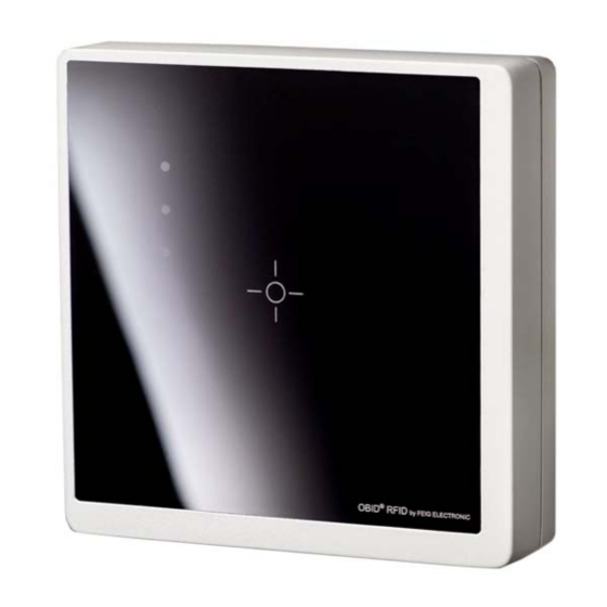
Feig Electronic OBID classic-pro Series Manual

Feig Electronic OBID classic-pro Series Manual

Rfid reader for iso / iec14443-a & -b, nfc and iso / iec15693
Hide thumbs Also See for OBID classic-pro Series:
Table of Contents

Advertisement

MANUAL
ID CPR30.xx
RFID Reader for ISO/IEC14443-A & -B, NFC and ISO/IEC15693
Up From Firmware Version 01.02.00
preliminary
public (B)
2011-08-18
H01114-0E-ID-B.doc

Advertisement

Table of Contents
loading

Summary of Contents for Feig Electronic OBID classic-pro Series

  • Page 1 MANUAL ID CPR30.xx RFID Reader for ISO/IEC14443-A & -B, NFC and ISO/IEC15693 Up From Firmware Version 01.02.00 preliminary public (B) 2011-08-18 H01114-0E-ID-B.doc...
  • Page 2 Composition of the information in this manual has been done to the best of our knowledge. FEIG ELECTRONIC GmbH does not guarantee the correctness and completeness of the details given in this manual and may not be held liable for damages ensuing from incorrect or incomplete information.
  • Page 3 Reader. The following figure formats are used: 0...9: for decimal figures 0x00...0xFF: for hexadecimal figures, b0...1 for binary figures. The hexadecimal value in brackets "[ ]" indicates a command. FEIG ELECTRONIC GmbH Page 3 of 126 H01114-0e-ID-B.docx...
  • Page 4: Table Of Contents

    4.2. [0x81] Write Configuration ....................36 4.3. [0x83] Set Default Configuration (Configuration RESET) ..........37 5. Command for Reader Control 5.1. [0x52] Baud Rate Detection ................... 38 5.2. [0x63] CPU Reset ......................38 FEIG ELECTRONIC GmbH Page 4 of 126 H01114-0e-ID-B.docx...
  • Page 5 6.4. Special Commands for Transponder Communication ..........83 6.4.1. [0xBD] ISO14443A Transparent Command ............... 83 6.4.2. [0xBE] ISO14443B Transparent Command ............... 88 7. [0xC0] SAM Commands 7.1. [0x01] SAM Activate / Deactivate ..................94 FEIG ELECTRONIC GmbH Page 5 of 126 H01114-0e-ID-B.docx...
  • Page 6 ANNEX C4: Error-Code for ISO15693 Transponders ............124 ANNEX D: Examples for Read Data ..................125 ISO-Host Command (DB-Size of the Transponder = 4Byte) ..........125 ISO-Host Command (DB-Size of the Transponder = 8Byte) ..........125 FEIG ELECTRONIC GmbH Page 6 of 126 H01114-0e-ID-B.docx...
  • Page 7: Revision History Of This Documentation

    ® OBID classic-pro Manual ID CPR30.xx Revision History of this documentation Revision Description Described Firmware: 01.00.00 – 01.02.00 Preliminary Version - Changes are not separate recorded. FEIG ELECTRONIC GmbH Page 7 of 126 H01114-0e-ID-B.docx...
  • Page 8: Abbreviations

    Least Significant Byte Minutes Milliseconds Most Significant Byte Number Output Read / Write Access Read Relay Radio Frequency Reserved for Future Use Transponder Timeslot Unique Identifier (read only Serial Number) Write Only Access Write FEIG ELECTRONIC GmbH Page 8 of 126 H01114-0e-ID-B.docx...
  • Page 9: Introduction

    Beside the CPRStart software for demonstration and configuration the reader capabilities and the ® OBID Firmware Update Tool a lot of different Software Development Kits (SDK) and drivers are available to support an easy integration into the customer’s application. FEIG ELECTRONIC GmbH Page 9 of 126 H01114-0e-ID-B.docx...
  • Page 10: Data Transmission Between Obid Id Cpr-Reader And Host

    EEPROM. After the Reader was powered up the configuration out of the EEPROM is used. Host (Terminal / PC / ..) Reader parameter- / control command parameter received and stored / control command processed status / error status data FEIG ELECTRONIC GmbH Page 10 of 126 H01114-0e-ID-B.docx...
  • Page 11: Iso Host Commands

    = Transponder read no Transponder data in Reader field write data to Transponder with UID Transponder with correct UID in antenna field? OK status status = no Transponder in Reader field FEIG ELECTRONIC GmbH Page 11 of 126 H01114-0e-ID-B.docx...
  • Page 12 Selected Transponder in antenna field? status / status = Transponder read no Transponder data in Reader field write data Selected Transponder in antenna field? OK status status = no Transponder in Reader field FEIG ELECTRONIC GmbH Page 12 of 126 H01114-0e-ID-B.docx...
  • Page 13: Data Format And Protocol Frames For Bi-Directional Communication

    If the response data will result a protocol frame with more than 255 Byte the Reader chose the advanced protocol frame otherwise the Reader chose the standard protocol frame. FEIG ELECTRONIC GmbH Page 13 of 126 H01114-0e-ID-B.docx...
  • Page 14: Standard Protocol Frame (Up To 255 Byte)

    2.3.2. Advanced Protocol Frame (recommended to use) Reader Host (6...n-2) COMMAND  COM-ADR (DATA) (0x02) ALENGTH ALENGTH - BYTE  CRC16 CRC16 Host Reader (7...n-2) COMMAND  COM-ADR STATUS (DATA) (0x02) ALENGTH ALENGTH - BYTE  CRC16 CRC16 FEIG ELECTRONIC GmbH Page 14 of 126 H01114-0e-ID-B.docx...
  • Page 15: Protocol Elements

    ALENGTH (n = 8...65535): Number of protocol bytes including STX, ALENGTH and CRC16 Data format: Start bits: Data bits: Stop bits: Parity: even (default) none see ANNEX C: Index of Status Bytes FEIG ELECTRONIC GmbH Page 15 of 126 H01114-0e-ID-B.docx...
  • Page 16: Timing Conditions

    // cnt = number of protocol bytes without CRC crc ^= DATA[i]; for (j = 0; j < 8; j++) if (crc & 0x0001) crc = (crc >> 1) ^ CRC_POLYNOM; else crc = (crc >> 1); FEIG ELECTRONIC GmbH Page 16 of 126 H01114-0e-ID-B.docx...
  • Page 17: Configuration Parameters (Cfg)

    Malfunctions may occur if parameters are configured outside their described range or if unspecified parameters have been changed! A firmware update resets the EEPROM to default settings and the Reader goes into the error status “EE-Init-mode”. FEIG ELECTRONIC GmbH Page 17 of 126 H01114-0e-ID-B.docx...
  • Page 18 Changing of this para- be changed, as this may cause meter only becomes faulty operation of the Reader. effective after writing / saving this configuration block to EEPROM and a Reader reset FEIG ELECTRONIC GmbH Page 18 of 126 H01114-0e-ID-B.docx...
  • Page 19: Cfg0: Rfu (Reserved For Future Use)

    0x00 0x00 0x00 0x00 0x00 0x00 0x00 Default 0x00 0x00 0x00 0x00 0x00 0x00 0x00 Byte Contents 0x00 0x00 0x00 0x00 0x00 0x00 0x00 Default 0x00 0x00 0x00 0x00 0x00 0x00 0x00 FEIG ELECTRONIC GmbH Page 19 of 126 H01114-0e-ID-B.docx...
  • Page 20: Cfg1: Interface

    0x81 bit/s 0x82 bit/s 0x83 bit/s NOTICE: A plausibility check is performed by writing this parameter to the Reader. If an error occurs the Reader an- swers with STATUS = 0x11. FEIG ELECTRONIC GmbH Page 20 of 126 H01114-0e-ID-B.docx...
  • Page 21 In this case, the current commands between Reader and Transponder are aborted. A plausibility check is performed by writing this parameter to the Reader. If an error occurs the Reader an- swers with STATUS = 0x11. FEIG ELECTRONIC GmbH Page 21 of 126 H01114-0e-ID-B.docx...
  • Page 22 The block receive timeout of host computer must set to a value TR-RESPONSE- TIME. READER-MODE: By means of this byte, the Reader mode can be defined. Bit: Function: Only ISOHost mode is available FEIG ELECTRONIC GmbH Page 22 of 126 H01114-0e-ID-B.docx...
  • Page 23: Cfg2: Inputs / Outputs General

    In case of polling mode the reader starts to signalize the offline state if it has re- ceived no command from the host for more than the time defined by the parameter OFFLINE-TIME. FEIG ELECTRONIC GmbH Page 23 of 126 H01114-0e-ID-B.docx...
  • Page 24 FLASHING SLOW TAGDETECT-ACTIVATION-TIME: This parameter defines the duration in 100 ms increments, the Reader signalize a trans- ponder was detected. 0 ... 255 x 100 ms 0 ... 25,5 sec FEIG ELECTRONIC GmbH Page 24 of 126 H01114-0e-ID-B.docx...
  • Page 25: Cfg3: Rf-Interface

    Transponder access is mini- mized. A plausibility check is performed by writing this parameter to the Reader. If an error occurs the Reader an- swers with STATUS = 0x11. FEIG ELECTRONIC GmbH Page 25 of 126 H01114-0e-ID-B.docx...
  • Page 26 ISO14443 STUPT (1 ... 255 * 5 ms = 5 ms ... 1,275 sec): The Startup Time defines a delay-time which is required by a ISO14443 Transponder for startup after the RF-Field was switched on (e. g. after a command [0x69] RF Reset). FEIG ELECTRONIC GmbH Page 26 of 126 H01114-0e-ID-B.docx...
  • Page 27 This parameter defines the maximum number of automatic retry loops in case of transmission or protocol errors as described in ISO 14443-4. b00: disables retry loop b01: 1 retry loop 2 retry loops b11: 3 retry loops FEIG ELECTRONIC GmbH Page 27 of 126 H01114-0e-ID-B.docx...
  • Page 28 The UID will be transferred as described in 6.1.1.1. Response-Data - ISO 14443A (TR-TYPE = 0x04). The byte order of the transferred UID will be swapped (UID transfer will be carried out like described in ISO14443). FEIG ELECTRONIC GmbH Page 28 of 126 H01114-0e-ID-B.docx...
  • Page 29: Cfg4: Transponder Parameters

    Tag Option = 0 b11: Tag Option = 1 NOTICE: If WR-OPTION is automatically set, the Reader sets the WR-OPTION to 0, if the ISO-Host Command is in non-addressed mode. FEIG ELECTRONIC GmbH Page 29 of 126 H01114-0e-ID-B.docx...
  • Page 30 A value of 0x00 will be automatically set to a block size of 4 Byte. Blocksize Automatic (If transponder is known) Manuel (As specified in DB-Blocksize) Read Mode b00: Automatic Mode (If transponder is known) Single Read Multiple Read FEIG ELECTRONIC GmbH Page 30 of 126 H01114-0e-ID-B.docx...
  • Page 31: Cfg5: Anticollision

    Transponders inside of the antenna field and replies the UID of all de- tected Transponder's. AORB_REQ: This parameter defines the abort conditions of the Inventory command [0x01] for ISO14443 Transponder if the ISO14443A and ISO14443B Transponder drivers are activated. FEIG ELECTRONIC GmbH Page 31 of 126 H01114-0e-ID-B.docx...
  • Page 32 The Inventory command stops if the UID of all ISO14443A or of all ISO14443B Transponders in the detection range are read. So the Inven- tory command returns either the presence of ISO14443A or ISO14443B Transponders. FEIG ELECTRONIC GmbH Page 32 of 126 H01114-0e-ID-B.docx...
  • Page 33: Cfg6

    ® OBID classic-pro Manual ID CPR30.xx 3.7. CFG6 .. 15: Reserved FEIG ELECTRONIC GmbH Page 33 of 126 H01114-0e-ID-B.docx...
  • Page 34: Cfg16: Persistence Reset

    After this time has expired the Reader resets the RF-Field. Timer ticks = 5ms Maximum timer value = 5ms x 65534[0xFFFE] = 5,46125 min. The value 65535 [0xFFFF] indicates that no RF-Reset is performed by the Reader FEIG ELECTRONIC GmbH Page 34 of 126 H01114-0e-ID-B.docx...
  • Page 35: Commands For Reader Configuration

    14-byte configuration block read from address CFGn in CFG-ADR. NOTICE: A read configuration from EEPROM with reserved configuration blocks will cause an 0x15 error code. see: ANNEX C: Index of Status Bytes see Chapter 3. Configuration Parameters (CFG) FEIG ELECTRONIC GmbH Page 35 of 126 H01114-0e-ID-B.docx...
  • Page 36: 0X81] Write Configuration

    14-byte configuration block stored in the configuration memory of the Reader at address CFGn. NOTICE: A write configuration to EEPROM with reserved configuration blocks will cause an 0x16 error code. see: ANNEX C: Index of Status Bytes see chapter 3. Configuration Parameters (CFG) FEIG ELECTRONIC GmbH Page 36 of 126 H01114-0e-ID-B.docx...
  • Page 37: 0X83] Set Default Configuration (Configuration Reset)

    Specifies the location of the configuration block. EEPROM Notes: To store RAM configuration over power down use Fehler! Verweisquelle konnte nicht ge- funden werden. A set default configuration with reserved configuration blocks will cause an error code. FEIG ELECTRONIC GmbH Page 37 of 126 H01114-0e-ID-B.docx...
  • Page 38: Command For Reader Control

    CRC16 (0x02) ALENGTH ALENGTH Host Reader 7...8 COM-ADR [0x63] CRC16 STATUS (0x02) ALENGTH ALENGTH Notes: The RF-field will be switched off while a CPU Reset. see: ANNEX C: Index of Status Bytes FEIG ELECTRONIC GmbH Page 38 of 126 H01114-0e-ID-B.docx...
  • Page 39: 0X64] System Reset

    (0x02) ALENGTH ALENGTH 12...13 14...15 16...17 18...19 HW-TYPE SW-TYPE TR-TYPE RX-BUF TX-BUF CRC16 SW-REV: Version of the firmware. see ANNEX C: Index of Status Bytes see: ANNEX C: Index of Status Bytes FEIG ELECTRONIC GmbH Page 39 of 126 H01114-0e-ID-B.docx...
  • Page 40 ERROR. TX-BUF: TX-BUF is the maximum transmit buffer size of the Reader. The host has to take in to ac- count that a response protocol of the Reader can have this length. FEIG ELECTRONIC GmbH Page 40 of 126 H01114-0e-ID-B.docx...
  • Page 41: 0X66] Get Reader Info

    SAM Information 0x12: CPU Information 0x80: Device-ID: Necessary Information's for firmware updates and firmware upgrades. Host Reader Depending on the MODE Parameter the reader response has a differing structure with sev- eral information. FEIG ELECTRONIC GmbH Page 41 of 126 H01114-0e-ID-B.docx...
  • Page 42: Mode = 0X00 (Rf Controller Firmware)

    Indicates the support of the T=CL Function (Command [0xB2][0xBE]) T=CL function is not supported T=CL function is supported see: ANNEX C: Index of Status Bytes see: ANNEX C: Index of Status Bytes FEIG ELECTRONIC GmbH Page 42 of 126 H01114-0e-ID-B.docx...
  • Page 43: Mode = 0X05 (Bootloader Version Information)

    No of available SAM slots. SLOT_INFO: Bit: CFG_NO Slot-Type inserted Slot-Type: 0000: Universal SAM socket for ID000 SAM inserted: No SAM inserted SAM is inserted see: ANNEX C: Index of Status Bytes FEIG ELECTRONIC GmbH Page 43 of 126 H01114-0e-ID-B.docx...
  • Page 44: Mode = 0X12 (Cpu Information)

    Indicates which Transponder drivers are licensed on the Reader. FNC_L: Indicates which optional functions are licensed on the Reader. see: ANNEX C: Index of Status Bytes see: ANNEX C: Index of Status Bytes FEIG ELECTRONIC GmbH Page 44 of 126 H01114-0e-ID-B.docx...
  • Page 45: 0X69] Rf Reset

    After the RF Reset command the Reader is not able to receive any new Transponder be- fore expiration of t After a RF Reset a Transponder which is located within the field has to be re-selected. see: ANNEX C: Index of Status Bytes FEIG ELECTRONIC GmbH Page 45 of 126 H01114-0e-ID-B.docx...
  • Page 46: 0X6A] Rf Output On/Off

    RF power at antenna 1. This setting is to use, if the reader has only one internal or one external antenna. see ANNEX C: Index of Status Bytes FEIG ELECTRONIC GmbH Page 46 of 126 H01114-0e-ID-B.docx...
  • Page 47: 0X72] Set Output

    Defines the number of output records. OUT-NR: Defines the type and the number of the output Bit: Function: OUT-Typ OUT-Number OUT-Typ: b001 b010 Buzzer OUT-Number: b001 LED green b010 LED yellow any other bit configuration is reserved FEIG ELECTRONIC GmbH Page 47 of 126 H01114-0e-ID-B.docx...
  • Page 48: Set Output Examples

    BUZZER is activated for 1000ms LED3 and RELAY are unchanged OUT-N OUT-NR OUT-S OUT-TIME 0x0003 0x21 0x03 0x0005   OUT-NR OUT-S OUT-TIME 0x22 0x00 0x0002   OUT-NR OUT-S OUT-TIME 0x41 0x01 0x000A FEIG ELECTRONIC GmbH Page 48 of 126 H01114-0e-ID-B.docx...
  • Page 49: Iso Host Commands For Transponder Communication

    Reader 5...n-2 n-1,n COM-ADR [0xB0] STATUS RESPONSE- CRC16 (0x02) ALENGTH ALENGTH DATA REQUEST-DATA: Command specific request RESPONSE-DATA: Command specific response Notes: Data are only transferred if STATUS = 0x00, 0x83, 0x94, 0x95. FEIG ELECTRONIC GmbH Page 49 of 126 H01114-0e-ID-B.docx...
  • Page 50: 0X01] Inventory

    Number of Transponder data sets to be transferred in this reader response. TR-TYPE: Bit: Function TYPE_NO TYPE_NO: Displays the Transponder type of the present Transponder (see: ANNEX A: Codes of Transponder Types). FEIG ELECTRONIC GmbH Page 50 of 126 H01114-0e-ID-B.docx...
  • Page 51: Response-Data - Iso 14443A (Tr-Type = 0X04)

    Depending on the setting of CFG3.ISO14443 FTUR.OPTI this byte could optional display further information's about the present Transponder. It's recommend to use this information if ISO14443-4 Transponder or Transponder with more the 4 byte UID length should be handled by the reader. FEIG ELECTRONIC GmbH Page 51 of 126 H01114-0e-ID-B.docx...
  • Page 52 The UID byte order can be swapped by using the parameter CFG3.ISO14443 FTUR.UID_ORDER In case of NXP mifare chips this byte also indicates the chip type. Further information's are given in the NXP Application Note "mifare Interface Platform, Type Identification Procedure" M018412. FEIG ELECTRONIC GmbH Page 52 of 126 H01114-0e-ID-B.docx...
  • Page 53: Response-Data - Iso 14443B (Tr-Type = 0X05)

    This parameter is extracted from the protocol Info bytes as described in ISO14443-3. Bit: Function Max_Frame_Size Protocol_Type Max_Frame_Size (according ISO14443-3:2001): Value Frame Size (Byte) RFU > 256 Protocol_Type (according ISO14443-3:2001): Meaning PICC compliant with ISO/IEC 14443-4 PICC not compliant with ISO/IEC 14443-4 FEIG ELECTRONIC GmbH Page 53 of 126 H01114-0e-ID-B.docx...
  • Page 54: Response-Data - Iso15693 (Tr-Type = 0X03)

    Displays the Transponder type of the present Transponder (see: ANNEX A: Codes of Transponder Types). DSFID: (only ISO15693Transponders) Data Storage Family Identifier. UID: ISO 156963 UID. It is transmitted by the reader with a length of 8 byte. FEIG ELECTRONIC GmbH Page 54 of 126 H01114-0e-ID-B.docx...
  • Page 55: Sequences Of Inventory Command And Iso14443 Transponder

    Response 2 one Transponder ISO14443 Transponders on ISO14443-3 level (see 6.3. [0xB2] ISO14443 Special Host Commands) ISO14443-4 Commands Response 3 one Transponder (see 6.3. [0xB2] ISO14443 Special Host Commands on ISO14443-4 level FEIG ELECTRONIC GmbH Page 55 of 126 H01114-0e-ID-B.docx...
  • Page 56: 0X25] Select

    UID_LEN. CINF: don't return card-information return the card-information within the select response. DRV_SEL: No extra byte TR-DRV included in request data Extra byte TR-DRV included in request data FEIG ELECTRONIC GmbH Page 56 of 126 H01114-0e-ID-B.docx...
  • Page 57 UID field. NOTICE: The maximum UID_LEN is limited depending on the reader type. If UID_LEN exceeds the internal buffer size the reader responses a error massage. FEIG ELECTRONIC GmbH Page 57 of 126 H01114-0e-ID-B.docx...
  • Page 58 Indicates the format of the CARD_INFO field: 0x00: No further CARD_INFO field available. 0x01: CARD_INFO of an ISO14443-4 Type-A Transponder. 0x02: CARD_INFO of an ISO14443-4 Type-B Transponder. 0x03: CARD_INFO of an ISO14443-3 Type-A Transponder. FEIG ELECTRONIC GmbH Page 58 of 126 H01114-0e-ID-B.docx...
  • Page 59 FORMAT = 0x03 CARD_INFO contains the ATQA and SAK parameter after the anticollision loop has finished of ISO14443 Type-A Transponder as defined in ISO14443-3. ATQA Proprietary coding UID size RFU Bit frame anticollision FEIG ELECTRONIC GmbH Page 59 of 126 H01114-0e-ID-B.docx...
  • Page 60: 0X02] Stay Quiet

    This command sets one Transponder to Quiet State. REQUEST-DATA 8-15 0x02 MODE MODE: Bit: Function ADR: b001 addressed UID: Read-only serial number of the Transponder. Note: This command is only available for ISO15693 Transponders. FEIG ELECTRONIC GmbH Page 60 of 126 H01114-0e-ID-B.docx...
  • Page 61: 0X22] Lock Multiple Blocks (Extended Address Mode)

    Transponder memory addressing is done by the 1 byte DB-ADR Field. Transponder memory addressing is done by BANK and 2 byte DB-ADR Field UID: Read-only serial number of the Transponder. The UID is required only in the addressed mode. FEIG ELECTRONIC GmbH Page 61 of 126 H01114-0e-ID-B.docx...
  • Page 62 Standard Protocol (TX-BUF - 12 )/(DB-Size+1) Advanced Protocol ISO15693 ERROR: ISO15693 ERROR code of Transponder response. This byte is only available if STATUS = 0x95. DB-ADR-E: Block number where the error occurred. FEIG ELECTRONIC GmbH Page 62 of 126 H01114-0e-ID-B.docx...
  • Page 63: 0X22] Lock Multiple Blocks

    TX-BUF. The maximum number of DB-N is: (TX-BUF - 10 )/(DB-Size+1).ISO15693 ERROR: ISO15693 ERROR code of Transponder response. This byte is only available if STATUS = 0x95. DB-ADR-E: Block number where the error occurred. FEIG ELECTRONIC GmbH Page 63 of 126 H01114-0e-ID-B.docx...
  • Page 64: 0X23] Read Multiple Blocks (Extended Address Mode)

    Transponder memory addressing is done by the 1 byte DB-ADR Field. Transponder memory addressing is done by BANK and 2 byte DB-ADR Field UID: Read-only serial number of the Transponder. The UID is required only in the addressed mode. FEIG ELECTRONIC GmbH Page 64 of 126 H01114-0e-ID-B.docx...
  • Page 65 A read from 1 block uses a Read Single Block command to the Transponder. If a Transponder does not support Read Multiple Blocks commands several Read Single Block commands are used for this Transponder. Only one Transponder can be read in the non-addressed mode. FEIG ELECTRONIC GmbH Page 65 of 126 H01114-0e-ID-B.docx...
  • Page 66: 0X23] Read Multiple Blocks

    Number of data blocks to be read from the Transponder, starting at DB_ADR. The maxi- mum number of DB-N, depends on DB-Size. The maximum number of bytes is 128 byte. DB-Size Max. DB-N = 128 / x ISO-ERROR: Additional error code if STATUS = 0x95. FEIG ELECTRONIC GmbH Page 66 of 126 H01114-0e-ID-B.docx...
  • Page 67 A read from 1 block uses a Read Single Block command to the Transponder. If a Transponder does not support Read Multiple Blocks commands several Read Single Block commands are used for this Transponder. Only one Transponder can be read in the non-addressed mode. FEIG ELECTRONIC GmbH Page 67 of 126 H01114-0e-ID-B.docx...
  • Page 68: 0X24] Write Multiple Blocks (Extended Address Mode)

    Transponder memory addressing is done by the 1 byte DB-ADR Field. Transponder memory addressing is done by BANK and 2 byte DB-ADR Field UID: Read-only serial number of the Transponder. The UID is required only in the addressed mode. FEIG ELECTRONIC GmbH Page 68 of 126 H01114-0e-ID-B.docx...
  • Page 69 If a Transponder does not supports Write Multiple Blocks commands several Write Single Block commands are used for this Transponder. A write command on I-Code 1 Transponders can only be performed in the addressed mode. FEIG ELECTRONIC GmbH Page 69 of 126 H01114-0e-ID-B.docx...
  • Page 70 ® OBID classic-pro Manual ID CPR30.xx If an error occurred during a write command, the number of the block where the error oc- curred will be send to host FEIG ELECTRONIC GmbH Page 70 of 126 H01114-0e-ID-B.docx...
  • Page 71: 0X24] Write Multiple Blocks

    Read-only UID of the Transponder. The UID is required only in the addressed mode. DB_ADR: Address of the first data block to be written to the Transponder. First block can be any val- ue between 0 and 255. FEIG ELECTRONIC GmbH Page 71 of 126 H01114-0e-ID-B.docx...
  • Page 72 If a Transponder does not support Write Multiple Blocks commands several Write Single Block commands are used for this Transponder. If an error occurred during a write command, the number of the block were the error oc- curred will be send to host FEIG ELECTRONIC GmbH Page 72 of 126 H01114-0e-ID-B.docx...
  • Page 73: 0Xb0] Iso 14443 Standard Host Commands

    8. Supported ISO Host commands. REQUEST-DATA [0xC0] MODE MODE: Bit: Function ADR: b010 selected NOTICE: If anticollision is enabled the Reader sets the Transponder into the Halt status itself. FEIG ELECTRONIC GmbH Page 73 of 126 H01114-0e-ID-B.docx...
  • Page 74: 0Xb2] Iso14443 Special Host Commands

    Reader 7...n-2 n-1,n COM-ADR [0xB2] STATUS RESPONSE- CRC16 (0x02) ALENGTH ALENGTH DATA REQUEST-DATA: Command specific request RESPONSE-DATA: Command specific response Notes: This command isn’t available if the notification/max mode is switched on. FEIG ELECTRONIC GmbH Page 74 of 126 H01114-0e-ID-B.docx...
  • Page 75: 0Xbe] Iso 14443-4 T=Cl (#)

    - 256 byte for data sending from Host to Reader (downlink) - 256 byte (FSDI = 8) for data sending from Reader to Host (uplink). REQUEST-DATA (8...n-2) [0xBE] MODE (DATA) RESPONSE-DATA (8...9) (10...n-2) STATUS (PSTAT) (BLK_CNT) (DATA) FEIG ELECTRONIC GmbH Page 75 of 126 H01114-0e-ID-B.docx...
  • Page 76 The CID has to be placed in DATA directly behind the MODE Parameter NOTICE: In case of command chaining (see Bit "MORE") only the CID in the first command block is accepted by the Reader. FEIG ELECTRONIC GmbH Page 76 of 126 H01114-0e-ID-B.docx...
  • Page 77 The present protocol block is the second or further part of a chained command. The present protocol block is a single command or the first part of a chained command. FEIG ELECTRONIC GmbH Page 77 of 126 H01114-0e-ID-B.docx...
  • Page 78 The DATA Field could be used to transfer the optional CID, NAD and INF Field of the ISO14443-4 communication protocol. In most cases the INF Field carries an APDU to the Transponder. FEIG ELECTRONIC GmbH Page 78 of 126 H01114-0e-ID-B.docx...
  • Page 79 This response is given by the Reader to re-trigger the receive timeout of the host. This response could occur if an error in data exchange between Transponder and Reader had happened and the Reader retries the process by it self. STATUS PSTAT BLK_CNT 0x94 0xFF 0xXX FEIG ELECTRONIC GmbH Page 79 of 126 H01114-0e-ID-B.docx...
  • Page 80 Error, Error-Codes) BLK_CNT: The BLK_CNT is a block counter which indexes each transmission from the Reader to the Host. On basis of the BLK_CNT the host could proof and sort the received protocols. FEIG ELECTRONIC GmbH Page 80 of 126 H01114-0e-ID-B.docx...
  • Page 81: 0Xbf] Iso 14443-4 Container Command (#)

    The Reader will send the command and is waiting for a response form the Trans- ponder while the time period defined in TIMEOUT is running or the Transponder had send a response. FEIG ELECTRONIC GmbH Page 81 of 126 H01114-0e-ID-B.docx...
  • Page 82 1 Byte 1 Byte x Byte 2 Byte NOTICE: PCB is mandatory for each command whereas the parameters in [ ] brackets are op- tional. For further Information please see ISO/IEC ISO14443-4 FEIG ELECTRONIC GmbH Page 82 of 126 H01114-0e-ID-B.docx...
  • Page 83: 0X2B] Iso14443-4 Transponder-Info

    Displays the present supported data transfer rate from Transponder to Reader. kBit / s NAD: NAD (Node Address) supported, if bit is set to 1. CID: CID (Card Identifier) supported, if bit is set to 1. FEIG ELECTRONIC GmbH Page 83 of 126 H01114-0e-ID-B.docx...
  • Page 84: Special Commands For Transponder Communication

    STATUS  (0x02) ALENGTH ALENGTH Mode 0 +1 7...n-2 n-1,n  RESPONSE- CRC16 DATA Mode 2 8...n-2 n-1,n  RSP-BITS RESPONSE- CRC16 DATA Mode 3 9...n-2 n-1,n  RSP-BITS RESPONSE- CRC16 DATA FEIG ELECTRONIC GmbH Page 84 of 126 H01114-0e-ID-B.docx...
  • Page 85 If RSP-LENGTH is set to “0” the Reader will send the command but not wait for any re- sponse. If RSP-LENGTH is not equal to “0” the Reader will send the command and return the response data of the Transponder without SOF and EOF. FEIG ELECTRONIC GmbH Page 85 of 126 H01114-0e-ID-B.docx...
  • Page 86 4948 ms 15..254 - not allowed - NOTICE: The value of TIMEOUT must be considered for calculating the HOST-TIMEOUT. The value of TIMEOUT must be considered for calculating the TR-RESPONSE-TIME (see CFG1). FEIG ELECTRONIC GmbH Page 86 of 126 H01114-0e-ID-B.docx...
  • Page 87 No CRC is checked The last byte(s) of a received frame is/are interpreted as CRC byte/s Examples: Command CRC-INFO comment REQA 0x01 Parity, no TxCRC, no RxCRC HALT 0x0D Parity, TxCRC, RxCRC FEIG ELECTRONIC GmbH Page 87 of 126 H01114-0e-ID-B.docx...
  • Page 88 “RxCRCEn” is “1”. However if “RxCRCEn” is “0”the transponder CRC is transferred with the response data. RSP-BITS: Number of valid Bits in RESPONSE-DATA NOTICE: Data is only transferred if STATUS = 0x00, 0x02, 0x83, 0x84, 0x94. FEIG ELECTRONIC GmbH Page 88 of 126 H01114-0e-ID-B.docx...
  • Page 89: 0Xbe] Iso14443B Transparent Command

    * (8 data bits). The LSB of each byte is transmitted first. end of communication 1 = bit oriented frame with variable bitrates Bit oriented frames with variable Tx- and Rx-Bitrates FEIG ELECTRONIC GmbH Page 89 of 126 H01114-0e-ID-B.docx...
  • Page 90 4948 ms 15..254 - not allowed - NOTICE: The value of TIMEOUT must be considered for calculating the HOST-TIMEOUT. The value of TIMEOUT must be considered for calculating the TR-RESPONSE-TIME (see CFG1). FEIG ELECTRONIC GmbH Page 90 of 126 H01114-0e-ID-B.docx...
  • Page 91 EGT Setting no EGT after last character EGT after each character Examples: Command FRAME comment REQB 0x2D SOF: 10 ETU low and 3 ETU high, EOF-Length = 11 ETU, EGT = 1 FEIG ELECTRONIC GmbH Page 91 of 126 H01114-0e-ID-B.docx...
  • Page 92 RxCRCEn No CRC is checked The last byte(s) of a received frame is/are interpreted as CRC byte/s Example: Command CRC-INFO comment REQB 0x0C No Parity, TxCRC, RxCRC FEIG ELECTRONIC GmbH Page 92 of 126 H01114-0e-ID-B.docx...
  • Page 93 “RxCRCEn” is “1”. However if “RxCRCEn” is “0” the transponder CRC is transferred with the response data. NOTICE: Data is only transferred if STATUS = 0x00, 0x02, 0x83, 0x84, 0x94. FEIG ELECTRONIC GmbH Page 93 of 126 H01114-0e-ID-B.docx...
  • Page 94: 0Xc0] Sam Commands

    1..255: timeout in 100 ms increments. The host application has to consider the SC_TIMOUT for setting the timeout on host side. REQUEST-DATA: Command specific request (see sub-commands in the following chapters) RESPONSE-DATA: Command specific response FEIG ELECTRONIC GmbH Page 94 of 126 H01114-0e-ID-B.docx...
  • Page 95: 0X01] Sam Activate / Deactivate

    This setting activates the addressed smartcard temporary and can be used to evaluate ATR string of the inserted smartcard. Notice: This mode deactivates an activated smartcard. see: ANNEX C: Index of Status Bytes FEIG ELECTRONIC GmbH Page 95 of 126 H01114-0e-ID-B.docx...
  • Page 96 The supported baudrates are shown in Fehler! Verweisquelle konnte nicht gefunden werden. Bit: Function Indicator value of the clock rate conversion factor according ISO 7816-3. Indicator value of the baud rate adjustment factor according ISO 7816-3. FEIG ELECTRONIC GmbH Page 96 of 126 H01114-0e-ID-B.docx...
  • Page 97: 0Xbd] T=0 Data Exchange

    This bit specifies the data transfer direction of the current command. Transmit data to SAM Receive data from SAM CLA: APDU instruction class byte. INS: APDU instruction APDU parameter byte 1 APDU parameter byte 2 see: ANNEX C: Index of Status Bytes FEIG ELECTRONIC GmbH Page 97 of 126 H01114-0e-ID-B.docx...
  • Page 98 Introduces no data transfer. TR_REC: = b1 (receive data) Introduces a 256 byte data transfer from the smartcard. DATA: APDU command or response data. SW1, SW2: Status Code returned by the card. FEIG ELECTRONIC GmbH Page 98 of 126 H01114-0e-ID-B.docx...
  • Page 99: 0Xbe] T=1 Data Exchange

    The EDC field is build internally by the reader RSP_DATA: Response to the T1 block from the card (if any). The EDC field is not included in RSP_DATA. see: ANNEX C: Index of Status Bytes FEIG ELECTRONIC GmbH Page 99 of 126 H01114-0e-ID-B.docx...
  • Page 100: Supported Iso Host Commands

    NOTICE: Detailed data sheets and information's about the functions and capabilities of each Trans- ponder type are not supplied by FEIG ELECTRONIC. For detailed information's we refer to the original data sheets of the chip manufacturer. 8.1. ISO14443-A & -B Part 4 compatible Transponder 8.1.1.
  • Page 101: Nxp - Mifare Desfire

    DESFire EV1 (2k: MF3 IC D21, 4k: MF3 IC D41, 8k: MF3 IC D81) Command Function Mode Comment Code non- addressed selected addressed [0xB0] [0x01] Inventory [0xB0] [0x25] Select [0xB2] [0xBE] ISO14443-4 T=CL [0xB2] [0xBF] ISO14443-4 Container [0xB2] [0x2B] ISO14443-4 Transponder-Info FEIG ELECTRONIC GmbH Page 101 of 126 H01114-0e-ID-B.docx...
  • Page 102: Iso14443-A Part 3 Compatible Transponder

    Mode Comment Code non- addressed selected addressed [0xB0] [0x01] Inventory [0xB0] [0x23] Read Multiple Blocks DB-Size = 8 [0xB0] [0x24] Write Multiple Blocks DB-Size = 8 [0xB0] [0x25] Select [0xB0] [0xC0] Halt FEIG ELECTRONIC GmbH Page 102 of 126 H01114-0e-ID-B.docx...
  • Page 103: Infineon - My-D Move Sle66R01P

    [0xBD] ISO14443A Transparent Command or by with using the OBID ® C++ Class Library ID FEDM up from version 3.01.00 (see document H10202-##-ID-B) of OBID software development kit. FEIG ELECTRONIC GmbH Page 103 of 126 H01114-0e-ID-B.docx...
  • Page 104: Nxp - Mifare Classic: Mini, 1K, 4K / Mifare Plus (Level 1)

    4k (MF1PLUS80) Number of blocks user area: 215 Block size 16 byte Command Function Mode Comment Code non- addressed selected addressed [0xB0] [0x01] Inventory [0xB0] [0x25] Select [0xB0] [0xC0] Halt FEIG ELECTRONIC GmbH Page 104 of 126 H01114-0e-ID-B.docx...
  • Page 105: Nxp - Mifare Ultralight

    Function Mode Comment Code non- addressed selected addressed [0xB0] [0x01] Inventory Security Status is always [0xB0] [0x23] Read Multiple Blocks 0x00 [0xB0] [0x24] Write Multiple Blocks [0xB0] [0x25] Select [0xB0] [0xC0] Halt FEIG ELECTRONIC GmbH Page 105 of 126 H01114-0e-ID-B.docx...
  • Page 106: Nxp - Mifare Plus Level 3

    AES Sector Keys for sector 0 to 39 (40 00h to 40 4Fh) Key A = sector number multiplied by 2 Key B = sector number multiplied by 2 +1 E.g. Key A for sector 2 has number: 40 04 FEIG ELECTRONIC GmbH Page 106 of 126 H01114-0e-ID-B.docx...
  • Page 107: Iso15693 Compatible Transponder

    0x2A Lock DSFID 0x2B Get System Information Get Multiple Block Security 0x2C Status The WR-OPTION will be set automatically by the FEIG Readers if the RW-OPTION parameter in “3.5. CFG4: Transponder Parameters” FEIG ELECTRONIC GmbH Page 107 of 126 H01114-0e-ID-B.docx...
  • Page 108: Fujitsu (Mb89R116)

    Parameters” is set to “00: automatically set”. Up to two blocks of data can be written for one request. ASK SUB-CARRIER must be configured in the reader (see: “3.5. CFG4: Transponder Pa- rameters”) FEIG ELECTRONIC GmbH Page 108 of 126 H01114-0e-ID-B.docx...
  • Page 109: Fujitsu (Mb89R118)

    Security Status is always (max. 2 Blocks) 0x00 DB-Size = 8, Fast Write Multiple Blocks 0xC4 WR-OPTION = 0 or 1 (max. 2 Blocks) 0xD1 Fast Write EAS Fast Read Multiple Blocks 0xD5 Unlimited FEIG ELECTRONIC GmbH Page 109 of 126 H01114-0e-ID-B.docx...
  • Page 110 The WR-OPTION will be set automatically by the FEIG Readers if the RW-OPTION parameter “3.5. CFG4: Transponder Parameters” is set to “00: automatically set”. Up to two blocks of data can be written for one request. FEIG ELECTRONIC GmbH Page 110 of 126 H01114-0e-ID-B.docx...
  • Page 111: Infineon (My-D Page Mode) 0X60

    The WR-OPTION will be set automatically by the FEIG Readers if the RW-OPTION parameter in “3.5. CFG4: Transponder Parameters” The Custom Specific Commands Read [0x10], Write [0x30] and the Write Byte [0x90] will be used automatical- ly by the Reader. FEIG ELECTRONIC GmbH Page 111 of 126 H01114-0e-ID-B.docx...
  • Page 112: Infineon (Iso Address Mode) 0Xe0

    WR-OPTION = 0 * The WR-OPTION will be set automatically by the FEIG Readers if the RW-OPTION parameter in “CFG4 Transponder Parameters” is set to “00: automatically set” (3.5. CFG4: Transponder Parameters). FEIG ELECTRONIC GmbH Page 112 of 126 H01114-0e-ID-B.docx...
  • Page 113: Ksw Microtec (Tempsens, Variosens)

    0x24 Write Multiple Blocks 0x25 Select 0x26 Reset to Ready 0x27 Write AFI 0x28 Lock AFI 0x29 Write DSFID 0x2A Lock DSFID 0x2B Get System Information Get Multiple Block Security 0x2C Status FEIG ELECTRONIC GmbH Page 113 of 126 H01114-0e-ID-B.docx...
  • Page 114: Nxp (I-Code Sli)

    Get Multiple Block Security 0x2C Status The WR-OPTION will be set automatically by the FEIG Readers if the RW-OPTION parameter in “CFG8 General” is set to “00: automatically set” (3.5. CFG4: Transponder Parameters). FEIG ELECTRONIC GmbH Page 114 of 126 H01114-0e-ID-B.docx...
  • Page 115: Stmicroelectronics (Lri512)

    Get Multiple Block Security 0x2C Status The WR-OPTION will be set automatically by the FEIG Readers if the RW-OPTION parameter in “CFG8 General” is set to “00: automatically set” (3.5. CFG4: Transponder Parameters). FEIG ELECTRONIC GmbH Page 115 of 126 H01114-0e-ID-B.docx...
  • Page 116: Stmicroelectronics (Lri64)

    Get System Information Get Multiple Block Security 0x2C Status The WR-OPTION will be set automatically by the FEIG Readers if the RW-OPTION parameter in “CFG8 General” is set to “00: automatically set” ” FEIG ELECTRONIC GmbH Page 116 of 126 H01114-0e-ID-B.docx...
  • Page 117: Texas Instruments (Tag-It Hf-I Plus)

    By using the “non-addressed ” mode the WR-OPTION must be set manually to “WR-OPTION = 1”. Note: The “Write_2_Blocks” command and “Lock_2_Blocks” command will be used automati- cally by the Reader. This will only become an effect if the block address starts with an even-numbered address. FEIG ELECTRONIC GmbH Page 117 of 126 H01114-0e-ID-B.docx...
  • Page 118 ® OBID classic-pro Manual ID CPR30.xx In the case of writing/locking an odd number of blocks the “Write_2_Blocks”/“Lock_2_Blocks” command will be combined with the “write single Block”/ “Lock single Block” command. FEIG ELECTRONIC GmbH Page 118 of 126 H01114-0e-ID-B.docx...
  • Page 119: Texas Instruments (Tag-It Hf-I Standard, Tag-It Hf-I Pro)

    The WR-OPTION will be set automatically by the FEIG Readers if the WR-OPTION parameter in “CFG4 Transponder Paramters” is set to “00: automatically set” (3.5. CFG4: Transponder Parameters). Note: Only one block is allowed for Read Multiple Blocks in non addressed mode FEIG ELECTRONIC GmbH Page 119 of 126 H01114-0e-ID-B.docx...
  • Page 120: Annex

    0x01 0x03 Transponder according ISO15693 0x04 Transponder according ISO14443A 0x05 Transponder according ISO14443B 0x06 NXP I-Code EPC 0x08 Innovision Jewel 0x0A STMicroelectronics SR176 0x0B STMicroelectronics SRIxx (SRI512, SRIX512, SRI4K, SRIX4K) 0x0E Keyboard FEIG ELECTRONIC GmbH Page 120 of 126 H01114-0e-ID-B.docx...
  • Page 121: Annex B: Codes Of Reader Types

    ID ISC.MRU200 ID ISC.MRU200-U ID ISC.LRU1000 ID ISC.LRU2000 ID CPR.M02 ID CPR.02 ID CPR40.30-Ux ID CPR40.0x-Ax / -Cx ID CPR.M03 (586/#) ID CPR.03 (584/#) ID CPR30 ID CPR.04 (596/#) ID CPR.04-U ID ISC.MR102 FEIG ELECTRONIC GmbH Page 121 of 126 H01114-0e-ID-B.docx...
  • Page 122: Annex C: Index Of Status Bytes

    The EEPROM of the Reader is not able to be written on. Before writing onto the EEPROM a faulty checksum of parameters has been detected. 0x11 Parameter-Range-Error: The value range of the parameters was exceeded. FEIG ELECTRONIC GmbH Page 122 of 126 H01114-0e-ID-B.docx...
  • Page 123 A data transmission error occurred while communication with the SAM 0x36 Timeout The Reader got no response from SAM within the defined timeout 0x37 Unsupported SAM Baudrate The used parameter of Fi and/or Di are not supported by the reader FEIG ELECTRONIC GmbH Page 123 of 126 H01114-0e-ID-B.docx...
  • Page 124: Annex C2: Iso14443-Error, Error-Codes

    ERROR-SOURCE = 3: ERROR- Status CODE 0x901E an error occurs while authentication, MAC calculation or CRC calculation. The reason can be a not satisfied security status or any kind of transmission errors. FEIG ELECTRONIC GmbH Page 124 of 126 H01114-0e-ID-B.docx...
  • Page 125: Annex C4: Error-Code For Iso15693 Transponders

    The specified block is locked and its content cannot be changed 0x13 The specified block was not successfully programmed 0x14 The specified block was not successfully locked 0xA0 - 0xDF Custom command error codes all others reserved for future use FEIG ELECTRONIC GmbH Page 125 of 126 H01114-0e-ID-B.docx...
  • Page 126: Annex D: Examples For Read Data

    ANNEX D: Examples for Read Data The setting "LSB first" and "MSB first" gives the direction of the received data bytes ISO-Host Command (DB-Size of the Transponder = 4Byte) ISO-Host Command (DB-Size of the Transponder = 8Byte) FEIG ELECTRONIC GmbH Page 126 of 126 H01114-0e-ID-B.docx...

This manual is also suitable for:

Obid id cpr30 series

Table of Contents