Table of Contents
Advertisement
EnCal 3000 Controller
Technical Documentation
Function, Operation,
Commissioning and Maintenance
2008 Elster GmbH
2008/2013
Advertisement
Table of Contents

Related Manuals for Elster EnCal 3000


Summary of Contents for Elster EnCal 3000
- Page 1 EnCal 3000 Controller Technical Documentation Function, Operation, Commissioning and Maintenance 2008 Elster GmbH 2008/2013...
- Page 2 Copyright: 2008 Elster GmbH GAS-WORKS and FLOW COMP are registered trademarks of Elster. Microsoft, Windows and Windows NT are registered trademarks of Microsoft Corporation. HART is a registered trademark of HART Communication Foundation. Elster GmbH Schloßstraße 95a D - 44357 Dortmund / Germany Tel.:...
-
Page 3: Table Of Contents
Primer for Impatient Operators: What do I have to do to ..................15 ... view the process values of the second stream in case of a dual-stream EnCal 3000 Controller? ....15 ... view the error listing of the Gas Quality module? ................... 15 ... -
Page 4: Table Of Contents
11.1 Error Listing of the Gas Quality Module ......................93 11.2 Menu Structure of the EnCal 3000 Controller ....................95 11.3 Certificate of Conformity ............................ 96 11.4 ATEX Certificate EXMFE5 ..........................97 11.5 ATEX Certificate EXDE6 ..........................103 Bibliography ................................107 Index .................................. - Page 5 This documentation describes the function, operation, commissioning and maintenance of the EnCal 3000 Controller. This controller is part of the EnCal 3000 Gas Quality Measurement System, which also consists of the EnCal 3000 Gas Chromatograph (GC). When mentioned within this documentation, “EnCal 3000” or “controller” always refers to the EnCal 3000 Controller.
-
Page 7: Introduction
The basic configuration of the EnCal 3000 gas quality measuring system consists of the EnCal 3000 Gas Chromatograph and the EnCal 3000 Controller (see Figure 1 below). When running EnCal 3000 Quad is the meter is in two cases and can contain up to four analytical channels. (see Figure 2 below). - Page 8 V.24 serial controller: Gasworks Controller (optional) passive unit e.g. stream 3, 4 Modbus ASCII/RTU (RS232/485) V.24 serial Modbus TCP (ethernet 10Base-T) Controller (optional) passive unit e.g. stream 5 V.24 serial ethernet 10Base-T Figure 1 Figure 2 page 2 EnCal 3000...
-
Page 9: The Encal 3000 Controller
The EnCal 3000 Controller is equipped with up to two digital data interfaces of the DSfG type (DSfG stands for Digital Interface for Gas Metering Device), which is used by all devices in the Elster gas-net device family as described below. -
Page 10: The Gas-Net System Idea
Each gas-net device always covers a multitude of measurement and control functionalities. EnCal 3000 Controllers also provide this functional variety. To keep the operation and parameterization of the devices well-structured and user-friendly, the gas-net series is based on a modular concept. A module corresponds to a special functionality. -
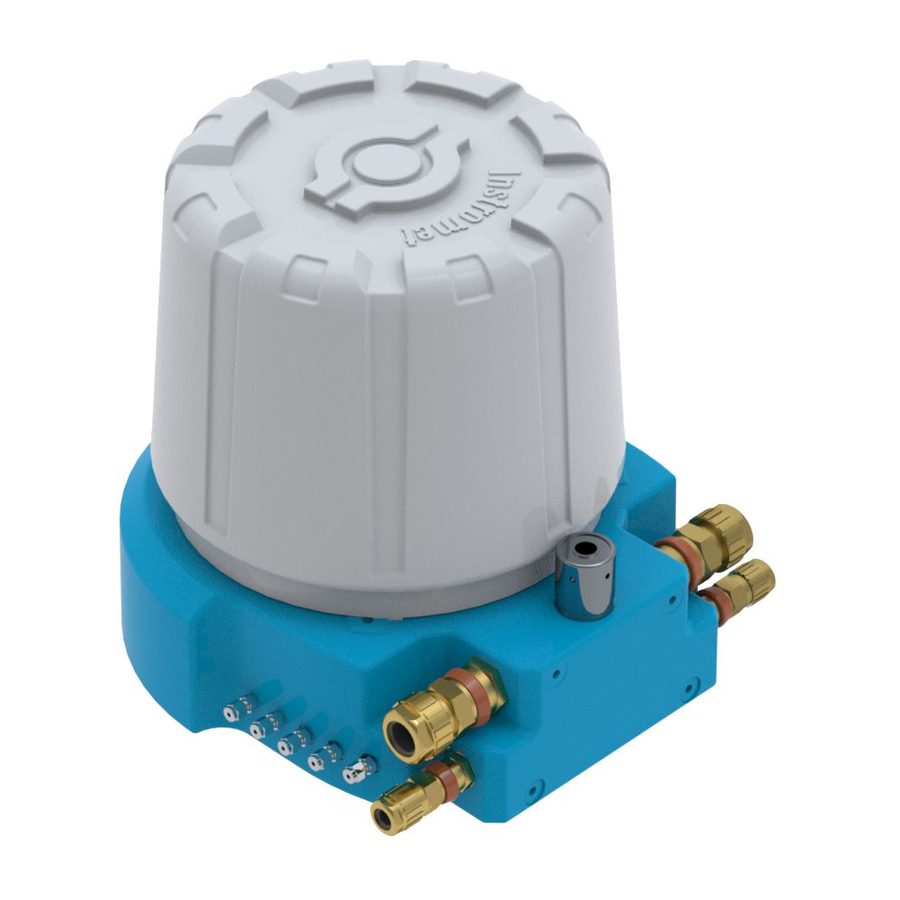
Page 11: Device View And Design
2 Device View and Design The housing of the EnCal 3000 Controller is designed as plug-in unit for a 19” frame and is usually available in two housing sizes, i.e. with a mounting width of 1/3 for up to four process boards or a mounting width of 1/2 for up to seven process boards. - Page 12 KARTE 3 BOARD KARTE 4 BOARD CPU V2 Optional digital interfaces, top: with the choice of DSfG or COM2 bottom: with the choice of TCP, DSfG or COM2 with caption (label) each. EnCal 3000 Controller rear view (example) page 6 EnCal 3000...
-
Page 13: Operating The Device
It can be removed from the error listing by accepting it. A warning has been pending but is no longer relevant. yellow, permanently illuminated It can be removed from the error listing by accepting it. The device runs error-free. green, permanently illuminated EnCal 3000 page 7... - Page 14 The calibration switch is on the lower right side of the front panel. The EnCal 3000 Controller is furnished with a two-level safety concept: All parameters being protected by the calibration switch can only be changed if the calibration switch is open. Such parameters are always modified with a PC and the GW-GNET+ parameterization software.
- Page 15 The structure of a module’s submenu listing depends on the current parameterization: Menu items referring to functionalities that have not been parameterized will not be offered for selection. For example: If the EnCal 3000 Gas Chromatograph is connected to only one stream, the gas quality module will not include the Other stream menu item.
- Page 16 It’s the System module in our example. Module listing: The System module has been selected. Press the Enter key and the display of the module you have just selected will be invoked. Basic display of the System module page 10 EnCal 3000...
- Page 17 Our destination, the Locks menu, is the third entry in the menu listing. Therefore, press the rightward arrow key twice to select the Locks line. The Locks menu has been selected. Press the Enter key afterwards to confirm your selection and invoke the related display. EnCal 3000 page 11...
- Page 18 Choose a suitable value from the listing via the arrow keys and accept it by pressing the Enter key. For example: Opening the revision switch of an EnCal 3000 Controller. (Note: This is only possible if the locks are open!). You can change the status of the revision switches in the Switches menu of the Monitoring module.
- Page 19 In this case, too, a consistency check is performed: If you have entered a value that does not make sense in the present context or is not permissible, you will not be able to quit the edit mode. You will have to correct your entry first. EnCal 3000 page 13...
-
Page 21: Primer For Impatient Operators: What Do I Have To Do To
Note: The EnCal 3000 Controller can be operated with one or two streams, i.e. it can indicate the analysis values of up to two gas streams of an EnCal 3000 Gas Chromatograph (GC). As the GC can be equipped with up to five streams, the streams to be indicated on the display must be selected. -
Page 22: Accept Gas Quality Errors
To accept such an error, proceed as follows: Open the error listing via the Menu key as described above in Chapter 4.2. If the EnCal 3000 Controller is operated with more than one stream, please ensure that the error listing of the desired stream is indicated. The third line of the display indicates the stream to which the currently invoked error listing refers. -
Page 23: To View The Software Versions
Activate the View submenu. The following special feature applies to an EnCal 3000 operated with two streams: An error referring to both streams disappears from both gas quality error listings as soon as it has been accepted in one of the listings. An example of such an error is alarm A409: Power failure. -
Page 24: Checking All Parameter Settings
Please note: The Change parameters or Edit parameterization service programs also offer the option of changing device settings. The current status of the protection mechanisms (calibration switch / user lock) is of course taken into consideration. Please refer to the comprehensive online help of GW-GNET+ for further information. page 18 EnCal 3000... -
Page 25: View Archives
Enter key. Select exactly the archive information you want to view in the appearing dialog. Please refer to Chapter 5.2.2 starting on page 41 for a detailed description of the filter function. EnCal 3000 page 19... -
Page 27: Functional Description
Function The EnCal 3000 Controller is a device for indicating and controlling the measurement of the gas quality (GQ) of natural gases by the gas chromatograph (GC) of the same name (EnCal 3000 Gas Chromatograph). The GC uses the different adsorptions rates of the individual components contained in the sample gas, which are separated from each other on their way through the integrated GC column. - Page 28 Gas Streams The EnCal 3000 Controller can indicate the analysis results of one or two gas streams of the EnCal 3000 Gas Chromatograph. In this case it contains one or two Gas Quality modules. The analysis results of either the first or the second gas quality module are updated in the controller, depending on the assignment of the current analysis result of the gas chromatograph to the respective gas stream.
- Page 29 The following figure shows an example for the basic display during an error-free operation: “Down“ scroll arrow pointing downwards: Scroll downwards with the rightward arrow key. Measurements for: Nitrogen Methane Ethane Propane I-butane N-butane Neopentane I-pentane N-pentane Hexane and higher hydrocarbons End of analysis EnCal 3000 page 23...
- Page 30 5.1.2.3 Measurements Display The EnCal 3000 Controller has an own display for indicating all gas quality data belonging to the current gas stream. This data comprises direct measurements as supplied by the main display and further derived measurement variables. Invoke this display as follows: Invoke the menu in the basic display.
- Page 31 The EnCal 3000 Controller always indicates new measurements here after the EnCal 3000 Gas Chromatograph has finished a measurement within its sequence. This measuring sequence is the automatic iterative measurement of the preset gas streams. It continues independently after you have started it once. You can start it either via the PC software (RGC 3000) of the EnCal 3000 Gas Chromatograph or from the EnCal 3000 Controller as follows: Invoke the menu and confirm the selected Start sequence entry by pressing the Enter key.
- Page 32 You can start the basic calibration only manually. Usually, you perform it when commissioning the device for the first time, whereas the automatic calibration is performed automatically and daily during operation at a parameterizable time. However, you can also start it manually at the EnCal 3000 Controller or remotely via a remote operating panel or the DSfG bus.
- Page 33 PC software (RGC 3000) of the EnCal 3000 Gas Chromatograph (cf. Chapter 5.4 in the EnCal 3000 Gas Chromatograph Software Manual). If you press the Menu key again, the following submenu appears: Select the Cal. start entry.
- Page 34 Confirm your selection and open the menu again. Select Cal. Cancel and confirm your selection. The EnCal 3000 Gas Chromatograph interrupts the calibration now (at the end of the current analysis) and returns to the normal operating conditions. The gas chromatograph then carries on working with the old calibration data.
- Page 35 (see analysis time). The target values are read out of the gas chromatograph and must be entered via the PC software (RGC 3000) of the EnCal 3000 Gas Chromatograph (c.f. Chapter 5.4 in the EnCal 3000 Gas Chromatograph Software Manual).
- Page 36 The analysis results determined during the calibration are entered in the Calibration archive. If you want to abort the calibration prematurely, do so as described below: While in the main display, invoke the menu via the Menu key and select Calibration. page 30 EnCal 3000...
- Page 37 The injection of test gases serves to check the gas chromatograph with a known gas or to measure unknown gases on a non-routine basis. It can only be started manually. The calibration switch at the EnCal 3000 Controller does not need to be open for this. If user locks have been parameterized, however, they must be open.
- Page 38 150 s purging time before the first analysis within the test gas sequence 180 s per analysis within the test gas sequence. A test gas sequence always consists of one measurement. page 32 EnCal 3000...
- Page 39 Confirm your selection and open the menu again. Select Test gas cancel and confirm your selection. The EnCal 3000 Gas Chromatograph interrupts the test gas run now (at the end of the current analysis) and returns to the normal operating conditions.
- Page 40 A listing with the gas quality data of the test gas to be used appears. You can enter all values via the display: To edit a value, get into the edit mode by pressing the Enter key. page 34 EnCal 3000...
- Page 41 If you select OK, all values are used as new target values of the test gas. By selecting Cancel you return to the Test gas menu without accepting values you have possibly edited before. In this case, the target values that were valid before you have opened the Enter target values submenu are still valid. EnCal 3000 page 35...
- Page 42 Different gases must be available in the station for calibration and measurement tasks. From time to time, it is therefore necessary to connect a new gas cylinder to a gas supply connection of the EnCal 3000 Gas Chromatograph; for instance, if the pressure of the calibration gas cylinder is insufficient.
- Page 43 5.1.6 Revision The EnCal 3000 Controller sets the revision status when test gas is injected. A set revision status means that the gas quality is not measured under normal, proper operating conditions. All entries in the Hourly mean bill archive are therefore marked with the Revision status note. Furthermore, the Revision/Test Gas hint is generated and entered in the error listing and logbook.
- Page 44 Press the Enter key again to quit the selection mode. Only by quitting the Switches menu you finally confirm whether you want to accept the new switch settings or reject them. For this, open the menu by pressing the Menu key: page 38 EnCal 3000...
- Page 45 Switches menu. If you have set the revision status by means of the revision switch, it will be indicated on the display just like during a test gas run and signaled to the corrector. EnCal 3000 page 39...
-
Page 46: Data Logging Module
5.2 Data Logging Module 5.2.1 Function EnCal 3000 Controllers are always equipped with an integrated data logging function. The responsible Data Logging module, however, provides only the data logging service. The actual data to be logged is generated by other modules of the module group. - Page 47 Invoke the selected archive via the menu (see next section). Status stands for a bit string that provides an overview of the EnCal 3000 Controller’s status. Each individual measurement variable of an archive group logged by a device additionally has an ordinal number for reasons of unambiguity.
- Page 48 PC before; for example via the data interface by means of the GAS-WORKS module GW-REMOTE+. You can view the data afterwards in a table or as a diagram with the GW-DATA+ program. page 42 EnCal 3000...
-
Page 49: Monitoring Module
The beginning of a hint is entered in the error listing together with a time mark. Hints cannot be accepted and automatically disappear from the error listing after they have ended. A complete listing of all errors together with their classification is included in the annex to this documentation. EnCal 3000 page 43... - Page 50 LED does not show which stream is affected. You can always obtain detailed information via the error listings. The software of the EnCal 3000 Controller includes a revision switch to facilitate a system check by revision. You can activate this revision switch via the operator panel at the device if the user locks are open.
- Page 51 The different message types of a group are called Group message, Held group message and Centralized message. The DSfG data elements for message processing are included in the DSfG data element tree of the Control entity. Please ask Elster for a precise list of the supported or used DSfG data elements, when required.
- Page 52 The following illustration shows how, according to procedure 1, the centralized message of a group classified as No acceptance required differs from the one of a group classified as Acceptance required. page 46 EnCal 3000...
- Page 53 The M-switch is activated via an assigned digital input. It cannot be set via the operator panel for safety reasons. Status and signaling reactions of single messages remain unaffected by the M-switch. Single messages are suppressed via the disabling mechanism explained above. EnCal 3000 page 47...
- Page 54 The following illustration shows the behavior of the main signaller in connection with the acceptance (in case of one involved group): Group Single message M1 Single message M2 Acceptance Acceptance Main signaller message page 48 EnCal 3000...
- Page 55 Logging on Measurement or Counter Archives The EnCal 3000 Controller is able to keep archives for process values, i.e. archives for measurements and count values. Up to four archive groups with up to 8 channels each are available. You can determine for each archive group individually in which conditions the contained archive channels shall be logged.
- Page 56 An alarm has the highest priority level, i.e. it is of greatest importance. A warning has a higher priority level than a hint. Cf. Chapter 5.3.1 for an explanation of the terms Alarm, Warning and Hint. page 50 EnCal 3000...
- Page 57 Measurements An EnCal 3000 Controller can have up to 32 parameterized measurements for maximum/minimum indication on file. If you invoke the related display, the first measurement is indicated. You can switch to the display of another measurement via the name.
- Page 58 As the Name selection list contains all single messages of the corresponding group you can switch to the indication of any other single message of the currently selected group. page 52 EnCal 3000...
- Page 59 Whether a single message is being routed at all depends on the fact whether the message is disabled or enabled: If a single message has been disabled, the entire subsequent message processing considers it as not pending. EnCal 3000 page 53...
- Page 60 The Disabled messages menu described here merely provides information. Please switch to the Single messages menu (see above) if you want to disable or enable a single message. This is the last submenu of the Monitoring module: Switches (for changing switch outputs and the revision status) page 54 EnCal 3000...
- Page 61 Messages of the Switch type can be routed to digital outputs (cf. Chapter 5.5.1) to trigger switching operations of any kind from the EnCal 3000 Controller. Four switches are available (Switch 1 to Switch 4). To change the status of a switch you need to invoke the Switches menu of the Monitoring module.
-
Page 62: Integrated Rdt Module
If the device is equipped with a DSfG interface, further devices can be connected via this interface. If such a local DSfG bus exists, the connection to the center not only refers to the communication with the entities of the EnCal 3000 Controller but with the entire local DSfG bus traffic. - Page 63 A center that also supports DSfG queries via TCP/IP network is required for this operating mode; e.g. GW-Remote+. The use of the TCP/IP network is advantageous for applications provided with a nearby IP network. The modem and telephone network can then be saved. EnCal 3000 page 57...
- Page 64 In case of a TCP/IP connection the display shows the host IP and the dynamically allocated port number instead. page 58 EnCal 3000...
- Page 65 However, no data was exchanged as the center did not switch into the transparency mode. GSM (only if a wireless modem is connected) EnCal 3000 page 59...
- Page 66 With the menu item synchronize now the internal device time can be synchronized immediately. This is only possible if the synchronization status is waiting for end of interval or dialing pause. If the calibration switch is closed, it is impossible to start synchronize now. page 60 EnCal 3000...
-
Page 67: System Module
DSfG is a digital interface especially developed for data communications between gas meters (such as gas-net devices). The EnCal 3000 Controller can be equipped with a DSfG interface as an option. The DSfG bus is connected via the connector labeled DSfG on the back of the device. - Page 68 After you have activated the Inputs menu item, the first channel of the input board will always be indicated at board location 1. The display indicates the following information: The usability of these procedures in dependence on local conditions has to be clarified in advance with Elster. According to the DSfG specification: W810: Clock set old;...
- Page 69 Get into the edit mode by pressing the Enter key to switch to the display of another channel. A listing with the names of all parameterized output channels appears. After you have chosen the desired output channel and pressed the Enter key, the display of the selected channel will be invoked. EnCal 3000 page 63...
- Page 70 GPS or NTP for diagnostic purposes. Note: The Protocols display is not intended for host protocols being processed by the Data Exchange module; please refer to the corresponding module display for information on these protocols. page 64 EnCal 3000...
- Page 71 (see above). All pieces of data shown in further lines are intended for diagnosis by experts; please refer to the documentations and specifications of the respective measuring instrument manufacturers or contact Elster. EnCal 3000 page 65...
- Page 72 DSfG bus. Caution: If several devices are connected to the bus, you have to select the operating mode depending on the slowest station. If the bus communication does not work, the EnCal 3000 Controller may have been parameterized with a baud rate that is too high.
- Page 73 ) of the EnCal 3000 Controller’s internal entities Known stations: Known stations indicates the EADRs of all bus stations currently known to the EnCal 3000 Controller. If a general polling has not yet taken place or there is no local DSfG bus available, only the stations within the EnCal 3000 Controller can be known as being connected to the bus.
- Page 74 General polling If one of the entities within the EnCal 3000 Controller is the bus master (the station with the EADR “_”), you can trigger a general polling via this menu item. If there is no master operation, the menu cannot be activated.
- Page 75 Display test menu item, the pixels of the display are alternately switched on and off. At the same time the status LED shows all three colors after each other. Finish the display test via Back. EnCal 3000 page 69...
-
Page 76: Dsfg Module, Data Exchange Module
The DSfG protocol is a digital data protocol that has been particularly developed for communication between gas meters in gas measuring and regulating stations. If the EnCal 3000 Controller is equipped with a DSfG interface, all important measurements and characteristics are provided via DSfG protocol. The contents of DSfG data elements can be internally queried and provided without a physical DSfG interface, too. -
Page 77: Gw-Gnet
Adjust the settings according to your requirements. Please refer to the GAS-WORKS CD-ROM, which is part of the delivery scope of each device of Elster, for further information on the GAS-WORKS program system with all the possibilities it provides. All GAS-WORKS components can be installed from this CD. - Page 78 2. Drag the data record with the mouse from the worksheet into the right half of the configuration window. Alternatively, drag the data record directly to a folder in the hierarchy (on the left side of the configuration window). Refer to the online help for more detailed information. page 72 EnCal 3000...
-
Page 79: Importing And Editing A Parameterization: Brief Description
6.2 Importing and Editing a Parameterization: Brief Description You can read out the current parameterization of an EnCal 3000 Controller via the data interface and edit it afterwards. Import the parameterization as follows: Connect the DSS data interface of the EnCal 3000 Controller and the COM interface of the PC using a parameterization cable. -
Page 80: Extras: Gw-Gnet+ Service Programs
The functional range of the service programs is manageable and practical. The operation is thus rather easy. A comprehensive online help is also available for each program. It can be activated via the Help – Content menu item or by pressing the F1 key. page 74 EnCal 3000... -
Page 81: Installation
7.1 Mounting the EnCal 3000 Controller The EnCal 3000 Controller device is designed for mounting in a 19”-cabinet and is available with mounting widths of 1/3 or 1/2. Please pay attention to a mounting depth of 170 mm (with connectors: approximately 220 mm) to guarantee the accessibility of the terminals on the back. - Page 82 The cable shielding for all transmitter lines is placed on the SH terminal at the EXMFE5 input board. Please consult Elster if you want to connect sensors via HART protocol and the cable is longer than 50 m. page 76...
- Page 83 Signal ground Shield If the communication with the EnCal 3000 Gas Chromatograph is realized via Modbus serial (RTU or ASCII) over RS232 or RS485 the device contains a MSER2 board. Other applications of a serial MSER2 channel are the connection of a host computer via RK512/3964R or MODBUS protocol or the connection of a GPS receiver for time synchronization.
- Page 84 I-). The terminals named LA and LE on top of the board are reserved for later expansions (LA = fiber-optics output, LE = fiber-optics input). Connect the cable shielding to the SH terminal of the board. page 78 EnCal 3000...
- Page 85 A standard COM connection (one-to-one connection) is not permissible. 7.2.3.2 DSfG Interface (optional) The DSfG interface at the EnCal 3000 Controller is a SUB-DB 9 male connector located on the back of the device. Secure the connector with screws. 7.2.3.3 TCP/IP Interface (optional) The TCP/IP interface is an RJ45 socket on the back of the device.
- Page 86 Select the antenna depending on the determined data signal quality and preferably after consultation with Elster. The following specifications are guidelines:...
- Page 87 From left to right: 1: earth (ground) 2: unassigned 3: +24 V 4: unassigned 5: unassigned 6: +24 V The illustration shows a Siemens M20 wireless modem, but holds by analogy for the Siemens modem type TC35. EnCal 3000 page 81...
-
Page 89: Commissioning
8.1 Parameter Protection against Unauthorized Access The functionality of the EnCal 3000 Controller can be completely configured via a parameter data record. Unauthorized persons must therefore be prevented from changing these parameters. In order to guarantee this protection, the EnCal 3000 Controller is provided with a two-level security system consisting of the Calibration lock (official safeguarding) and the Locks (user locks, password protection). -
Page 90: Commissioning The Integrated Rdt
If an entity of the gas-net device is the bus master, initiate the general polling via the operator panel at the device: Switch to the main display of the System module. Invoke the menu and select the subordinate menu item DSfG. Press the Menu key again and confirm the subordinate menu item General polling. page 84 EnCal 3000... - Page 91 Remove the DSfG connector on the back of the gas-net device if a local DSfG bus exists. Disconnect the wireless modem from the supply and pull the V24 cable off the EnCal 3000. Check whether the V24 cable is plugged in the modem. Test the antenna installation (has the antenna been connected?).
- Page 92 To initiate such a connection request, you have to trigger an event first that induces the RDT to call; e.g. an alarm in the gas-net device. The connection will then be established as described above. See Footnote 28, page 70 page 86 EnCal 3000...
-
Page 93: Maintenance
9 Maintenance The EnCal 3000 Controller does not require much maintenance. 9.1 Battery Replacement The device battery mainly runs down when the device is switched off. The battery consumption can be neglected as long as the device is switched on. -
Page 95: Technical Data: Encal 3000 Controller
Electronic gas quality measurement device as display for the EnCal 3000 Gas Chromatograph with integrated data logging function. Each EnCal 3000 Controller can process one or two gas streams. If the EnCal 3000 Controller takes on the active role within the Modbus communication with the EnCal 3000 Gas Chromatograph, you can also use it to perform manual calibrations or test gas runs. - Page 96 Each interface can be configured to RS232, RS485 or RS422 by a suitable assignment of the interface terminals. Implemented protocols: Modbus RTU, Modbus ASCII, Siemens 3964R, Q.Sonic ultrasonic gas meter protocol of Elster. Furthermore, it is possible to connect a FLOWSIC ultrasonic gas meter of SICK/MAIHAK or a GPS receiver for time synchronization.
- Page 97 Modbus-TCP protocol for exchanging data with external devices are also possible via the TCP/IP interface. Optional DSfG interface for data transmission between gas-net devices. Correction and data logging archives pollable via DSfG. EnCal 3000 page 91...
-
Page 99: Annex
A409 Power failure The EnCal 3000 Controller generates the Power failure alarm in case of a mains failure. It is pending until the device starts up again after the mains has returned. During this time the incoming analysis information (from the GC) is not evaluated. - Page 100 H2000 Modbus error Hint H2000 is generated directly after the start-up of the EnCal 3000 Controller if an error has occurred in the parameterization of the Modbus communication. For instance, the selected Modbus version (RTU or ASCII) must be the same in the parameterization of the controller and in the Modbus set-up of the gas chromatograph (cf.
-
Page 101: Menu Structure Of The Encal 3000 Controller
11.2 Menu Structure of the EnCal 3000 Controller Within the main display of a module, you may open the listing of the subordinate menu items by pressing the menu button . By pressing the button again, the menu with the listing of all available modules is opened. -
Page 102: Certificate Of Conformity
11.3 Certificate of Conformity page 96 EnCal 3000... -
Page 103: Atex Certificate Exmfe5
11.4 ATEX Certificate EXMFE5 EnCal 3000 page 97... - Page 104 98 EnCal 3000...
- Page 105 EnCal 3000 page 99...
- Page 106 100 EnCal 3000...
- Page 107 EnCal 3000 page 101...
- Page 108 102 EnCal 3000...
-
Page 109: Atex Certificate Exde6
11.5 ATEX Certificate EXDE6 EnCal 3000 page 103... - Page 110 104 EnCal 3000...
- Page 111 EnCal 3000 page 105...
- Page 112 106 EnCal 3000...
-
Page 113: Bibliography
12 Bibliography ISO 12213-3 / ISO 12213-3: Natural gas – Calculation of compression factor DIN EN 50014, DIN EN 50020 and DIN EN 50029 DIN 19 235: Measurement and control; signalling of operating conditions EnCal 3000 page 107... -
Page 115: Index
DSfG bus address 67 Certificate of conformity 96 DSfG entity 67 Changed settings archive 40 DSfG interface 61, 79 COM2 interface 79 DSfG menu 66 Commissioning 83 DSfG requester 70 Integrated RDT 84 DSfG requester module EnCal 3000 page 109... - Page 116 Controller 3, 89 Antenna 80 Gas chromatograph 1 Signal quality 60 Gas quality measuring system 1 Installation 75 GW-GNET+ 71 EnCal 3000 Controller Service programs 74 Operating 7 View and design 5 HART transmitter 76 EnCal 3000 Rechner Held group message 46...
- Page 117 M-switch 47 Process value archives 49 Freezing 49 Nachrichtentyp 67 Protocols New message 52 Display 64 No acceptance required 46, 47 Purging 36 Null modem 57 Null modem 57 Operating 7 via modem or GSM 56 Operation EnCal 3000 page 111...
- Page 118 Software version View 17 Status Warning 43 Revision/Test gas 31, 37 Warning notes v Status bit string 41 Wireless modem M20 / TC35 Status LED 7 Connection to 24 V 81 Streams 22 Synchronize clock 62, 69 page 112 EnCal 3000...
Need help?
Do you have a question about the EnCal 3000 and is the answer not in the manual?
Questions and answers