
Related Manuals for Elster EnCal 3000

Summary of Contents for Elster EnCal 3000
- Page 1 EnCal 3000 Gas Chromatograph Hardware Manual 73022344 LC 05.10.2016 ___________________________________________________________________________________________________________ EnCal 3000 – Hardware Manual 05/10/2016...
-
Page 2: Table Of Contents
Connections to the EnCal 3000 Interconnection board ............. 41 Hardware Start-up ..........................44 APPENDIX 1: Possible hardware options of the EnCal 3000 ............... 46 APPENDIX 2: DECLARATION OF CONFORMITY ENCAL 3000 .............. 53 APPENDIX 3: CERTIFICATE EC-Type Examination ................57... -
Page 3: Contact Information
Tel. ++49 (0) 231 93 71 10-88 e-mail: system.Support-DO@elster.com Aftersales /Service International: Elster-Instromet N.V. Rijkmakerlaan 9 2910 Essen Belgien / Belgium Tel. ++32 (0) 3 6 700 700 e-mail: aftersales@elster-instromet.com Or your local agent: www.elster-instromet.com ___________________________________________________________________________________________________________ EnCal 3000 - Hardware Manual 05/10/2016 3/61... -
Page 4: Safety Information
Elster GmbH Safety Information Electrical Safety The EnCal 3000 is a gas analyser designed to be installed in hazardous areas. For this purpose it is certified according to: ATEX II 2 G Ex-d IIC T6 Gb Ex-d IIC T6 Gb... - Page 5 Installation instructions mentioned in this manual are intended for information only. The installation of this equipment must conform to any national, local, or company codes applicable to the location. Elster-Instromet assumes no responsi- bility for compliance with these requirements. It is suggested that a review of the codes be made prior to installation.
-
Page 6: Gas Quality Measurement System Encal 3000
Elster GmbH Gas quality measurement system EnCal 3000 The gas quality measurement system EnCal 3000 consists in its basic configuration of a measuring unit and an optional Encal3000 controller. The measuring unit is the real gas chromatograph. It performs the analysis by measuring technology auton- omously. -
Page 7: Process Gas Chromatography - General Introduction
The concentration of each component is then measured at the end of the column by a detector. From the knowledge of the concentrations of each component, any property of the gas can be calculated. ___________________________________________________________________________________________________________ EnCal 3000 - Hardware Manual 05/10/2016 7/61... -
Page 8: Column
(for example type M5S mole sieve) Porous layer open tubular column: the stationary phase is a porous layer on the inner wall of the col- umn (for example type PPU) ___________________________________________________________________________________________________________ EnCal 3000 - Hardware Manual 05/10/2016 8/61... -
Page 9: Detector
1 ppm for n-pentane. Traditionally the two TCD’s (reference + measurement detector) are integrated in a so-called Wheatstone configuration, which increases significantly the signal-to-noise ration of the measurement. fig. 1-3 Typical electrical TCD circuit ___________________________________________________________________________________________________________ EnCal 3000 - Hardware Manual 05/10/2016 9/61... -
Page 10: Sample Injector
MEMS sample injector, etched in silicon channel, with membrane valves to control flow directions. This injector allows for a very precise control of the injection volume and temperature, on a remote base. fig. 1-4 MEMS Sample Injector ___________________________________________________________________________________________________________ EnCal 3000 - Hardware Manual 05/10/2016 10/61... -
Page 11: Process Gas Chromatography
The EnCal 3000 is designed to meet or exceed all of the above requirements. At the same time the unit uses analytical technology which can compete with the highest standards used in the laboratory world, surpassing any PGC currently used in the natural gas industry. -
Page 12: Functional Design
Functional Design Introduction The EnCal 3000 is an on-line gas chromatograph that is housed in an EX-proof housing. In the housing is place for up to two analytical channels that are controlled by one processor board. The most important features are:... -
Page 13: Enclosure
Elster GmbH Enclosure The enclosure of the EnCal 3000 is a custom EX design, with various spe- cific features. Essentially the explosion proof enclosure consists of a low base, to which a relatively high cap is attached through a screw connection. Once the cap is... -
Page 14: Assembly Of Major Components And Internal Components
The detailed description of the functionalities of each component will be done in the following paragraphs. fig. 2-1 Exploded View on the Internal Parts of the EnCal 3000 ___________________________________________________________________________________________________________... -
Page 15: Channel
Channel A channel consists of the following subcomponents: Analytical Module: This is the heart of the EnCal 3000: it contains the column, sample injector, detector and the heaters for the columns and the injector AMI (Analytical Module Interface): electronic circuit which controls the analytical components of the Analytical Module. - Page 16 Elster GmbH fig. 2-2 Overview of Channel Components The next page shows the internal gas flow configuration of the channels. ___________________________________________________________________________________________________________ EnCal 3000 - Hardware Manual 05/10/2016 16/61...
- Page 17 Elster GmbH fig. 2-3 Internal Gas Flow Circuit for each Analytical Channel of the EnCal 3000, during Normal Operation (top) and sample Injection (below) ___________________________________________________________________________________________________________ EnCal 3000 - Hardware Manual 05/10/2016 17/61...
- Page 18 Pump sample valve Sample vent Sample fig. 2-4 Internal Gas Flow Circuit for each Analytical Channel with backflush of the EnCal 3000, before activating backflush valve (top) and after activating backflush valve (below) ___________________________________________________________________________________________________________ EnCal 3000 - Hardware Manual 05/10/2016...
-
Page 19: Processor Board
Changes in the parameters can only be transferred to the measuring unit, if the jumper is not set. The setting of the jumper, can be checked on the display of the “instrument status” page. See Section 3.2 of the software manual. How to set the jumper is shown in Figure 2.6. ___________________________________________________________________________________________________________ EnCal 3000 - Hardware Manual 05/10/2016 19/61... - Page 20 2-5 Save parameters in the measuring unit all bord versions When installed in the EnCal 3000, a flat cable makes the connection between the communication ports of the Processor Board and the Interconnection Board, which provides field connections (Phoenix connector) for the data communication signals.
-
Page 21: Interconnection Board
Enclosure temperature regulation Internal DC/DC conversion for various circuits fig. 2-7 Interconnection Board The following diagram shows the overall electrical configuration EnCal3000 in a rough overview. fig. 2-8 Overall Electrical Configuration of the EnCal 3000 ___________________________________________________________________________________________________________ EnCal 3000 - Hardware Manual 05/10/2016... -
Page 22: Cabinet Heaters
10 °C (50 °F). Figure 2.10 shows the location of the cabinet heaters. fig. 2-9 Cabinet heaters location in the EnCal 3000 For the regulation of the heaters standard thermostats with a fixed setting are used. These thermostats are connected to the interconnection board close to the connectors for the power supply of the heaters (see also fig. -
Page 23: Internal Sample System
Helium the chance of internal damage is also reduced significantly. The purge and the small amount of helium that is vented into the housing also protects the internal components against moisture or other aggressive components entering the housing through the breather. ___________________________________________________________________________________________________________ EnCal 3000 - Hardware Manual 05/10/2016 23/61... - Page 24 Elster GmbH fig. 2-11 Flow diagram Sample Conditioning and Selection System ___________________________________________________________________________________________________________ EnCal 3000 - Hardware Manual 05/10/2016 24/61...
-
Page 25: Double Block And Bleed Function
After the sample gas has passed the manifold it becomes split for the transport to the two analytical channels. The vent outputs from both modules return to the mani- fold and are combined to two venting outputs. ___________________________________________________________________________________________________________ EnCal 3000 - Hardware Manual 05/10/2016 25/61... -
Page 26: Gas Connections
Its length has to be bigger than 25 cm (19") and should not be shortened by the customer fig. 2-12 Gas Connection of the EnCal 3000. Adapter includes 2µ filter. WARNING! DO NOT LOOSEN THE CONNECTORS (AS DESCRIBED ABOVE) FROM THE ENCAL 3000 HOUSING. -
Page 27: 2.10 Breather
It has an outlet connection of 1/4 NPT. It’s made from Stainless steel GKN SIKA R40. Bubble test pore size Max. 80 µm; Density Minimum 3.5g/cm³; Thickness Minimum 13mm. Any tube connected should have an internal cross section of at least 28mm² 3/8” tube or larger. ___________________________________________________________________________________________________________ EnCal 3000 - Hardware Manual 05/10/2016 27/61... -
Page 28: 2.11 Cable Entries
For connection of an external earthling or bonding conductor a cable lug shall be used. The conductor shall be mounted so that it is secured against loosening and twisting and that the contact pres- sure is permanently maintained. ___________________________________________________________________________________________________________ EnCal 3000 - Hardware Manual 05/10/2016 28/61... -
Page 29: 2.12 External Switch
Device". Practical implementation of this requirement will differ from site to site. In any case the external switch installa- tion has to comply with all national, local, and company codes applicable to the location. ___________________________________________________________________________________________________________ EnCal 3000 - Hardware Manual 05/10/2016 29/61... -
Page 30: 2.13 Configuration With Two Carrier Gases
PPU Helium is used as carrier gas. In the following picture this configuration is shown. The two connections for the two different carrier gases are marked on the housing. fig. 2-16 Configuration with two Carrier Gases ___________________________________________________________________________________________________________ EnCal 3000 - Hardware Manual 05/10/2016 30/61... -
Page 31: Technical Specifications
API Report 21.1. All data available on remote workstation in XML format Remote monitoring and trending of the system as an integral part of the Instromet Supervi- sory Suite ___________________________________________________________________________________________________________ EnCal 3000 - Hardware Manual 05/10/2016 31/61... - Page 32 : 0.001 – 0.05 % COS : 0.0001 – 1% : 0.001 – 0.05% : 0.001 – 0.05 % Concentrations outside this scope might be possible, but verification with Elster- Instromet is needed. Performance Uncertainty < 0.1 % for all calculated properties Repeatability <...
- Page 33 Power Supply / Data Communication / Ext. sensors (optional) M20/M25 cable gland for armoured cable per default Diameters Ø 5.5-12 mm / Ø 12.5-20 mm / Ø 17-26 mm Optionally with adapters to NPT or other sizes. ___________________________________________________________________________________________________________ EnCal 3000 - Hardware Manual 05/10/2016 33/61...
-
Page 34: Data Communication
Local TCP/IP Data Communication The main Data Communication Port of the EnCal 3000 is the TCP/IP port, although 2 serial ModBus ports are also avail- able (see next paragraph). The TCP/IP Port (Ethernet UTP 10 Base-T) is necessary for connection with RGC 3000 (Win- dows based interface for configuration, diagnostics and report generation), but is also used by preference for ModBus communication with Flow Computers, PLC and other ModBus hosts, if they are able to handle ModBus TCP/IP. -
Page 35: Local Serial Modbus Data Communication
Flow computers or another ModBus host could also be directly connected to one of the 2 serial ModBus ports internally integrated in the EnCal 3000. fig. 4-2 Typical Data Communication Set-up for TCP/IP combined with Serial ModBus Communication with the EnCal 3000 ___________________________________________________________________________________________________________ EnCal 3000 - Hardware Manual... -
Page 36: Remote Access
Elster GmbH Remote Access The schematic below shows the different options for remote access to the EnCal 3000: Through Internet: Or through a direct connection of the Ethernet switch with Internet (through cable or ADSL modem, or wire- less) Or through a VPN connection with the customer’s network, if the Ethernet switch or the local PC is integrated in this network. -
Page 37: Modbus Communication
Elster GmbH ModBus Communication The picture below shows the ModBus Configuration screen for the EnCal 3000 (see also Software Manual) fig. 4-4 ModBus Configuration Screen The ModBus registers are user configurable: fig. 4-5 ModBus Register Details Register Type: Either Read Only (R) or Read/Write (R/W), and either bit (Status) or register size Register #: User selectable. -
Page 38: Hardware Installation
: Ø 37 x H 37 cm (Ø 14.5" x H 14.5”) Installation Clearance : Ø 50 x H 70 cm (Ø 20" x H 28”) 5.1.2 Installation clearance fig. 5-1 Mounting Dimensions and Installation Clearance fig. 5-2 Mounting Holes EnCal 3000 Housing ___________________________________________________________________________________________________________ EnCal 3000 - Hardware Manual 05/10/2016 38/61... -
Page 39: Wall Mounting
Wall mounting fig. 5-3 Wall Mounting Bracket Dimensions Depending on local regulations, the weight of the EnCal 3000 (±28kg) may exceed the allowable manual lifting limit for one person. Be sure the appropriate manpower or lifting equipment and protective equipment such as safety shoes are available. -
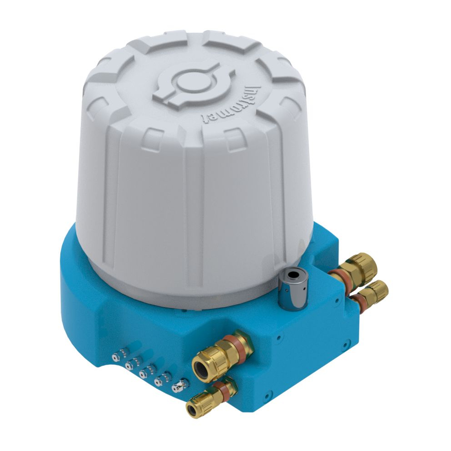
Page 40: Connection Of Utilities
1-4 barg (15-57 PSIg) Purge Vent Sample + Block and Bleed Vent All gas and vent lines do have a 1/8” Swagelok connection to the EnCal 3000. On request also 3 mm connections are available. fig. 5-4 Connections to the EnCal 3000... -
Page 41: Connections To The Encal 3000 Interconnection Board
Elster GmbH 5.1.5 Connections to the EnCal 3000 Interconnection board The drawing below shows the top lay-out of the Interconnection Board at the bottom of the unit. It contains all the con- nectors for external cables (marked with grey). For flame retardant wiring use cables according an ISO norm. To fulfill the FM regulations always use cables / wiring according to UL94 V-1 or equal for installation. - Page 42 The Ethernet connection is used for connection with a PC or ModBus TCP/IP clients. It uses 4 wires, connected to con- nector J10. See picture below for location and wiring scheme. fig. 5-7 Location of Ethernet connector (J10) and wiring scheme ___________________________________________________________________________________________________________ EnCal 3000 - Hardware Manual 05/10/2016 42/61...
- Page 43 RS232 or RS485 communication through link settings 301 to 304 (see pictures below for location, wiring scheme and link settings). fig. 5-8 Location of Serial ModBus connector (J6) fig. 5-9 Modbus Connection and Link settings ___________________________________________________________________________________________________________ EnCal 3000 - Hardware Manual 05/10/2016 43/61...
-
Page 44: Hardware Start-Up
Check the helium and Argon quality (5.0 – equivalent to Zero Grade classification - or better). Do not connect yet the tubing to the helium inlet at the EnCal 3000. Open carefully the helium regulator and check the helium pressure at the outlet of the regulator. Adjust to 5.5 barg (80 psig). Purge the tubing be- fore connecting to the EnCal 3000 for about 30 s. - Page 45 Apply power to the unit (24 VDC) by turning on the external switch. The unit will automatically start-up. The start-up sequence takes about 5 minutes, including temperature and pressure stabilisation, and system flushing. After this sequence the unit is ready for the software configuration. ___________________________________________________________________________________________________________ EnCal 3000 - Hardware Manual 05/10/2016 45/61...
-
Page 46: Appendix 1: Possible Hardware Options Of The Encal 3000
Elster GmbH APPENDIX 1: Possible hardware options of the EnCal 3000 The EnCal 3000 can be delivered with several options. These options are described in the following seg- ments of this appendix. Option Meaning Explanation Heaters installed Frost protection has been added to keep the internals in the housing... - Page 47 Elster GmbH Example: Or for Group B: ___________________________________________________________________________________________________________ EnCal 3000 - Hardware Manual 05/10/2016 47/61...
- Page 48 The heaters have a protection against overheating. When the protection is activated it will cut the power to the heaters and stay open until the power of the analyser has been switched off and on again. If the protection activates more than once, please contact Elster for an intervention. See below for an overview of the heater schematic:...
- Page 49 Whenever option SC is on the nameplate of the analyser, this will indicate that this EnCal will only have one channel installed in the housing. This is the case when, for instance, the EnCal 3000 is used to measure a single component only (like H2S or THT).
- Page 50 Option QS : Quad Slave The Encal 3000 Quad is the combination of two housings in one measurement System. The two housing each have an explosion safety approval label. In the two housings is place for up to four analytical channels that are controlled by one processor board.
- Page 51 Both housings have a separate power supply board (interconnection board). The slave unit shares the output of the stream selection in the master unit and therefore no additional stream selection is needed. The required gas connections between the two housings are preinstalled. ___________________________________________________________________________________________________________ EnCal 3000 - Hardware Manual 05/10/2016 51/61...
- Page 52 There is a vent connection marked “column vent” that should be connected to a vent going to safe area with- out restriction or back pressure. ___________________________________________________________________________________________________________ EnCal 3000 - Hardware Manual 05/10/2016 52/61...
-
Page 53: Appendix 2: Declaration Of Conformity Encal 3000
Elster GmbH APPENDIX 2: DECLARATION OF CONFORMITY ENCAL 3000 ___________________________________________________________________________________________________________ EnCal 3000 - Hardware Manual 05/10/2016 53/61... - Page 54 Elster GmbH ___________________________________________________________________________________________________________ EnCal 3000 - Hardware Manual 05/10/2016 54/61...
- Page 55 Elster GmbH ___________________________________________________________________________________________________________ EnCal 3000 - Hardware Manual 05/10/2016 55/61...
- Page 56 Elster GmbH ___________________________________________________________________________________________________________ EnCal 3000 - Hardware Manual 05/10/2016 56/61...
-
Page 57: Appendix 3: Certificate Ec-Type Examination
Elster GmbH APPENDIX 3: CERTIFICATE EC-Type Examination ___________________________________________________________________________________________________________ EnCal 3000 - Hardware Manual 05/10/2016 57/61... - Page 58 Elster GmbH ___________________________________________________________________________________________________________ EnCal 3000 - Hardware Manual 05/10/2016 58/61...
- Page 59 Elster GmbH ___________________________________________________________________________________________________________ EnCal 3000 - Hardware Manual 05/10/2016 59/61...
- Page 60 Elster- Instromet BV ___________________________________________________________________________________________________________ EnCal 3000 – Hardware Manual 05/10/2016 60/61...
- Page 61 Elster- Instromet BV ___________________________________________________________________________________________________________ EnCal 3000 – Hardware Manual 05/10/2016 61/61...
Need help?
Do you have a question about the EnCal 3000 and is the answer not in the manual?
Questions and answers