
Related Manuals for Elster J125B


Summary of Contents for Elster J125B
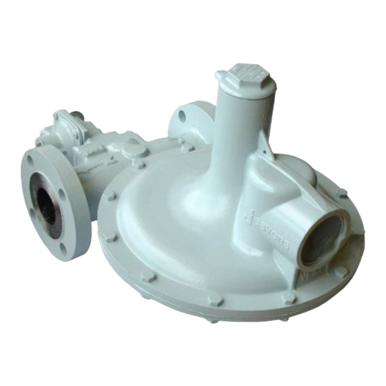
- Page 1 J125B Service Regulator Inlet Pressure up to 8.6 bar Commissioning Instructions General Arrangements Parts Lists Maintenance Instructions For: J125 MKII Regulator with balanced valve 1 ½”, 2” and 50mm size...
- Page 2 J125B: Commissioning Instructions FITTING REGULATOR INTO PIPEWORK • Ensure that this product is suitable for the chosen application. • Installation, adjustment and maintenance by authorised, trained personnel only. • When being fitted to an appliance, refer to the appliance manufacturers instructions.
- Page 3 J125B: Commissioning Instructions 4. If safety shut-off device is fitted unscrew reset spindle end cap and firmly pull. Hold in this position until the outlet pipework is fully pressurised, then release reset spindle end cap gently. See Fig. 5. 5. Re-screw reset spindle end cap into body, ensuring not to jam reset spindle.
- Page 4 J125B: Commissioning Instructions 17. Re-cock OPSS device by unscrewing reset spindle end cap and firmly pull. Hold in this position until the outlet pipework is fully pressurised, then release reset spindle end cap gently. Re-screw reset spindle end cap into body. See Fig. 9.
- Page 5 J125B: Commissioning Instructions IF THE REQUIRED REGULATOR OUTLET PRESSURE CANNOT BE ACHIEVED WITH THE SPRING FITTED 31. Remove top cap from regulator cover. 32. Choose a loading spring from catalogue or page 17 that will give the required outlet pressure range.
- Page 6 J125B: Commissioning Instructions 49. Remove bottom spring holder and UPSS top spring holder. 50. Remove UPSS spring and replace with new one. See Fig. 13. 51. Replace UPSS spring holder, ensuring that spigot locates in UPSS spring. 52. Replace bottom spring holder locating three webs into slots in bottom of cover, ensuring not to disturb UPSS spring and UPSS spring holder.
- Page 7 J125B: General Arrangement S1, S2, S3 Assembly – Fig 14 DIAPHRAGM CASE ASSEMBLY SEE FIG. 17 S2 VERSION (FULL CAPACITY RELIEF VALVE) S1 VERSION S3 VERSION (NO RELIEF VALVE) (LIMITED RELIEF VALVE)
- Page 8 J125B: General Arrangement S4, S5, S10 Assembly- Fig 15 DIAPHRAGM CASE ASSEMBLY SEE FIG. 17 OPSS SAFETY SHUT OFF ASSEMBLY SEE FIG. 18 S4 VERSION (FULL CAPACITY RELIEF VALVE) S10 VERSION S5 VERSION (NO RELIEF VALVE) (LIMITED RELIEF VALVE)
- Page 9 J125B: General Arrangement S6, S7, S8, S9, S11, S12 Assembly- Fig 16 DIAPHRAGM CASE ASSEMBLY SEE FIG. 17 OPSS/UPSS SAFETY SHUT OFF ASSEMBLY SEE FIG. 19 S8 VERSION (FULL CAPACITY RELIEF VALVE) S6, S7 & S11 VERSIONS UPSS ONLY SEE FIG. 20 S11 &...
- Page 10 J125B: General Arrangement Diaphragm Case Assembly – Fig 17 S2, S4, S6 & S8 VERSIONS (FULL RELIEF VALVE) S1, S10, S11 & S12 S3, S5, S7 & S9 VERSIONS VERSIONS (NO RELIEF VALVE) (LIMITED RELIEF VALVE)
- Page 11 J125B: General Arrangement OPSS Safety Shut Off Assembly – Fig 18 TOP COVER TO BODY OPSS BODY TO FIXING ADAPTOR PLATE ENLARGED VIEW OF FIXING VALVE DISC...
- Page 12 J125B: General Arrangement OPSS/UPSS Safety Shut Off Assembly – Fig 19 TOP COVER TO BODY OPSS BODY TO FIXING ADAPTOR PLATE ENLARGED VIEW OF FIXING VALVE DISC...
- Page 13 J125B: General Arrangement UPSS Safety Shut Off Assembly – Fig 20 TOP COVER TO BODY OPSS BODY TO FIXING ADAPTOR PLATE ENLARGED VIEW OF FIXING VALVE DISC...
-
Page 14: Loading Spring
J125B: Parts List ITEM DESCRIPTION PART NUMBER No. Off TOP CAP I70103P001 "O" RING (TOP CAP) JOBS133 ADJUSTMENT SCREW I73183P001 ROD STOP I73056P001 FLANGE STOP ROD I73174P001 SPRING ADJUSTING NUT (Full Relief) I71533P001 LOADING SPRING SEE TABLE RELIEF VALVE SPRING... - Page 15 J125B: Parts List Continued ITEM DESCRIPTION PART NUMBER No. Off SPRING GUIDE I72272P001 DIAPHRAGM PLATE (No / Limited Relief) I70012P052 DIAPHRAGM (No / Limited Relief) J12509-115 RELIEF VALVE CUP I73054P002 SCREWED BODY 1½" J12508-080 + SCREWED BODY 2" J12509-080 +...
- Page 16 J125B: Parts List Continued ITEM DESCRIPTION PART NUMBER No. Off CIRCLIP VALVE SPINDLE JCIR1500-015B VALVE DISC (Moulded) J12509-109M VALVE SPRING CUP J12506-251 "O" RING (Safety Shut off /Adaptor Plate) JORM0276-24D CIRCLIP (Front "O" Ring Washer) JCIR2000K-17B SAFETY SHUT OFF BODY J12506-239 + FRONT "O"...
- Page 17 NOTE: A minimum differential of 30mb must be maintained between OPSS and UPSS set pressures SPARES KITS REGULATOR TYPE SPARES KIT PART NUMBER J125B-S1 & S3 SK2529-08 J125B-S2 SK2529-09 J125B-S4, S6 & S8 SK2529-10 J125B-S5, S7, S9, S10, S11 & S12 SK2529-11...
- Page 18 J125B: Maintenance Instructions Regulator Body Drawing Reference: Figs. 14, 15 & 16 NOTE: Numbers in brackets identify items on drawings Regulator Dismantling Procedure. 1. Check external surfaces for excessive corrosion. 2. Disconnect diaphragm case assembly from regulator body (38) by removing the three grub screws (16), gently pull out the case from the regulator body (38).
- Page 19 J125B: Maintenance Instructions Diaphragm Case Drawing Reference: Figs. 17 NOTE: Numbers in brackets identify items on drawings Diaphragm Case Dismantling Procedure Unscrew top cap (1) and remove "O" ring (2). Unscrew and remove adjusting screw (3) and loading spring (7).
- Page 20 J125B: Maintenance Instructions Diaphragm Case, Continued Diaphragm Case Rebuilding Procedure continued.. 5. Replace flat washer (11) over cap screw (33). 6. Screw diaphragm stem (20) onto cap screw (33) securing diaphragm assembly For No Relief version go to instruction 14.
- Page 21 J125B: Maintenance Instructions Safety Shut Off Units Drawing Reference: Figs. 18, 19 & 20 NOTE: Numbers in brackets identify items on drawings Safety Shut-off Dismantling Procedures. Unscrew top cap (55) and remove "O" ring (53). 2. Unscrew and remove top spring holder (52) together with OPSS spring (57), or UPSS spacer tube (93).
- Page 22 J125: Maintenance Instructions Safety Shut Off Units - Continued Safety Shut-off Rebuilding Procedures. NOTE: Inspect all sealing "O" rings, diaphragms and gaskets and replace where necessary (a soft spares kit is available for this purpose see page 16). The use of Molykote 111 "O" ring lubricant is recommended during the rebuild- unless for use with oxygen when no lubricant should be used.
- Page 23 J125: Maintenance Instructions Safety Shut Off Units - Continued Safety Shut-off Rebuilding Procedures – Continued 19. Replace bottom spring holder (54) together with UPSS screw (56) if fitted, into chimney of top cover (60) by aligning ribs of bottom spring holder (54) with slots in top cover (60). 20.
- Page 24 Elster Jeavons is committed to a programme of continuous quality enhancement. All equipment designed by Elster Jeavons and manufactured within the Elster-Instromet Group benefits from the groups quality assurance standards, which are approved to EN ISO9001:2008. Elster Jeavons has a programme of continuous product development and improvement and in consequence the information in this leaflet may be subject to change or modification without notice.
Need help?
Do you have a question about the J125B and is the answer not in the manual?
Questions and answers