
Related Manuals for Eaton Pow-R-Line 3FQS


Summary of Contents for Eaton Pow-R-Line 3FQS
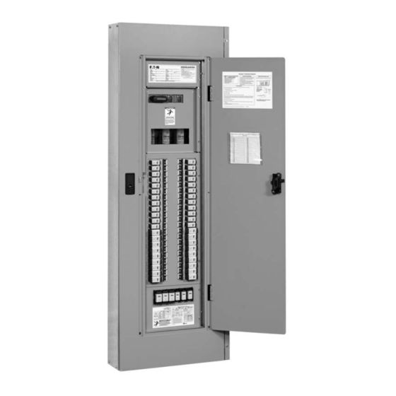
- Page 1 Pow-R-Line ® 3FQS Read and retain for Fusible Panelboard future reference Instruction Leaflet E3A1071 RevG...
-
Page 2: Table Of Contents
ABLE OF ONTENTS Section Page Danger and warnings for installation of the equipment ... . .3-4 Enclosure mounting instructions .......5 Neutral bonding wire installation (SERVICE equipment) . -
Page 3: Danger And Warnings For Installation Of The Equipment
For the latest version of this Instruction Leaflet, download "Instruction Leaflet" from the Eaton website at: www.Eaton.com. - Page 4 Signal Words The signal words “DANGER,” “WARNING,” “CAUTION” and “NOTICE” (along with their assigned symbol) throughout this manual indicate the degree of hazard the user may encounter. These symbols and words are defined as: DANGER: Indicates a hazardous situation which, if not avoided, will result in death or serious injury.
-
Page 5: Enclosure Mounting Instructions
NCLOSURE OUNTING NSTRUCTIONS I I m m p p o o r r t t a a n n t t : : Read these instructions carefully to assure proper installation and assembly. Ensure all fasteners and connections are properly tightened (refer to torque information label E3A1064 on panelboard) A separate booklet NEMA Standards Publication ANSI/NEMA PB 1.1-2007 titled “... -
Page 6: Neutral Bonding Wire Installation (Service Equipment)
EUTRAL ONDING NSTALLATION For SERVICE entrance installations, install bonding wire between the neutral bar stud using -20 hex flange nut and enclosure using #10-32 x ” long screw, as shown in the illustration below, and tighten fasteners to specified torque values. 400A Neutral Bar 200A Neutral Bar 800A Neutral Bar... -
Page 7: Ccpb Branch Disconnect Installation & Removal
CCPB B RANCH ISCONNECT NSTALLATION AND EMOVAL NSTRUCTIONS Electrical Shock Hazard Electrical equipment may contain hazardous voltages. These can cause electrical shock, burn or death. Only qualified personnel should perform procedures involving electrical equipment. Always properly ground equipment and lockout electric power (de-energize) before accessing electrical equipment and enclosures. -
Page 8: Branch Circuit Deadfront Knockout Removal
Loosen and remove #10-32 x 1/4” screw Slide CCPB out until “T” slot clears branch sub-assembly and remove Removing CCPB Branch Disconnect 1. De-energize and lockout panelboard power supply. 2. Push CCPB switch to the “OFF” (O) position and remove fuse (if present). 3. -
Page 9: Fuse Replacement
EPLACEMENT 1. Prior to replacing any open fuse, follow safe work practices*. 2. Locate open fuse indicated by indicating lamp** or open fuse indication on CUBEFuse ® (if equipped). 3. Turn switch to the “OFF” (O) position. 4. Lockout/tagout CCPB per OSHA requirements. 5. -
Page 10: Typical Wiring
YPICAL IRING Additional information is contained on Voltages and System Types panelboard labels: Volts AC Volts DC Phase Wires _ < 125 • 3A1063; Main Label - specific panel ratings 240/120 4 Delta • 3A1064; Agency Label - wire sizes & ratings, 208Y/120 fastener torque values, assembly short-circuit 480Y/277... -
Page 11: Typical Coordination Panelboard Schematics
YPICAL OORDINATION ANELBOARD CHEMATICS See rating of main fused disconnect switch, if used. Single-Phase, 2 Wire Single-Phase, 2 Wire Single-Phase, 2 Wire Non-Fused Disconnect Main Lug Only Fused Disconnect Single-Phase, 3 Wire Single-Phase, 3 Wire Single-Phase, 3 Wire Main Lug Only Fused Main Disconnect Non-Fused Main Disconnect Three-Phase, 3 Wire... -
Page 12: Coordination Panelboard Replacement Parts
OORDINATION ANELBOARD EPLACEMENT ARTS See list for part numbers. Selectable Knockout Endwall Selectable Blank Endwall A & B - Main Devices and Lugs * Also for use as feed-through lugs based upon panelboard ampacity rating 2A1909-1* Kit, compression lug 3-phase, 70-200A 2A1909-2* Kit, mechanical lug 3-phase, 70-200A 2A1909-3* Kit, double/sub-feed lug 3-phase, 30-200A 2A1909-4... - Page 13 2A1909-18* Kit, mechanical lug 1-phase, 2 wire, 30-60A 2A1909-19 Kit, main disconnect 30-60A 1-phase, 2 wire, 2A1909-20* Kit, compression lug 3-phase, 225-400A 2A1909-21* Kit, mechanical lug 3-phase, 225-400A 2A1909-22* Kit, double/sub-feed lug 3-phase, 225-400A 2A1909-23* Kit, compression lug 1-phase, 3 wire, 225-400A 2A1909-24* Kit, mechanical lug 1-phase, 3 wire, 225-400A 2A1909-25* Kit, double/sub-feed lug 1-phase, 3 wire, 225-400A 2A1909-26* Kit, compression lug 1-phase, 2 wire, 225-400A...
-
Page 14: Replacement Parts
CCPB B RANCH ISCONNECTS AND CUBEF ® EPLACEMENT ARTS I - CCPB Branch Disconnects P P o o l l e e s s A A m m p p a a c c i i t t y y P P a a r r t t N N u u m m b b e e r r 1-Pole CCPB-1-(amp)CF... -
Page 15: Notes
OTES E3A1071 RevG... - Page 16 Eaton Corporation Electrical Sector 1111 Superior Ave. Cleveland, OH 44114 United States 877-ETN-CARE Eaton.com ©2010 Eaton Corporation All Rights Reserved Printed in USA Publication No. E3A1071 RevG December 2010 E3A1071 RevG...
Need help?
Do you have a question about the Pow-R-Line 3FQS and is the answer not in the manual?
Questions and answers