Table of Contents
Advertisement
Advertisement
Table of Contents

Related Manuals for ESAB PT-36


Summary of Contents for ESAB PT-36
- Page 1 PT-36 Mechanized Plasmarc Cutting Torch Instruction Manual (EN) 0558005239...
- Page 2 BE surE thIs INforMatIoN rEachEs thE opErator. You caN gEt Extra copIEs through Your supplIEr. cautIoN these INstructIoNs are for experienced operators. If you are not fully familiar with the principles of operation and safe practices for arc welding and cutting equipment, we urge you to read our booklet, “precautions and safe practices for arc Welding, cutting, and gouging,”...
-
Page 3: Table Of Contents
2.5 PT-36 Technical Specifications........ - Page 4 taBlE of coNtENts...
-
Page 5: Safety Precautions
Users of ESAB welding and plasma cutting equipment have the ultimate responsibility for ensuring that anyone who works on or near the equipment observes all the relevant safety precautions. Safety precautions must meet the requirements that apply to this type of welding or plasma cutting equipment. The following recommendations should be observed in addition to the standard regulations that apply to the workplace. - Page 6 sEctIoN 1 safEtY prEcautIoNs WElDINg aND plasMa cuttINg caN BE INJurIous to YoursElf WarNINg aND othErs. taKE prEcautIoNs WhEN WElDINg or cuttINg. asK for Your EMploYEr’s safEtY practIcEs WhIch shoulD BE BasED oN MaNufacturErs’ haZarD Data. ElEctrIc shocK - Can kill. - Install and earth (ground) the welding or plasma cutting unit in accordance with applicable standards.
-
Page 7: Description
DEscrIptIoN 2.1 general The PT-36 Mechanized Plasmarc Cutting Torch is a plasma arc torch factory assembled to provide torch compo- nent concentricity and consistent cutting accuracy. For this reason, the torch body can not be rebuilt in the field. Only the torch front-end has replaceable parts. -
Page 8: Optional Accessories
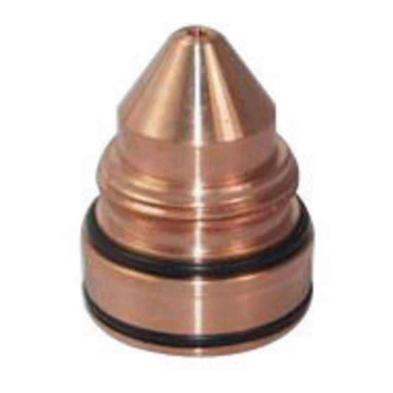
PT-36 Plasmarc Cutting Torch to be used underwater with slight sacrifice of cut quality. This system also permits operation above water as the flow of water through the muffler reduces fume, noise, and arc U.V. - Page 9 2 DEscrIptIoN pt-36 200a start-up Kit ....................0558005222 part Number Quantity Description 0558003914 Electrode O2 UltraLife, Standard 0558003928 Electrode N2/H35, Standard 0558005459 Electrode O2/N2, Low Current 0558006010 Nozzle PT-36 1.0mm (.040") 0558006014 Nozzle PT-36 1.4mm (.055") 0558006020 Nozzle PT-36 2.0mm (.080") 0558006130 Shield PT-36 3.0mm (.120")
- Page 10 0558007624 Shield PT-36 2.4mm (.095") 0558006908 Nozzle PT-36 0.8mm (.030") 0558006018 Nozzle PT-36 1.8mm (.070") 0558006030 Nozzle PT-36 3.0mm (.120") pt-36 h35 heavy plate start-up Kit ................0558005225 part Number Quantity Description 0558003963 Electrode, Tungsten 3/16"D 0558003965 Nozzle H35 .198" Divergent 0558003964 Collet 3/16"D Electrode...
-
Page 11: Pt-36 Technical Specifications
Maximum safe gas pressures at Inlets to torch: 125 psig (8.6 bars) safety Interlocks: This torch is intended for use with ESAB Plasmarc cutting systems and controls employing a water flow switch on the coolant return line from the torch. Removal of the nozzle retaining cup to service the torch breaks the... - Page 12 sEctIoN 2 DEscrIptIoN...
-
Page 13: Installation
3.1.1 connection to the arc starter Box The PT-36 has two water cooled power cables which must be connected to the negative output from the power supply. The right handed 7/16-20 fitting is on the cable supplying coolant to the torch. The left handed 7/16-20 fitting is on the cable returning coolant from the torch. -
Page 14: Mounting Torch To Machine
sEctIoN 3 INstallatIoN 3.1.2 connection of gas hoses 1 - Female old-style air water nut for Shield Gas connec- tion. 2 - B-IG fittings for Plasma Start gas and Plasma Cut gas. Either hose can be attached in either location. Mounting torch to Machine Refer to machine manual. -
Page 15: Operation
sEctIoN 4 opEratIoN oil and grease can Burn Violently! • Never use oil or grease on this torch. WarNINg • Handle torch clean hands only on clean surface. • Use silicone lubricant only where directed. • Oil and grease are easily ignited and burn violently in the presence of oxygen under pressure. - Page 16 sEctIoN 4 opEratIoN ExplosIoN haZarD. ceRtAIN mOlteN AlUmINUm-lItHIUm (al-li) AllOys cAN cAUse WarNINg ExplosIoNs WhEN plasMa cut WIth WatEr. Do Not plasMa cut thE folloWINg al-li alloYs WIth WatEr: AlItHlIte (AlcOA) x8192 (AlcOA) AlItHAlly (AlcOA) NAvAlIte (Us NAvy) 2090 AllOy (AlcOA) lOckAlIte (lOckHeeD) x8090A (AlcOA) kAlIte (kAIseR)
-
Page 17: Cut Quality
sEctIoN 4 opEratIoN oil and grease can Burn Violently! • Never use oil or grease on this torch. • Handle torch clean hands only WarNINg on clean surface. • Use silicone lubricant only where directed. • Oil and grease are easily ignited and burn violently in the presence of oxygen under pressure. - Page 18 sEctIoN 4 opEratIoN Before attempting aNY corrections, check cutting variables with the cautIoN factory recommended settings/consumable part numbers listed in process Data. 4.2.2. cut angle Negative cut angle Top dimension is greater than the bottom. • Misaligned torch • Bent or warped material Part •...
- Page 19 sEctIoN 4 opEratIoN 4.2.3. cut flatness Top And Bottom Rounded. Condition usually occurs when material is .25" thick (6,4mm) or less. • High current for given material thickness (See Pro- cess Data for proper settings). Drop Part Top Edge Undercut •...
- Page 20 sEctIoN 4 opEratIoN 4.2.4. surface finish process Induced roughness Cut face is consistently rough. May or may not be confined to Top View one axis. • Incorrect Shield Gas mixture (See Process Data). Cut Face • Worn or damaged consumables. Machine Induced roughness Can be difficult to distinguish from Process Induced Roughness.
- Page 21 sEctIoN 4 opEratIoN recommended cutting speed and arc voltage will give optimal cut- ting performance in most cases. smallincremental adjustments may cautIoN be needed due to material quality, material temperature and specific alloy. the operator should remember that all cutting variables are in- terdependent.
-
Page 22: Torch Flow Passages
sEctIoN 4 opEratIoN torch flow passages plasma gas in shield gas in water in water out View showing gas passages View showing water passages... -
Page 23: Maintenance
Wear on torch parts is a normal occurrence to plasma cutting. Starting a plasma arc is an erosive process to both the electrode and nozzle. Regularly scheduled inspection and replacement of PT-36 parts must take place to maintain cut quality and consistent part size. -
Page 24: Torch Front End Disassembly
sEctIoN 5 MaINtENaNcE torch front End Disassembly hot torch WIll BurN sKIN! DaNgEr alloW torch to cool BEforE sErVIcINg. 1. Remove shield retainer. NotE: If the shield retainer is difficult to remove, try to screw the nozzle retainer tighter to relieve pressure on the shield. - Page 25 sEctIoN 5 MaINtENaNcE Incorrect assembly of the diffuser in the shield will prevent the torch cautIoN from working properly. Diffuser notches must be mounted away from the shield as illustrated. 4. Unscrew nozzle retainer and pull nozzle straight out of torch body. Inspect insulator portion of the nozzle retainer for cracks or chipping.
- Page 26 sEctIoN 5 MaINtENaNcE 7. Remove electrode holder from torch body. Hex on the end of the electrode holder removal tool will engage in a hex in the holder. Removal Gas Baffle Tool Electrode Holder Assembly Electrode NotE: The electrode holder is manufactured in two pieces. Do not disassemble. If the holder is damaged, re- place the electrode holder assembly.
-
Page 27: Torch Front End Disassembly (For Production Thick Plate)
sEctIoN 5 MaINtENaNcE torch front End Disassembly (for production thick plate) hot torch WIll BurN sKIN! DaNgEr alloW torch to cool BEforE sErVIcINg. 1. Remove the Shield Cup Retainer. NotE: If the shield cup retainer is difficult to remove, try to screw the nozzle retaining cup tighter to relieve pres- sure on the shield cup retainer. - Page 28 sEctIoN 5 MaINtENaNcE 4. Unscrew nozzle retainer and pull nozzle straight out of torch body. Inspect insulator portion of the nozzle retainer for cracks or chipping. Replace if damaged. Inspect nozzle for: • melting or excessive current trans- fer. Nozzle Retaining Cup •...
- Page 29 sEctIoN 5 MaINtENaNcE 7. Remove electrode holder from torch body. Hex on the end of the electrode holder removal tool will engage in a hex in the holder. Torch Body Electrode Holder Removal Tool 8. Disassemble electrode holder and gas baffle. Carefully remove O-ring from electrode holder and slide baffle from holder.
-
Page 30: Assembly Of Torch Front End
sEctIoN 5 MaINtENaNcE assembly of torch front End over tightened parts Will Be Difficult to Disassemble and May Dam- age torch. Do not over tighten parts during reassembly. threaded cautIoN parts are designed to work properly when hand tightened, approxi- mately 40 to 60 inch/pounds. -
Page 31: Assembly Of Torch Front End (For Production Thick Plate)
sEctIoN 5 MaINtENaNcE assembly of torch front End (for production thick plate) over tightened parts will be difficult to disassemble and may dam- age torch. Do not over tighten parts during reassembly. threaded cautIoN parts are designed to work properly when hand tightened, approxi- mately 40 to 60 inch/pounds. - Page 32 sEctIoN 5 MaINtENaNcE 3. Screw electrode assembly in a clockwise direction to torch body. Electrode will tighten in the correct position when collet closes. Nozzle Retaining Cup Torch Body Nozzle NotE: When assembling, place the nozzle inside the nozzle retaining cup and thread the retainer/nozzle com- bination on the torch body.
-
Page 33: Torch Body
sEctIoN 5 MaINtENaNcE torch Body • Inspect O-rings daily and replace if damaged or worn. • Apply a thin coat of silicone grease to O-rings before assembling torch. This facilitates easy future as- sembly and disassembly for service. • O-ring (1.61 I.D. X .070 BUNA-70A). ElEctrIc shocK caN KIll! WarNINg BEforE pErforMINg torch MaINtENaNcE:... -
Page 34: Removal And Replacement Of The Torch Body
sEctIoN 5 MaINtENaNcE removal and replacement of the torch Body ElEctrIc shocK caN KIll! BEforE pErforMINg torch MaINtENaNcE: WarNINg • Turn power switch of the power source console to the OFF position • Disconnect primary input power. 1. Loosen the worm gear hose clamp so that the torch sleeving can be freed and pulled back up the cable bundle. - Page 35 sEctIoN 5 MaINtENaNcE 2. Unscrew the gas hoses and power cables from the torch head assembly by using a 7/16" (11.1mm) and a 1/2" (12.7mm) wrench. Disconnect the power cables which are threaded onto the shorter stems at the back of the torch.
- Page 36 sEctIoN 5 MaINtENaNcE 4. To install the new torch head assembly - Connect the pilot arc cable and the main power cable by reversing the steps taken to disconnect them. Be sure the gas and water fittings are tight enough to prevent leaks, but do not use any kind of sealant on them.
-
Page 37: Reduced Consumable Life
Increasing likelihood that the plate will spring up against the nozzle causing a double arc. This can be mitigated by careful operator attention and by increasing standoff and reducing cutting speeds. If possible, use an OXWELD torch for skeleton cutting or operate the PT-36 at a high standoff. height control problems •... - Page 38 sEctIoN 5 MaINtENaNcE checking for coolant leaks: Coolant leaks can originate from seals on the electrode, electrode holder, nozzle, and torch body. Leaks could also originate from a crack in the insulating material of the torch or nozzle retaining cup or from a power cable. To check for leaks from any source remove the shield cup, clean off the torch, purge it, and place it over a clean dry plate.
- Page 39 sEctIoN 5 MaINtENaNcE...
- Page 40 sEctIoN 5 MaINtENaNcE problem: failure to start START Is there an error message? Address system error Fixed ? Change nozzle Done consumables Fixed ? Done worn out? and electrode Troubleshoot Try to fire Will control & arc Was there you cutting arc transfer torch in air a pilot arc?
- Page 41 sEctIoN 5 MaINtENaNcE problem: failure to start Done Install shield retainer, air Fixed ? Fixed ? curtain p/n 0558004616 Set shield gas correctly. Try higher flows if necessary. Done Using shield gas plastic set correctly? shield retainer? Set p.a. to Is p.a.
- Page 42 sEctIoN 5 MaINtENaNcE...
Need help?
Do you have a question about the PT-36 and is the answer not in the manual?
Questions and answers