
Related Manuals for ESAB CROSSBOW


Summary of Contents for ESAB CROSSBOW
- Page 1 CROSSBOW Portable CNC Cutting Machine Instruction Manual Article Number 0560951719 Revision Date: September 29, 2014 Revision Number: B Language: ENG...
- Page 3 ESAB’s responsibilities and limitations on liability. Information in this document is subject to change without notice. This manual is for the convenience and use of the cutting machine purchaser. It is not a contract or any obligation on the part of ESAB Cutting Systems.
-
Page 4: Table Of Contents
ESAB Cutting Systems Table of Contents 1 Safety ....................11 1.1 Introduction ......................11 1.2 Safety Hazards and Warnings ................11 1.3 Electrical Grounding ...................16 1.4 Service Precautions ...................16 1.5 Recommended Safety References ..............17 1.5.1 International ................... 17 1.5.2 United States ..................18 1.5.3 Canada .................... - Page 5 ESAB Cutting Systems 3.4.4 Install Initial Height Sensing Cable ............56 3.4.5 Connect Power and Air to Plasma Unit ........... 57 3.5 Initial Power-Up Testing ..................58 3.6 Switching Between Metric and Inch ..............59 4 Operation ..................61 4.1 Control Panel and Function ................61 4.2 CNC System Features ..................
- Page 6 ESAB Cutting Systems 4.11.6 【F6】MORE ..................77 4.11.7 【F7】RETURN ..................77 4.12 Auto Mode MORE Window (2 Level) Functions ..........78 4.12.1 【F1】OUTLINE Function ..............78 4.12.2 【F2】WENTAI ..................79 4.12.3 【F3】ROTATE (Program Rotation) ............79 4.12.4 【F4】MIRROR ..................80 4.12.5 【F5】SCALE ..................80 4.12.6 【F6】NEST ..................
- Page 7 ESAB Cutting Systems 4.20.3 【F3】MORE ..................96 4.20.4 【F4】MACH-0 (Clear Machine Coordinates) ......... 96 4.20.5 【F5】RAPID (Rapid Jog Speed) ............96 4.20.6 【F6】PROG-0 (Clear Program Coordinates) ........96 4.20.7 【F7】RETURN ..................97 4.21 Manual Mode MORE Window (2 Level) Functions ........98 4.21.1 【F3】REC PT1 and【F4】REC PT2 (Plate Alignment) ......
- Page 8 ESAB Cutting Systems 4.26.6 【F6】APPLY ..................118 4.27 Part Programming Instructions ................. 119 4.27.1 File Format ....................119 4.27.2 Program Names ..................119 4.27.3 Program Format ..................119 4.27.4 Units Of Measurement ................120 4.27.5 Programming Mode ................120 4.27.6 Axis Orientation ..................120 4.27.7 G-Codes ....................121 4.27.8 M-Codes ....................127...
- Page 9 ESAB Cutting Systems 5.6.14 Adjusting Rail Axis Drive Pinion Engagement ........160 5.6.15 Adjusting Cross Beam Drive Pinion Engagement........161 5.6.16 Adjusting the V-Wheels ................. 162 5.6.17 Replacing Drive Motor ................164 5.6.18 Replacing Drive Pinions ................ 165 5.6.19 Replacing V-Wheels ................166 5.6.20 Replacing the Solenoid Valve ...............
- Page 10 ESAB Cutting Systems Shape 9: RING......................199 Shape 10: OCTAGON ..................... 200 Shape 11: TAB RECTANGLE ................. 201 Shape 12: CUTOUT ....................202 Shape 13: LINE CUT ....................203 Shape 14: ARC SECTOR ..................204 Shape 15: HOLE CUTOUT ..................205 Shape 16: RECT.
-
Page 11: Safety
Safety Introduction ESAB cutting machines are designed to operate both safely and effectively. Sensible attention to operating procedures, precautions, and safe practices is required to achieve a full measure of usefulness. Whether an individual is involved with operation, servicing, or as an observer, compliance with established precautions is mandatory. - Page 12 ESAB Cutting Systems envelope of equipment. • Follow lockout-tagout procedures before servicing to prevent inadvertent startup. • Stay clear of rails and cutting table during operation. • Keep hands clear of moving components. FLYING DEBRIS HAZARD. Hot spatter can burn and injure eyes.
- Page 13 ESAB Cutting Systems • Wear dark safety glasses or goggles with side shields. Replace glasses/goggles when lenses are pitted or broken. • Warn others not to look directly at the arc unless wearing appropriate safety glasses. • Prepare cutting area to reduce reflection and transmission of ultraviolet light.
- Page 14 ESAB Cutting Systems • Do NOT use water injection plasma torches. • Contact your aluminum supplier for additional safety information regarding hazards associated with these alloys. EXPLOSION AND FIRE HAZARD. Ordinary materials can explode and burn in the presence of oxygen.
- Page 15 ESAB Cutting Systems TOXIC FUME HAZARD. Hexavalent Chromium Cr(VI) is a toxic chemical within fumes. It is created in a variety of processes, including plasma cutting of stainless steel. If you plasma cut stainless steel, you will need to comply with the following to protect your employees from Cr(VI) exposure.
-
Page 16: Electrical Grounding
ESAB Cutting Systems Electrical Grounding Electrical grounding is required for proper SAFETY and equipment operation. Refer to installation section for detailed grounding instructions. ELECTRICAL SHOCK HAZARD. Improper grounding can cause system damage, severe injury or death. Plasma system must be properly grounded to the cutting table. -
Page 17: Recommended Safety References
ESAB Cutting Systems Recommended Safety References The following publications on welding and cutting safety are recommended for your review. These publications have been prepared to prevent personnel injury and property damage, resulting from unsafe practices. Although some sources are not related specifically to industrial cutting systems, the principles of safety apply equally. -
Page 18: United States
ESAB Cutting Systems 1.5.2 United States ANSI • ANSI Z49.1 Safety in Welding and Cutting American Welding Society • AWS C5.1 Recommended Practices for Plasma Arc Welding • AWS C5.10/C5.10M:2003 Recommended Practices for Shielded Gases for Welding and Plasma Arc Cutting. -
Page 19: Canada
Form 2035 Precautions and Safe Practices in Welding and Cutting with Oxygen-Fuel Gas Equipment - ESAB Cutting Systems. • Form F52-529 Precautions and Safe Practices for Plasma Welding and Cutting - ESAB Cutting Systems. • Form 3499 Safety Precautions for Oxygen, Nitrogen, Argon, Helium, Carbon Dioxide, Hydrogen, and Acetylene - ESAB Cutting Systems. - Page 20 ESAB Cutting Systems CROSSBOW Page 20...
-
Page 21: Description
The Crossbow CNC is simple and easy to learn. It can be manually programmed, it can generate its own program from a library of common shapes, or programs can be loaded through a USB port from an off-line programming software. -
Page 22: Machine Components
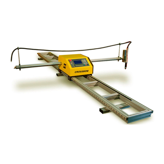
ESAB Cutting Systems Machine Components The Crossbow consists of a Central Unit with CNC, Rail Track assembly with Stabilizer Feet, Cross Beam with gas tubes, Torch Lifter, and Cable Holders, as shown below. Optionally, the machine may be equipped with an oxy-fuel torch or a plasma torch. If the machine is purchased with both oxy-fuel and plasma torches, one torch must be removed in order to install and use the other. -
Page 23: Machine Dimensions
ESAB Cutting Systems Machine Dimensions Figure 2: Crossbow Dimensions Overall Track Length 2200 or 4000 mm (86 or 157 in.) Cross Beam Width 2362 mm (93 in.) Effective cutting length 1220 or 3100 mm (4 ft. or 10 ft.) Effective cutting width 1525 mm (5 ft.) -
Page 24: Machine Specifications
• The Crossbow may be supplied with or without an oxy-fuel torch. If supplied with a torch, it may be supplied with the Oxweld C-69 torch for use with any fuel gas other than Acetylene, or it may be supplied with the Oxweld C-70 torch for use with Acetylene only. -
Page 25: Axis Orientation
Motion away from the operator, front-to-back, is Y plus (+Y) direction. • Motion towards the operator, back-to-front, is Y Minus (-Y) direction. Please Note: This axis orientation is rotated 90 degrees clockwise from ESAB’s standard axes orientation. Figure 3: Axis Orientation... - Page 26 ESAB Cutting Systems CROSSBOW Page 26...
-
Page 27: Installation
ESAB Cutting Systems Installation Receiving Inspection Upon receiving the Crossbow machine, thoroughly inspect all crates and boxes for any signs of shipping damage. A claim must be filed with the shipping company immediately if any damage is found. Open the crates and boxes and inventory the items to make sure nothing is missing from the shipment. -
Page 28: Base Machine Setup
ESAB Cutting Systems Base Machine Setup 3.2.1 Prepare Rail Track Step 1 Invert Rail Track With the help of a second person, grasp the Rail Track assembly at each end and carefully turn it over and lay it on its back, avoiding damage to the drive rack. Set the track on pieces of wood to protect the drive rack from damage. - Page 29 ESAB Cutting Systems Step 2 Arrange T-Slot Nuts Locate the captive T-Slot Nuts in the frame and move them to the desired locations. Figure 5: T-Slot Nuts Number Description Frame Slots M8 Captive T-Slot Nuts CROSSBOW Page 29...
- Page 30 ESAB Cutting Systems Step 3 Attach Stabilizer Feet Attach the Stabilizer Feet to the bottom of the Rail Track assembly using the supplied M8 screws. Leave the screws loose until the three feet are attached and arranged in the desired location, then tighten.
- Page 31 ESAB Cutting Systems Step 4 Set Rail Track Upright With the help of a second person, turn rail track upright and set it on a stable, level surface, where the end of the Rail Track is easily accessible. Figure 7: Rail Track Assembled...
-
Page 32: Install Central Unit On Rail Track
ESAB Cutting Systems 3.2.2 Install Central Unit on Rail Track To avoid damaging the machine, this operation should be done by two-persons. The Central Unit weighs approximately 28 Kg (61 lbs.). Step 1 Lift and hold Central Unit One person must carefully lift and hold the Central Unit near the end of the rail, as shown below. Care must be taken to avoid bumping the Bearing Blocks into the ends of the Guide rails. - Page 33 ESAB Cutting Systems Step 2 Carefully guide Bearing Blocks onto Guide Rails A second person should carefully guide the Bearing Blocks onto the Guide Rail, as shown above. Once the first set of Bearing Blocks are completely on the Guide Rail, carefully move the unit further onto the Rail Track while holding it level.
- Page 34 ESAB Cutting Systems Step 3 Install Rubber Bumper/Stops The machine is supplied with two rubber bumpers, and a pair of M6x40mm Socket Head Cap Screws. Install one of these in the last bolt hole at each end of the rail to prevent the Central Unit from sliding off the end of the Rail Track.
-
Page 35: Install Cross Beam Assembly
ESAB Cutting Systems 3.2.3 Install Cross Beam Assembly Handle the Cross Beam assembly with care to avoid damage to the gas fittings, gas pipes, solenoid valve, and the electrical plugs. Step 1 Lift and hold Cross Beam Carefully lift the Cross Beam and hold it parallel to the floor and perpendicular to the heat-shield on the side of the Central Unit. - Page 36 ESAB Cutting Systems Step 2 Insert Cross Beam into Central Unit Carefully insert the Cross Beam into the Central Unit, pushing lightly as it fits between the V-Wheels. Continue to slowly push the Cross Beam through the Central Unit as it fits through the second set of V- Wheels, and then engages with the drive pinion.
- Page 37 ESAB Cutting Systems Step 4 Install First Cable Holder This step is only required if the machine will be using a plasma torch. It must be installed after the Cross Beam is inserted into the Central Unit, but before any hoses or cables are connected to the Cross Beam.
- Page 38 ESAB Cutting Systems Note: Only screw the Cable Clamps onto the Cable Holder Post until the top of the post is flush with the inside of the Cable Clamp. This will allow it to turn freely. After the plasma torch lead is installed it will prevent the Cable Clamp from coming unscrewed from the post.
-
Page 39: Install Torch Lifter
ESAB Cutting Systems 3.2.4 Install Torch Lifter Step 1 Mount Torch Holder to Motorized Lifter Insert the supplied M8 screw through the back of the Torch Lifter and into the Torch Holder then tighten. Make sure the Torch Holder is level, perpendicular to the Torch Lifter. - Page 40 ESAB Cutting Systems Step 2 Mount Motorized Lifter to Cross Beam Insert the supplied M8 screw through the hole in the mounting tang on the end of the Cross Beam, through the Joint Spacer, and into the threaded hole on the Torch Lifter mounting lug. Adjust the Torch Lifter until it is vertical and then tighten the screw.
- Page 41 ESAB Cutting Systems Step 3 Connect Lift Motor Cable Connect the 2-Pin Lift Motor cable connector between the Torch Lifter and the Cross Beam as shown below. Figure 17: Connecting Lift Motor Cable Number Description Torch Lifter Cross Beam Lift Motor Cable Connector...
- Page 42 ESAB Cutting Systems Step 4 Install Secondary Torch Holder This step is only required if the machine will be equipped with both oxy-fuel and plasma torches. The secondary torch holder is used to hold the torch that is not in use.
-
Page 43: Connect Cables
ESAB Cutting Systems 3.2.5 Connect Cables Step 1 Connect Lift Motor & Solenoid Valve Cable The Lift Motor & Solenoid Valve Cable is a 4-wire cable, with 4-pin connectors at each end. It connects between the back of the Central Unit and the end of the Cross Beam. - Page 44 ESAB Cutting Systems Connect other end to 4-pin socket at end of Cross Beam. Figure 21: Connecting Lift Motor & Solenoid Cable to Cross Beam Number Description 4-Pin Lift Motor & Solenoid Cable Socket Cross Beam (left-end) CROSSBOW Page 44...
- Page 45 ESAB Cutting Systems Step 2 Connect Input Power Cable The Input Power Cable is a standard 50 ft. cable with standard Edison connector (USA) on one end, and standard IEC power connection at the other end. Figure 22: Power Cable...
-
Page 46: Oxy-Fuel Torch Installation
ESAB Cutting Systems Oxy-fuel Torch Installation If the optional Oxy-Fuel torch was purchased, it must be assembled and installed into the torch holder. 3.3.1 Assemble Torch Assemble torch, needle valves, check valves, and torch hoses. Assemble the needle valves to the inlet fittings on the top of the torch, as shown. -
Page 47: Install Torch In Torch Holder With Adaptor
ESAB Cutting Systems 3.3.2 Install Torch in Torch Holder with Adaptor Use the supplied Torch Adaptor to install the Oxy-Fuel Torch into the Torch Holder, as shown. Arrange the torch so that the needle valves are easily accessible. Tighten the torch holder as necessary to hold the torch firmly in place. -
Page 48: Connect Torch Hoses
ESAB Cutting Systems 3.3.3 Connect Torch Hoses Connect the three torch hoses to the gas pipe fittings, as shown. Be sure to connect preheat oxygen and cutting oxygen hoses to the correct fittings. The Cutting Oxygen fitting is connected to outlet of solenoid valve. -
Page 49: Install Gas Supply Hoses
ESAB Cutting Systems 3.3.4 Install Gas Supply Hoses Attach the oxygen and fuel gas supply hoses to the inlet fittings on the Cross Beam, as shown. Figure 27: Connecting Gas Supply Hoses Number Description Fuel Gas Supply Hose, Part Number 0560949423... -
Page 50: Connect Gas Supplies
Oxygen Regulator (Customer Supplied, contact ESAB for part numbers) Oxygen Supply Hose, Part Number 0560949439 Oxygen Cylinder (Customer Supplied) Fuel Gas Regulator (Customer Supplied, contact ESAB for part numbers) Fuel Gas Supply Hose, Part Number 0560949423 Fuel Gas Cylinder (Customer Supplied) -
Page 51: Perform Leak Test
ESAB Cutting Systems 3.3.6 Perform Leak Test After installing and tightening all gas connections, perform a leak test to ensure there are no gas leaks anywhere in the system. 1) Pressurize gas supply lines to machine. 2) Close supply valve, unscrew regulator adjusting screws. -
Page 52: Plasma Torch Installation
ESAB Cutting Systems 3.4 Plasma Torch Installation 3.4.1 Install Second Cable Holder The Cable Holders hold the plasma torch lead and prevent it from pulling sideways on the torch while cutting. The Cable Holders are only required if a plasma torch is installed. If an oxy-fuel torch is also used, do not install the second Cable Holder until after the oxy-fuel torch hoses are installed. -
Page 53: Install Plasma Torch
ESAB Cutting Systems 3.4.2 Install Plasma Torch Have the torch fully assembled before inserting into the torch holder to prevent damage to the threads on the torch body. Assemble the PT-37 plasma torch with one of the Shields with IHS Lug. Insert the torch into the torch holder, rotating as necessary so the IHS Lug fits through the torch holder. -
Page 54: Install Plasma Interface Cable
Figure 31: Plasma Interface Cable Number Description 14-Pin Plasma Power Supply Connector (PowerCut and ESP-101) 6-Pin Crossbow Machine Connector Insert the 6-pin plug into the mating socked on the Connector Panel on rear of Central Unit. Figure 32: Connecting Plasma Interface Cable Number... - Page 55 ESAB Cutting Systems Connect the 14-pin plug into the matching socket at the ESAB Plasma Power Source. Figure 33: PowerCut Machine Interface Pigtail Figure 34: ESP-101Machine Interface Socket Number Description Plasma Power Supply 14-pin Plasma Interface Connector CROSSBOW Page 55...
-
Page 56: Install Initial Height Sensing Cable
Figure 35: IHS Cable Number Description 2-Pin Crossbow Machine Connector Ground Wire (Black) Torch Shield Wire (Red) Insert the 2-pin plug into the mating socked on the Connector Panel on rear of Central Unit. Figure 36: Connecting IHS Cable... -
Page 57: Connect Power And Air To Plasma Unit
ESAB Cutting Systems Connect the Red wire to the IHS Lug on the PT-37 Shield, as shown. Figure 37: IHS Cable Connected To Shield Cap Number Description Plasma IHS Cable PT-37 Torch Shield with IHS Lug Connect the Black wire to work ground. This wire must be electrically connected to the plate that is being cut. -
Page 58: Initial Power-Up Testing
ESAB Cutting Systems Initial Power-Up Testing First Power-Up Sequence: 1) Set Drive Engage/Disengage Switch to OFF position. 2) Make sure the E-Stop button is NOT pressed – turn clockwise to ensure it is released. 3) Turn on the main Power Switch on the rear of Central Unit. -
Page 59: Switching Between Metric And Inch
ESAB Cutting Systems Switching Between Metric and Inch The machine is set to “Metric” mode when delivered. If “Inch” mode is desired, follow this procedure: 1) From the Main Menu, press 【F4】to select SETUP. See section 4.25 for detailed information on the SETUP mode. - Page 60 ESAB Cutting Systems CROSSBOW Page 60...
-
Page 61: Operation
ESAB Cutting Systems Operation Control Panel and Function Figure 38: Central Unit Control Panel Number Description E‐Stop Button Display Input keys Drive Engage/Disengage Switch Drive Power Indicator Menu/Function keys Start Button Stop Button Software Update Button USB Port E-STOP (Emergency stop): Press to cut off all power to drives, torch lifter, and output relays. To restore power, turn the button clockwise until it pops out. -
Page 62: Cnc System Features
ESAB Cutting Systems CNC System Features • Controls both oxy-fuel and plasma cutting • Highly reliable and hardened against electrical noise from plasma, lightning, or power surges. • Advanced process functions, including corner speed control and automatic height control •... -
Page 63: Input Keys
ESAB Cutting Systems Input Keys Figure 40: Input Keys Number Description Program input keys Manual jog and feed rate control keys Process Control keys Start & Stop keys Input Keys Description Input Keys Usage Green key, start running. Red key, stop/pause running. - Page 64 The PIERCE key can be used to start a Pierce Cycle then continue cutting in the Auto Mode. Motion begins after the appropriate timer runs. These other process keys are not used on the Crossbow. Insert function in the Edit mode. Delete function in the Edit mode.
- Page 65 ESAB Cutting Systems In Auto Mode and Manual Mode this key is Station Up, and drives the motorized torch lifter upwards. In Shape Library or Program Editor this key is Page Up. In Auto Mode and Manual Mode this key is Station Down, and drives the motorized torch lifter downwards.
-
Page 66: Operational Overview - Oxy-Fuel Cutting
ESAB Cutting Systems Operational Overview – Oxy-Fuel Cutting Main steps for operating the Crossbow CNC with an Oxy-Fuel torch. 1. Use a CAD software program to create a DWG/DXF file, then use FastCAM to post and nest the files. 2. Use a USB memory stick to transfer the TXT file into the CNC. -
Page 67: Home Screen And Main Menu
Create or modify programs in an editor, read-in programs from USB [F4] SETUP Set system parameters, speeds, select plasma or oxy-fuel operation [F5] DIAGNOSE Displays input & output status (not used on Crossbow) [F6] LIBRARY Create parts or nests from the Shape Library CROSSBOW Page 67... -
Page 68: Main Menu Map
ESAB Cutting Systems Main Menu Map The CNC operates using a simple menu hierarchy. Below is the menu map for the main menus used by the operator. Each of these functions and the subsequent menus are discussed in more detail in the following sections. -
Page 69: Auto Mode Menu
ESAB Cutting Systems 4.9.2 Auto Mode Menu AUTO MANUAL EDIT SETUP DIAGNOSE LIBRARY SKIPTO MANUAL RESUME PREVIEW KERF MORE RETURN Return to Zero Point Menu Level (More functions) Adjust Kerf Width Graphical Preview of loaded program Resume a Parked Program... -
Page 70: Manual Mode Menu
ESAB Cutting Systems 4.9.3 Manual Mode Menu AUTO MANUAL EDIT SETUP DIAGNOSE LIBRARY AUTO STEP MORE MACH-0 RAPID PROG-0 RETURN Return to Zero Point Zero the Program Coordinates Toggle Rapid Jog Speed Zero the Machine Coordinates 2nd Menu Level (More functions) -
Page 71: Edit Mode Menu
ESAB Cutting Systems 4.9.4 Edit Mode Menu AUTO MANUAL EDIT SETUP DIAGNOSE LIBRARY LOAD SAVE DEL-FILE DEL-LINE PREVIEW Graphical Preview USB Disk Access Menu Delete a line in the editor Delete a file from program storage Save program in the editor to the program storage memory... -
Page 72: Auto Mode Screen
ESAB Cutting Systems 4.10 Auto Mode Screen From the Main Menu, press 【F1】to select AUTO: Figure 42: Auto Mode Screen Number Description Feed Rate Override Percentage and actual Cutting Speed Program, Pierce, and Kerf Cutting Process Status Indicators Additional Function Key Indicators... -
Page 73: Prog, Pierce And Kerf
ESAB Cutting Systems SPEED indicates the actual speed. The Feed Rate Override Percentage is adjusted with【F↑】and 【F↓】keys. The speed can also be entered directly by pressing the【F】key in this window. After pressing【F】an input will appear at the top of the screen, and the actual Feed Rate value can be typed in using the number keypad. -
Page 74: Input And Output Indicators
ESAB Cutting Systems 4.10.5 INPUT and OUTPUT INDICATORS The CNC is equipped with 13 inputs and 8 outputs. Not all are used in this application of this CNC. This display provides visual indicators of the status of each input and output. -
Page 75: Auto Mode Menu Functions
ESAB Cutting Systems 4.11 Auto Mode Menu Functions A program is selected for cutting by loading it in the EDIT mode, or by creating it in the LIBRARY. Once a program is selected, it can be run immediately after selecting the AUTO mode. Large programs can be run directly from the USB disk, without having to copy them into the CNC’s memory. - Page 76 ESAB Cutting Systems Figure 43: PREVIEW Screen This function also activates the Preview Menu. In the Preview Menu, the following functions are available: Function 【START】 While viewing the graphical preview, the 【START】key may be pressed to begin the cutting operation.
-
Page 77: F5】Kerf
ESAB Cutting Systems 4.11.5 【F5】KERF This function key is used to enter the required value for kerf compensation. When pressed, an entry will appear on screen and the kerf dimension can be typed in on the number keypad. If no kerf compensation is necessary, this may be set to 0. -
Page 78: Auto Mode More Window
ESAB Cutting Systems 4.12 Auto Mode MORE Window (2 Level) Functions Figure 47: Auto Mode, MORE window level functions are accessed by selecting MORE, 【F6】 from the Auto Mode Menu. To return The 2 to the Auto Mode Menu, press the 【ESC】 key. -
Page 79: F2】Wentai
ESAB Cutting Systems To run the outline of the program, press the【F1】key. If the machine is already at the Program Zero Point, the machine will start moving immediately. If the machine is not at the Program Zero Point, a dialog box will appear: Figure 49: Selecting the Start Point Select one of the two options, then press START or ENTER. -
Page 80: F4】Mirror
ESAB Cutting Systems Figure 51: Program Rotation Indicator Press the【F4】key to preview the rotated program. To turn off Program Rotation, go back to Auto Mode, More menu, and press the【F3】key again. The rotation angle is stored and can be turned on again or changed by repeating procedure. -
Page 81: F6】Nest
ESAB Cutting Systems Figure 54: Entering the Scaling Factor Enter numbers proportionally larger than 1.000 to enlarge the program, or proportionally smaller than 1.000 to shrink the program. Figure 55: SCALE Indicator SCALE is displayed on screen in the Mode/Status indicator area, and the scaling factor is shown in the Operating Parameters area. -
Page 82: F7】Tabbing
ESAB Cutting Systems Figure 57: NEST Function in Auto Mode The word ARRAY is displayed in the Mode/Status Indicator Area to denote that a nest has been created from a single program. Turn off nest function by pressing【F6】again in the Auto, More menu. -
Page 83: Running A Program In Auto Mode
ESAB Cutting Systems 4.13 Running a Program in Auto Mode 4.13.1 Select the Part Program or Nest Selecting the desired program or nest is done in one of three ways: 1. Press the 【ENTER】 key, then type in the name of the program. Be sure to include the period at the end of the name. -
Page 84: Functions Available While Running A Program
ESAB Cutting Systems 4.14 Functions Available While Running a Program Only the following keys described below are enabled once a program is started running: Function 【F↑】 Feed Rate Increase Pressing 【F↑】on the panel will slowly increase the Feed Rate Override Percentage, and the resulting Cutting Speed. -
Page 85: Functions Available During Program Pause
ESAB Cutting Systems 4.15 Functions Available During Program Pause 4.15.1 Program Pause Screen When a program is paused, the Pause Menu appears, as shown below. Figure 60: Pause Display 4.15.2 Key Panel Functions Only the following functions are enabled on the CNC key panel: Function 【START】... - Page 86 ESAB Cutting Systems 【F↓】 Feed Rate Decrease Pressing 【F↓】on the panel will slowly decrease the Feed Rate Override Percentage, and the resulting Cutting Speed. The rate is decreased more slowly when the program is running, and more quickly when the program is paused. To make large adjustments to the cut speed, the program should be paused and a new feed rate entered.
-
Page 87: F4】Jump To (Jump To Any Line Or Pierce Point)
ESAB Cutting Systems 4.15.3 【F4】JUMP TO (Jump To Any Line or Pierce Point) This function allows the user to select any point in the program at which to re-start cutting. After selecting JUMPTO by pressing the【F4】key, press Reverse 【F6】or Forward 【F7】to scroll through the program one line at a time until the desired location is found. -
Page 88: F6】Reverse (Backward On Path)
ESAB Cutting Systems 4.15.5 【F6】REVERSE (Backward On Path) Pressing 【F6】when paused will start the machine moving backwards along the programmed path, at the Forward/Reverse Speed set in the Setup Menu, Speed parameters. Motion will continue along path until 【STOP】is pressed, the machine reaches a pierce point, or the machine reaches a G00 (Program Stop Code) in the program. - Page 89 ESAB Cutting Systems process, press the 【START】key to begin machine motion on the programmed path. If the 【 PREHEAT】 key is used to start an automatic piercing cycle, then motion on path will start automatically after the appropriate timers finish.
-
Page 90: Resuming Parked Programs
ESAB Cutting Systems 4.16 Resuming Parked Programs If a part program is interrupted and abandoned, either manually or due to a power loss, the CNC will automatically save the program status in memory as a Parked Program. It will continue to be stored even if CNC power is removed, until it is overwritten by another program interruption. - Page 91 ESAB Cutting Systems The three options are explained below: 1) RETURN TO PATH Return the cutting torch to the point where it left the programmed path at rapid positioning speed, and then pause. This allows the operator to send the machine quickly back to the programmed path, and then manually re-start the process before continuing on path.
-
Page 92: Skipto (Skip To Starting Point)
ESAB Cutting Systems 4.17 SKIPTO (Skip To Starting Point) This function allows the user to start execution of a part program at the beginning of any line of program code, or at any pierce point within the program or nest. -
Page 93: Edge Starting
ESAB Cutting Systems 4.18 Edge Starting This function allows edge starting for cutting thicker materials. It is enabled by the Edge Starting parameter in the Control Parameters screen. When enabled, the operator is prompted to move the torch to the plate edge prior to each pierce. -
Page 94: Manual Mode Screen
ESAB Cutting Systems 4.19 Manual Mode Screen From the Main Menu, press【F2】to select MANUAL: Figure 71: Manual Mode Screen Number Description Feed Rate Override Percentage (Manual Jog Speed) Program Name Cutting Process Status Indicators Additional Function Key Indicators Input/Output Status Indicators... -
Page 95: Additional Function Keys And Indicators
ESAB Cutting Systems 4.19.2 Additional Function Keys and Indicators The following keys and functions are available in the Manual Mode: Function 【↑】 【↓】 Pressing any of the four direction arrow keys on the panel will cause the torch to move in that direction at the Manual Jog Speed. -
Page 96: Manual Mode Menu Functions
ESAB Cutting Systems 4.20 Manual Mode Menu Functions The Manual Mode is used for machine positioning, resetting axes, and plate alignment. The following functions are available in the top level of the Manual Mode Menu. 4.20.1 【F1】AUTO This switches from Manual Mode to the Auto Mode. -
Page 97: F7】Return
ESAB Cutting Systems 4.20.7 【F7】RETURN The RETURN function (same as in Auto Mode) is used to rapidly move the machine back to either the Program Zero Point or the Machine Zero Point. Press【F7】to activate the RETURN function. A dialog will appear prompting the user to select which zero point to use. -
Page 98: Manual Mode More Window
ESAB Cutting Systems 4.21 Manual Mode MORE Window (2 Level) Functions Figure 74: Manual Mode, MORE window level functions are accessed by selecting MORE, 【F3】 from the Manual Mode Menu. To The 2 return to the Manual Mode Menu, press the 【ESC】 key. -
Page 99: F5】Coords (Set Coordinates)
ESAB Cutting Systems 4.21.2 【F5】COORDS (Set Coordinates) This function is used to set the axes coordinates to desired values. Pressing 【F5】 will activate the dialog shown below. Figure 75: Setup Coordinates Dialog Use the Up【↑】and Down【↓】keys to highlight the desired option, then press the 【ENTER】 key to execute the desired operation. -
Page 100: Edit Mode
ESAB Cutting Systems 4.22 Edit Mode From the Main Menu, press【F3】to select MANUAL: Figure 78: Edit Mode Screen The Edit Mode is used for creating part programs, selecting a program to run in the Auto Mode, saving a program into the CNC’s program memory, deleting programs, loading programs from a USB disk, and saving programs to a USB disk. -
Page 101: F3】Save
ESAB Cutting Systems Figure 79: Edit Mode, LOAD Screen Move the cursor using the Up and Down arrow keys to highlight different programs. Use the PREVIEW function by pressing the【F7】key to see a graphic of the highlighted program. If 【ESC】 key is pressed, the load function will be abandoned. -
Page 102: F7】Preview
ESAB Cutting Systems 4.23.7 【F7】PREVIEW The PREVIEW function displays a graphic of the program. This function is available in the program editor, and also in the program listing when using the LOAD function from either program memory or the USB disk. -
Page 103: Usb Access Menu
ESAB Cutting Systems 4.24 USB Access Menu Figure 81: USB Access Menu 4.24.1 【F1】LOAD This function is used to load a program from the USB disk into the program editor. When【F1】is pressed, the system will display the listing of available programs on the USB disk, as shown below. -
Page 104: F2】Output
ESAB Cutting Systems 4.24.2 【F2】OUTPUT Use the OUTPUT function to store a program onto the USB disk. This function will store the active program loaded in the editor onto the USB disk. Start by loading the desired program from the CNC’s program memory into the program editor. -
Page 105: Setup Mode Screen (Parameter Settings)
ESAB Cutting Systems 4.25 Setup Mode Screen (Parameter Settings) From the Main Menu, press 【F4】to select SETUP: Figure 84: Setup Mode Menu Parameter Group Descriptions SPEED Settings for starting speed, acceleration time, maximum cutting speed and jog speeds. SYSTEM Dimensional accuracy adjustment, mechanical home point, reference... -
Page 106: F1】Speed Parameters
ESAB Cutting Systems 4.25.1 【F1】Speed Parameters In the SETUP menu, press the【F1】key to enter the SPEED parameter page: Figure 85: SPEED Parameters SPEED parameters START SPEED The starting and stop speed of motors in X and Y axis in mm/min or inch/min. -
Page 107: F2】System Parameters
Origin point for the Machine Coordinates PROGRAM ORIGIN Origin point for the Program Coordinates DRILL OFFSET Torch offset for drilling or scribing (not used on Crossbow) BACKLASH Backlash of the machine's drive train (not used on Crossbow) HOME DIRECTION Return direction when the machine is back to original point. -
Page 108: F3】Flame Parameters
Figure 87: FLAME Parameters FLAME Parameters IGNITE TIME Ignite time if an oxy-fuel ignitor is wired. Not used on Crossbow. Preheat time for oxy-fuel cutting. Enter the maximum time required PREHEAT TIME to preheat the plate before cutting oxygen is turned on. -
Page 109: F4】Plasma Parameters
PLASMA Parameters FIND INITIAL HEIGHT Turn on initial height sensing for plasma torch. IHS LOGIC Set this to 0 for Crossbow with ESAB Plasma. Turn on automatic initial height sensing when re-starting after IHS AFTER PAUSE pausing a program. INITIAL HEIGHT TIMER Adds a short retract time before starting the IHS cycle. -
Page 110: F5】Control Parameters
For dual-side drive gantries, selects whether Z-axis is synchronized SYNCHRO XZ / YZ with X-axis or Y-axis. Not used on Crossbow. Enter 0 for Metric, 1 for Inch. The CNC will show length and speed values in the appropriate system. Regardless of which setting is... - Page 111 ESAB Cutting Systems AUTO RETURN TO Automatically move torch at rapid speed back to program zero point START at end of program. Yes = 1 POSITION LIMIT Turn on position limits. SOFTWARE LIMITS Turn on software limits. CRASH DETECT Crash detect CRASH &...
-
Page 112: Shape Library
ESAB Cutting Systems 4.26 Shape Library From the Main Menu, press 【F6】to select LIBRARY. Figure 90: Shape Library Main Screen This system includes the 24 variable shapes shown above, which can be adjusted to different sizes by entering a few parameters. Use the arrow keys【↑】【↓】【←】【→】to move the cursor and highlight the desired shape. -
Page 113: Operating Overview - Shape Library
ESAB Cutting Systems 4.26.1 Operating Overview – Shape Library Main steps for creating a shape or nest from the Shape Library. 1. Select the desired shape from the shape library Main Screen. 2. Enter the required dimensions in the Shape Evaluation Screen. Enter nest parameters if necessary. -
Page 114: Shape Evaluation Screen
ESAB Cutting Systems 4.26.2 Shape Evaluation Screen When a shape is selected, it will appear with a list of parameters applicable to that shape, as shown below: Figure 91: Shape Library Parameter Entry Use the number keypad, the arrow keys【↑】【↓】and the 【ENTER】 key to input the desired values. -
Page 115: F1】Od Cut And 【F2】Id Cut
ESAB Cutting Systems 4.26.3 【F1】OD CUT and 【F2】ID CUT These functions change the shape between an outside cut (OD) and an inside cut-out (ID). The default condition is “OD CUT”. See the example below: OD CUT ID CUT Figure 92: OD and ID Cuts... -
Page 116: F3】Rotate
ESAB Cutting Systems 4.26.4 【F3】ROTATE This function allows manual entry of a rotation angle for the entire shape. This can be useful when a part needs to be rotated by a fixed amount, such as 45 or 90 degrees, to fit on a plate. To use, press the 【F3】... -
Page 117: F4】Nest
ESAB Cutting Systems 4.26.5 【F4】NEST The Nest function is used to create a single part program that contains an array of the same parts nested together. After the part dimensions have been entered and checked, press the 【F4】 key to access the Nest function. -
Page 118: F6】Apply
ESAB Cutting Systems When finished entering values, press the 【F7】 key to apply the changes and view the results: Figure 97: Results of Shape Library NEST Function 4.26.6 【F6】APPLY Press the 【F6】 key when finished entering parameters to apply the changes and view the results of changing the variables. -
Page 119: Part Programming Instructions
ESAB Cutting Systems 4.27 Part Programming Instructions In CNC cutting operations, every action is performed according to a program. Each part program is composed of multiple lines of commands, each line is composed of several function words, and each function word is composed of a letter followed by a parameter value. -
Page 120: Units Of Measurement
X is to the left. Positive Y is away from the machine operator, negative Y is toward the machine operator. (This is 90 degrees clockwise from most ESAB CNC machine programming). Figure 98: X and Y Axes Orientation... -
Page 121: G-Codes
ESAB Cutting Systems 4.27.7 G-Codes The motion codes are used to define programmed motions of the machine. When entering actual program dimension values, the plus sign (+) is optional. The control will assume all values to be positive unless a negative sign (-) is present. - Page 122 ESAB Cutting Systems G00 – Rapid Positioning Motion For programming positioning movement at rapid speed. This is used for traversing between parts. The machine will execute this movement at the maximum feed rate. FORMAT: G00 Xn Yn G01 – Linear Cutting Motion For programming linear cutting movements.
- Page 123 ESAB Cutting Systems G02 / G03 – Circular Cutting Motion For programming circles or arc motions. G02 results in a clockwise motion, G03 creates a counterclockwise motion. Parameters include: X, Y, I, J, where I and J define the position of the center point.
- Page 124 ESAB Cutting Systems Programming a Complete Circle A complete circle is programmed by specifying the center point of the circle. Start/End Point (4,11) Center Point (4,4) Figure 101: Programming a circle Incremental and Absolute - Circle When programming a complete circle, the end point is the same as the start point, so the X and Y values are not necessary.
- Page 125 ESAB Cutting Systems G40 – Kerf OFF This code turns off the kerf compensation after being turned on by G41 or G42. It is not necessary to program G40 before changing from kerf offset on one side to the other, however, this should not be done when the torch is on.
- Page 126 ESAB Cutting Systems G28 – Return To Program Zero This command sends the torch back to the program zero point in both axes. Motion is at Rapid speed, same as G00. FORMAT: G28 // Return to Program Zero G22 / G80 – Loop Command These codes are used to execute a loop.
-
Page 127: M-Codes
ESAB Cutting Systems 4.27.8 M-Codes M00 – Program Stop This code may be used to stop program execution at a specific point in the program, such as at the start of cutting operations. To continue program execution, the operator must press the【START】key. -
Page 128: Programming Examples
ESAB Cutting Systems 4.27.9 Programming Examples Program Example 1 D=3.0 9.25 R=1.5 R=0.5 2.75 8.75 Figure 104: Programming Example 1 CROSSBOW Page 128... - Page 129 ESAB Cutting Systems The following programs illustrate the use of common M-Codes and programming techniques. Here is how it would be programmed: Incremental Program Incremental Mode Inch Mode G00 X3.5 Y5.25 Rapid Move to P1 Activate Kerf Left Cutting Process Start G03 X.75 Y.75 J.75...
- Page 130 ESAB Cutting Systems Program Example 2 D=1.0 1.15 1.79 1.50 1.50 2.20 3.75 D=2.0 D=1.50 1.16 Figure 105: Programming Example 2 CROSSBOW Page 130...
- Page 131 ESAB Cutting Systems This program example, illustrates the difference between Incremental and Absolute programming of the same shape. Incremental Program Absolute Program G92 X0 Y0 G00 X3.0 Y3.95 G00 X3.0 Y3.95 G01 Y-3.2 G03 X-.75 Y-.75 J-.75 G01 X3.0 Y.75 G01 X-1.09...
- Page 132 ESAB Cutting Systems CROSSBOW Page 132...
-
Page 133: Maintenance
ESAB Cutting Systems Maintenance Routine Maintenance 5.1.1 Daily Maintenance 1) Clean excess dirt and dust off machine. Ensure no foreign objects could interfere with wheels, bearings, or pinion/drive rack. 2) Wipe off beam guiding surfaces and rails. 3) Ensure rack is clean and free from dirt buildup. Use a wire brush to clean. Do not lubricate. -
Page 134: Monthly Maintenance
ESAB Cutting Systems 5.1.3 Monthly Maintenance 1) Check air supply filter to ensure it is clean and free of oil and moisture. 2) Check that all the valves and motors work normally. 3) Inspect gas piping, fittings, and hoses for leaks or damage. -
Page 135: Lubrication Points
ESAB Cutting Systems Lubrication Points Clean and lubricate Torch Lifter Screw and Torch Lifter Guide Rods. 1) Remove lift cover by removing top two cover mounting screws, and loosening the two lower cover mounting screws. 2) Slide cover off Torch Lifter by pulling it upwards. -
Page 136: Operating Faq
ESAB Cutting Systems Operating FAQ Q: How do you continue operation after a cutting stoppage during automatic cutting? A: The following functions can be used after cutting is stopped in the automatic mode: 1) 【STOP】 key: The system will stop. The program can be continued immediately by pressing 【START】... -
Page 137: Basic Troubleshooting
ESAB Cutting Systems Basic Troubleshooting Fault Symptoms What To Check Possible Causes Recommended Solutions Machine won’t Drive Power Indicator E-Stop pushbutton may Turn E-Stop pushbutton move Lamp is OFF be pressed. clockwise until it pops out. Drive Engage toggle Make sure Drive Engage toggle switch. - Page 138 Does it always stop at the Part program may have Send the part program to the stops in the middle same position in every problem programmer or to ESAB for of normal cutting program? evaluation. operations The CNC appears to be Drive motor is jammed, or Make sure the machine is level.
- Page 139 ESAB Cutting Systems Fault Symptoms What To Check Possible Causes Recommended Solutions The system is Check settings of Incorrect parameter Record the settings for locked up in Manual SYSTEM parameters. setting. Numerator and Denominator in or Automatic mode. the SYSTEM Parameters. Then reset the factory parameters.
- Page 140 ESAB Cutting Systems Fault Symptoms What To Check Possible Causes Recommended Solutions The system will only Select a different program If the other programs will Check the program. cut a straight line, it and test the system. run, there is a problem will not cut a circle.
-
Page 141: Software Service Instructions
ESAB Cutting Systems Software Service Instructions 5.5.1 Boot Menu The Boot Menu provides 3 options that may be useful for servicing the machine. The Boot Menu is activated from the Home Screen. Press the 【ESC】 key, repeatedly if necessary, to return to the Home Screen. -
Page 142: Backup And Restore Parameters
ESAB Cutting Systems 5.5.2 Backup and Restore Parameters All system parameters can be backed up to, or restored from, a USB disk. They can also be saved in to permanent memory as the factory settings, although that procedure is not recommended for use by end users. -
Page 143: Instructions For Updating Software
USB formatting. If these two factors are confirmed, attempt the update again following the above procedure. If the update fails again, contact ESAB Technical Support for assistance. -
Page 144: Changing Machine Name Text
“ESAB CUTTING SYSTEMS”, and “CROSSBOW”, as shown below Figure 110: Home Screen Text The desired text must be entered into a text file called “NAME.txt”, to be supplied by ESAB. Copy this file onto a USB disk, and insert into the USB port. -
Page 145: Hardware Service Instructions
ESAB Cutting Systems Hardware Service Instructions 5.6.1 Replacing Main Fuse The main fuse is located inside the inlet power connector on the Connector Panel at rear of Central Unit. 1) Remove all incoming power from the unit. 2) Use a small, flat-head screwdriver to pull out the fuse holder 3) Replace the fuse only with the same type and rating of fuse. -
Page 146: Removing The Cnc
ESAB Cutting Systems 5.6.2 Removing the CNC If the CNC unit needs to be replaced or removed for servicing, it is easily removed from the front of the unit. The Central Unit cover does not need to be removed. 1) Remove all incoming power from the unit. - Page 147 ESAB Cutting Systems Figure 113: Disconnecting CNC Number Description CNC Unit Plugs XS1, XS3, and XS12 Power Supply Terminals The CNC unit can now be carefully packaged and sent for repair or replaced. CROSSBOW Page 147...
-
Page 148: Servicing Operator Panel Components
ESAB Cutting Systems 5.6.3 Servicing Operator Panel Components Operator panel components are easily accessed by removing the Control Switch Panel and CNC from the front of the unit. The Central Unit cover does not need to be removed. 1) Remove all incoming power from the unit. -
Page 149: Adjusting The Main Power Supply
ESAB Cutting Systems 5.6.4 Adjusting the Main Power Supply If troubleshooting indicates that internal 24 Volt DC voltage is low, the power supply output voltage can be adjusted. This procedure requires that power be connected while the unit is opened, and therefore should only be performed by a qualified service technician. -
Page 150: Switching Input Voltage
ESAB Cutting Systems 5.6.5 Switching Input Voltage If the input voltage needs to be switched between 220 VAC or 110VAC, it must be done by an internal switch on the main power supply. This power supply is accessed through the front of the unit by removing the CNC. - Page 151 ESAB Cutting Systems 5) Use a flash light and a small screwdriver to move position of Input Power Voltage Selector Switch on main power supply. Figure 117: Selecting Input Voltage on Main Power Supply Number Description Main Power Supply Input Voltage Switch...
-
Page 152: Changing Initial Height Setting
ESAB Cutting Systems 1 2 3 4 5.6.6 Changing Initial Height Setting 0 0 0 0 = 1 1 0 0 0 = 2 Initial height for plasma piercing is set by a DIP switch on the VHC Sensor board,... -
Page 153: Reversing Lift Motor Direction
ESAB Cutting Systems 5.6.7 Reversing Lift Motor Direction If the torch lifter, lifter cable, or central unit are repaired or replaced, it is possible that the torch lifter may run in the wrong direction. To reverse direction of the lift motor, use the following procedure: 1) Follow above procedure for Servicing Operator Panel Components. -
Page 154: Replacing Arc Voltage Height Control Board
ESAB Cutting Systems 5.6.8 Replacing Arc Voltage Height Control Board If the Arc Voltage Height Control Board requires replacement, use the following procedure: 1) Follow above procedure for Servicing Operator Panel Components. 2) Carefully note the position of each wire connected to terminal strip on top of board. -
Page 155: Replacing Vhc Sensor Board
ESAB Cutting Systems 5.6.9 Replacing VHC Sensor Board If the VHC Sensor Board requires replacement, use the following procedure: 1) Follow above procedure for Servicing Operator Panel Components. 2) Carefully note the position of wires connected to terminal strip on top of board. -
Page 156: Replacing Motor Driver
ESAB Cutting Systems 5.6.10 Replacing Motor Driver If a drive amplifier requires replacement, use the following procedure: 1) Remove all incoming power from the unit. 2) Place a towel or other soft material in front of the Central Unit to avoid scratches or damage to the CNC. -
Page 157: Removing The Cover
ESAB Cutting Systems 5.6.11 Removing the Cover If the Central Unit cover must be removed, follow this procedure: 1) Disconnect all incoming power. 2) Disconnect all cables from Connector Panel on rear of Central Unit. 3) Disconnect hoses and cables from end of Cross Beam. -
Page 158: Replacing The Main Power Supply
ESAB Cutting Systems 5.6.12 Replacing the Main Power Supply If the Main Power Supply (24 Volts DC) is no longer providing the correct output voltage, it needs to be replaced. Use the following procedure: 1) The Main Power Supply is mounted with four screws through rear wall of Electrical Cabinet, which must be removed from the back. -
Page 159: Replacing Bearing Blocks
ESAB Cutting Systems 5.6.13 Replacing Bearing Blocks If one of the bearing blocks is damaged or worn, it can be replaced by following this procedure: 1) Disconnect all incoming power. 2) Disconnect all cables from Connector Panel on rear of Central Unit. -
Page 160: Adjusting Rail Axis Drive Pinion Engagement
ESAB Cutting Systems 5.6.14 Adjusting Rail Axis Drive Pinion Engagement If there is too much backlash between the drive pinion and the drive rack, the pinion engagement needs to be adjusted. Use the following procedure: 1) Follow the above procedure for Removing the Cover. Do not remove Central Unit from Rail Track. -
Page 161: Adjusting Cross Beam Drive Pinion Engagement
ESAB Cutting Systems 5.6.15 Adjusting Cross Beam Drive Pinion Engagement If there is too much backlash between the drive pinion and the drive rack, the pinion engagement needs to be adjusted. Use the following procedure: 1) Follow the above procedure for Removing the Cover. -
Page 162: Adjusting The V-Wheels
ESAB Cutting Systems 5.6.16 Adjusting the V-Wheels If the Cross Beam becomes loose between the V-Wheels inside the Central Unit, the V-Wheel tension needs to be adjusted. Use the following procedure: 1) Follow above procedure for Removing the Cover. 2) Re-Insert Cross Beam through Central Unit while cover is removed. Do not reassemble Cable Holders or other items to Cross Beam. - Page 163 ESAB Cutting Systems Panels. Adjust until the Cross Beam moves freely in the Y-Axis, but without any motion vertically between the V-Wheels. 7) Tighten Shaft Mounting Nuts, then re-check tightness and motion of Cross Beam. 8) Tighten Lock Nuts while holding Tension Screw with a wrench.
-
Page 164: Replacing Drive Motor
ESAB Cutting Systems 5.6.17 Replacing Drive Motor If a drive motor requires replacement, use the following procedure: 1) Follow the above procedure for Removing the Cover. 2) Un-plug the electrical connection to the Drive Motor. 3) X-Axis Motor (Cross Axis): Remove the four screws mounting the motor to the adjusting plate. -
Page 165: Replacing Drive Pinions
ESAB Cutting Systems 5.6.18 Replacing Drive Pinions If a drive pinion requires replacement, use the following procedure: 1) Follow above procedure for Removing the Cover. 2) Follow above procedure for Replacing Drive Motor. 3) Measure and record distance from end of Drive Pinion to face of motor housing, so new pinion can be installed to same position on shaft. -
Page 166: Replacing V-Wheels
ESAB Cutting Systems 5.6.19 Replacing V-Wheels If one of the V-Wheels supporting the Cross Beam requires replacement, use the following procedure: 1) Follow above procedure for Removing the Cover. 2) Loosening tension screw locking nuts and then loosening tension screws on each upper V- Wheel Shaft. - Page 167 ESAB Cutting Systems 6) Remove and replace the V-Wheel, ball bearings, or other components from the V-Wheel Shafts as necessary. 7) Clean and lubricate V-Wheel Shaft. 8) Reassemble in reverse order. 9) Adjust V-Wheel Tension per the above procedure. Figure 133: V-Wheel Assembly...
-
Page 168: Replacing The Solenoid Valve
ESAB Cutting Systems 5.6.20 Replacing the Solenoid Valve If the Cut-Oxygen Solenoid Valve requires replacement, use the following procedure: 1) Remove all incoming power from machine. 2) Shut-off and disconnect oxygen supply. 3) Remove cut-oxygen torch hose from hose fitting on top of solenoid valve. - Page 169 ESAB Cutting Systems 5) Un-plug Coil Socket from coil by removing Anchor Screw. 6) Unscrew valve body from pipe. 7) Unscrew hose fitting from valve body. Figure 135: Removing Solenoid Coil Number Description Solenoid Coil Coil Socket Valve Body Hose fitting...
-
Page 170: Servicing The Torch Lifter
ESAB Cutting Systems 5.6.21 Servicing the Torch Lifter If the Torch Lifter ceases to operate properly, use the following procedure to disassemble, inspect, and replace any worn or damaged parts: 1) Remove all incoming power from machine. 2) Un-plug torch lifter cable. - Page 171 ESAB Cutting Systems • Screw and Nut should be replaced together. • Ball bearing is pressed onto end of screw. • Guide rods are pressed into upper and lower shaft holders. Disassembly is not recommended. Figure 137: Torch Lift Assembly...
- Page 172 ESAB Cutting Systems CROSSBOW Page 172...
-
Page 173: Replacement Parts
When ordering replacement parts, order by part number and complete part description as given in the description column. Also, give machine model number and serial number. Address all inquiries to your local ESAB distributor or service center. To avoid unnecessary delays, positively identify the correct part before ordering replacement parts. -
Page 174: Parts List
ESAB Cutting Systems Parts List 6.3.1 Main Assemblies Figure 138: Main Assemblies Item Description Part Number Central Unit 0 560 954 751 Rail Track Assembly, 4000 mm (10’ Travel) 0 004 453 029 Rail Track Assembly, 2200 mm (4’ Travel) -
Page 175: Central Unit Parts
ESAB Cutting Systems 6.3.2 Central Unit Parts Figure 139: Central Unit Parts Item Description Part Number E-Stop Pushbutton 0 004 453 002 Drive Engage Toggle Switch 0 004 453 003 Drive Power Indicator Lamp 0 004 453 004 Control Switch Panel Plate... -
Page 176: Motion System Parts
ESAB Cutting Systems 6.3.3 Motion System Parts Figure 140: Motion System Parts Item Description Part Number Drive Rack, Y-Axis (rail axis) 0 004 453 063 Rubber Bumper/Rail Stop 0 003 762 002 M6x40 mm Socket Head Cap Screw-SS 0 006 101 036... -
Page 177: Internal Electrical Parts
ESAB Cutting Systems 6.3.4 Internal Electrical Parts Figure 141: Internal Electrical Parts Item Description Part Number Arc Voltage Control Board & Initial Height Sensing Board (Supplied 0 004 453 043 together) Main Power Supply (24V) 0 004 453 019 Stepper Motor Drivers... -
Page 178: Internal Mechanical Parts
ESAB Cutting Systems 6.3.5 Internal Mechanical Parts Figure 142: Internal Mechanical Parts Item Description Part Number Electrical Cabinet 0 004 453 025 Stepper Motor 0 004 453 014 Forward Cross Drive Mount Panel 0 004 453 020 Rear Cross Drive Mount Panel... -
Page 179: Internal Drive System Parts
ESAB Cutting Systems 6.3.6 Internal Drive System Parts Figure 143: Internal Drive System Parts Item Description Part Number Stepper Motor 0 004 453 014 V-Wheel 0 004 453 021 Drive Pinion 0 004 453 013 Cross Drive Motor Mounting Plate... -
Page 180: Cables And Connectors
ESAB Cutting Systems 6.3.7 Cables and Connectors Figure 144: Connector Panel Cable Connections Item Description Part Number Plasma Interface Cable (6-pin) 0 004 453 050 6-Pin Plug and Socket (Plasma Interface) 0 004 453 048 Lift Motor and Solenoid Valve Cable (4-pin) -
Page 181: Torch Station Parts
ESAB Cutting Systems 6.3.8 Torch Station Parts Figure 145: Torch Lifter Item Description Part Number Motorized Torch Lifter 0 004 453 032 Oxy-Fuel Torch Adaptor - 30 mm ID 0 004 453 056 Oxy-Fuel Torch Adaptor - 31.75 mm ID (For Oxweld C-69/70 Torch) -
Page 182: Torch Lifter Parts
ESAB Cutting Systems 6.3.9 Torch Lifter Parts Figure 146: Torch Lifter Internal Parts Item Description Part Number Complete Torch Lifter 0 004 453 032 Lift Motor 0 004 453 068 Micro Switch 0 004 453 044 Guide Shaft 0 004 453 065... -
Page 183: Plasma Torch Parts
ESAB Cutting Systems 6.3.10 Plasma Torch Parts Figure 147: PT-37 Torch and Shield Item Description Part Number Gas Baffle, 30 – 70 Amp 0558005217 Gas Baffle, 100 Amp 0558004870 Electrode, Standard 0558005220 Electrode, Silver 0558004875 Nozzle, 50 Amp 0558004878 Nozzle, 60 Amp... -
Page 184: Oxy-Fuel Torch Kit
ESAB Cutting Systems 6.3.11 Oxy-Fuel Torch Kit Figure 148: Oxy-Fuel Torch Kit Item Description Part Number Complete Oxy-Fuel Torch Kit for Fuel Gases other than Acetylene 0560954396 Complete Oxy-Fuel Torch Kit for Acetylene 0560954397 Check Valve, Oxygen 639110 Needle Valve, Oxygen... -
Page 185: Oxy-Fuel Cutting Tips
ESAB Cutting Systems 6.3.12 Oxy-Fuel Cutting Tips Figure 149: 1515 Series Nozzles Figure 150: 1502 Series Nozzles 1515 Series Part Number 1502 Series Part Number Size 4, 1/4 - ½ 08Z85 1502 , 1/8 - ¼ 08Z67 Size 6, 3/4 - 1-1/2 08Z86 1502, 3/8 - ½... - Page 186 ESAB Cutting Systems CROSSBOW Page 186...
-
Page 187: Appendix 1: Programming Code Reference
ESAB Cutting Systems Appendix 1: Programming Code Reference This chart is provided for quick reference. Refer to section 4.26 for detailed programming instructions. Code Format Description Rapid Motion (Linear) G01 Xn Yn (Fn) Linear Motion, with Optional Feed Rate Parameter... - Page 188 ESAB Cutting Systems CROSSBOW Page 188...
-
Page 189: Appendix 2: Error List
ESAB Cutting Systems Appendix 2: Error List Error Code Error Extra or illegal character in program Division overflow Circle (G02,G03) start or finish points wrong Circle (G02,G03) diameter wrong Circle (G02, G03) terms wrong Extra program line, no torch moving... - Page 190 ESAB Cutting Systems CROSSBOW Page 190...
-
Page 191: Appendix 3: Shape Library Variables
ESAB Cutting Systems Appendix 3: Shape Library Variables Shape 1: RECTANGLE HEIGHT WIDTH CROSSBOW Page 191... -
Page 192: Shape 2: Circle
ESAB Cutting Systems Shape 2: CIRCLE RADIUS CROSSBOW Page 192... -
Page 193: Shape 3: L-Bracket
ESAB Cutting Systems Shape 3: L-BRACKET TOP W HEIGHT BOTTOM W WIDTH CROSSBOW Page 193... -
Page 194: Shape 4: Pie Shape
ESAB Cutting Systems Shape 4: PIE SHAPE ANGLE RADIUS CROSSBOW Page 194... -
Page 195: Shape 5: Triangle
ESAB Cutting Systems Shape 5: TRIANGLE HEIGHT CURVED R WIDTH CROSSBOW Page 195... -
Page 196: Shape 6: Curve Bkt
ESAB Cutting Systems Shape 6: CURVE BKT INNER R BOTTOM W OUTER R CROSSBOW Page 196... -
Page 197: Shape 7: Chamfer
ESAB Cutting Systems Shape 7: CHAMFER LFTCHAMF RGTCHAMF HEIGHT BOTTOM W WIDTH CROSSBOW Page 197... -
Page 198: Shape 8: Oval
ESAB Cutting Systems Shape 8: OVAL INNER R OUTER R BOTTOM W CROSSBOW Page 198... -
Page 199: Shape 9: Ring
ESAB Cutting Systems Shape 9: RING INNER R OUTER R CROSSBOW Page 199... -
Page 200: Shape 10: Octagon
ESAB Cutting Systems Shape 10: OCTAGON RGTCHAMF LFTCHAMF TOPCHAMF HEIGHT BOTCHAMF WIDTH CROSSBOW Page 200... -
Page 201: Shape 11: Tab Rectangle
ESAB Cutting Systems Shape 11: TAB RECTANGLE LFT-SIDE RGT-SIDE LENGTH HEIGHT WIDTH CROSSBOW Page 201... -
Page 202: Shape 12: Cutout
ESAB Cutting Systems Shape 12: CUTOUT LFT-SIDE RGT-SIDE DEPTH HEIGHT WIDTH CROSSBOW Page 202... -
Page 203: Shape 13: Line Cut
ESAB Cutting Systems Shape 13: LINE CUT HEIGHT WIDTH CROSSBOW Page 203... -
Page 204: Shape 14: Arc Sector
ESAB Cutting Systems Shape 14: ARC SECTOR ANGLE OUTER R INNER R CROSSBOW Page 204... -
Page 205: Shape 15: Hole Cutout
ESAB Cutting Systems Shape 15: HOLE CUTOUT RADIUS HEIGHT BOT DIST LFT-SIDE WIDTH CROSSBOW Page 205... -
Page 206: Shape 16: Rect. Cutout
ESAB Cutting Systems Shape 16: RECT. CUTOUT INNER W HEIGHT INNER H OFFSET-B LFT-SIDE WIDTH CROSSBOW Page 206... -
Page 207: Shape 17: U-Shape
ESAB Cutting Systems Shape 17: U-SHAPE OUTER R INNER R LEG LENGTH CROSSBOW Page 207... -
Page 208: Shape 18: Com-Line (Common-Line-Cut Rectangles)
ESAB Cutting Systems Shape 18: COM-LINE (Common-Line-Cut Rectangles) COLUMNS ROWS HEIGHT WIDTH CROSSBOW Page 208... -
Page 209: Shape 19: Tank Bed
ESAB Cutting Systems Shape 19: TANK BED RADIUS HEIGHT BOTTOM W WIDTH CROSSBOW Page 209... -
Page 210: Shape 20: 4-Hole Flange
ESAB Cutting Systems Shape 20: 4-HOLE FLANGE OUTER R INNER R HOLE R HOLE AX CROSSBOW Page 210... -
Page 211: Shape 21: 6-Hole Flange
ESAB Cutting Systems Shape 21: 6-HOLE FLANGE OUTER R HOLE AX HOLE R INNER R CROSSBOW Page 211... -
Page 212: Shape 22: Impeller
ESAB Cutting Systems Shape 22: IMPELLER L-OUT R R-OUT R L-HOLE R R-HOLE R HOLE DIST CROSSBOW Page 212... -
Page 213: Shape 23: 2-Hole Flange
ESAB Cutting Systems Shape 23: 2-HOLE FLANGE RADIUS MINOR R HOLE R INNER R CENTER DIST CROSSBOW Page 213... -
Page 214: Shape 24: Wes Test
ESAB Cutting Systems Shape 24: WES TEST WIDTH CROSSBOW Page 214... -
Page 215: Appendix 4: Oxy-Fuel Cutting Parameters
ESAB Cutting Systems Appendix 4: Oxy-Fuel Cutting Parameters Cutting Data for Oxweld C-69 Torch For use with fuel gases other than Acetylene. 1515 Series Nozzles Nozzle Steel Thickness Cutting Oxygen Cutting Speed Pressure, Consumption, Size Part No. in./min. psig 20 - 25... - Page 216 ESAB Cutting Systems CROSSBOW Page 216...
-
Page 217: Appendix 5: Pt-37 Plasma Cutting Parameters
ESAB Cutting Systems Appendix 5: PT-37 Plasma Cutting Parameters Mild Steel Cutting Initial Pierce Cuttng Pierce Kerf Optimum Maximum Material Thickness Height Height Height Voltage Delay Width Speed Speed Fraction Decimal Inches Inches Inches Volts Sec. Inches 1/8" 0.125 0.188 0.188... -
Page 218: Aluminum Cutting
ESAB Cutting Systems Aluminum Cutting Initial Pierce Cuttng Pierce Kerf Optimum Maximum Material Thickness Height Height Height Voltage Delay Width Speed Speed Fraction Decimal Inches Inches Inches Volts msec Inches 1/8" 0.125 0.188 0.188 0.110 0.10 0.050 0.129 0.188 0.188 0.110... -
Page 219: Stainless Steel Cutting
ESAB Cutting Systems Stainless Steel Cutting Initial Pierce Cuttng Pierce Kerf Optimum Maximum Material Thickness Height Height Height Voltage Delay Width Speed Speed Fraction Decimal Inches Inches Inches Volts Sec. Inches 12ga 0.109 0.171 0.171 0.090 0.08 0.050 11ga 1/8"... - Page 220 ESAB Cutting Systems CROSSBOW Page 220...
-
Page 221: Appendix 6: Wiring Diagrams
ESAB Cutting Systems Appendix 6: Wiring Diagrams CROSSBOW Page 221... - Page 222 ESAB Cutting Systems CROSSBOW Page 222...
- Page 223 ESAB Cutting Systems CROSSBOW Page 223...
- Page 224 ESAB Cutting Systems CROSSBOW Page 224...
- Page 225 ESAB Cutting Systems CROSSBOW Page 225...
- Page 226 ESAB Cutting Systems CROSSBOW Page 226...
- Page 227 ESAB Cutting Systems CROSSBOW Page 227...
- Page 228 ESAB Cutting Systems CROSSBOW Page 228...
- Page 229 ESAB Cutting Systems CROSSBOW Page 229...
- Page 230 ESAB Cutting Systems CROSSBOW Page 230...
- Page 232 Customer / Technical Support (843) 664-4405 (800) ESAB-123 (372-2123) ESAB Welding and Cutting Products PO BOX 100545 Ebenezer Road Florence, SC 29501-0545 http://www.esab-cutting.com ESAB Cutting Systems – Canada 6010 Tomken Road Mississauga, Ontario Canada L5T 1X9 Phone: (905) 670-0220 Fax: (905) 670-4879...
Need help?
Do you have a question about the CROSSBOW and is the answer not in the manual?
Questions and answers
طريقة تشغيل اليدوي وايقاف البلازما
To manually start and stop the ESAB CROSSBOW plasma cutter:
1. Start Process:
- Switch ON power to the Plasma Power Source.
- Set the Cutting Current to match the nozzle installed.
- Press the 【PIERCE】 key to begin the Plasma Start Cycle. The torch will fire and pierce the material.
2. Stop Process:
- Press the 【OFF】 key to cancel or stop the Plasma Start Cycle.
Ensure that the torch is at the correct initial height before starting.
This answer is automatically generated
for 40 mm thk cutting what shour kerf we have to set