
Related Manuals for ESAB Ultra-Graph RC60Floor


Summary of Contents for ESAB Ultra-Graph RC60Floor
- Page 1 Ultra-Graph Shape Cutter Installation Operation Maintenance Form Number 0558005322 Replacement Parts Date: 01/05...
- Page 2 ESAB. See standard ESAB terms and conditions of sale for a specifi c statement of ESAB’s responsibilities and limitations on its liability.
- Page 3 Preface This machine is an advanced heavy duty numerically controlled gantry cutting machine manufactured by ESAB Cutting Systems of Florence, South Carolina. It may be equipped with various types of plasma cutting equipment. It is designed to provide years of...
- Page 5 Contents Section 1 Section 2 Section 3 Section 4 Section 5 Section 6...
- Page 6 Spacer Page...
-
Page 7: Table Of Contents
Ultra-Graph Table of Contents Safety ............................1-1 Introduction ................................1-1 GeneralCutting Machine Safety ........................1-2 Electrical Grounding ............................. 1-4 Operating A Cutting Machine ........................... 1-5 Working with Plasma Cutting Equipment ..................... 1-8 Working with Oxy-Fuel Gas Cutting Equipment ..................1-14 Working with Gas Control and Supply Systems ..................1-16 Service Precautions ............................... - Page 8 Ultra-Graph Operation .............................4-1 General ..................................4-1 Basic Operation ............................... 4-2 RC Control ................................4-2 DC Control ................................4-4 Pre-Operations Checks and Adjustments ..................... 4-5 Leveling ................................4-5 Adjustments ................................4-9 Mounting the Template ..........................4-9 Arm Assembly Position ..........................4-9 Adjusting Template Position ........................
-
Page 9: Introduction
Description SECTION 2 Description Introduction The Ultra-Graph and Porta-Graph Shape Cutters are single torch guidance machines used to cut parts from steel plate, using oxy-fuel cutting torches. The cutting torch is mounted on a pantograph type of arm supported by a vertical column which is part of the machine base assembly. -
Page 10: Control
Control Control of preheat gases, cutting gas and torch ignition is coordinated with motor operation by the exclusive ESAB Function Control. The interlocked pushbuttons of the Function Control provide extremely simple operation, since all cutting operations can be controlled by the operator in a logical sequence with the individual pushbuttons. - Page 11 Cutting torches are not furnished with the Ultra- Graph and must be provided by the user. Other signifi cant features and capabilities provided by the ESAB Ultra-Graph cutting machines are as follows: • Cut ferrous metals up to 4 inches thick, operating on fuel gases such as acetylene, propane, or natural gas and oxygen.
-
Page 12: Specifi Cations
SECTION 2 Description Specifi cations Outline Dimensions: Outline dimensions for the Ultra-Graph and Porta- Graph are shown in fi gure 1-3. Capacities: • Operating Radius: 60" (1524 mm) • Maximum Straight: 110" (2794 mm) • Maximum Circle: 55" Requirements: • Power 115V AC, Single Phase, 60 Hz •... -
Page 13: Installation
Installation SECTION 3 Installation Receipt Of Components Your Ultra-Graph Shape Cutter was assembled and tested for accuracy prior to shipment. It can provide you dependable performance only if carefully unpacked, properly assembled and installed. Check the shipment carefully and notify the freight carrier immediately if any loss or damage in shipment has occurred. -
Page 14: Site Preparation
SECTION 3 Installation Site Preparation Do not install your Ultra-Graph near heavy CAUTION machinery such as presses or cranes. Vibration may disturb the Ultragraph level adjustment, impairing accuracy. Avoid locations adjacent to grinders and machine tools which might discharge metallic dust or chips. These foreign particles can impair operation of electrical components. -
Page 15: Ultra-Graph Set-Up
Installation SECTION 3 Ultra-Graph Set-Up A leveling method must be included in NOTICE the fabrication of the cutting table for a table mounted Ultragraph. A major factor of accuracy is setting and maintaining a vertical torch. Omit step 1 in setting up fl oor models and step 2 and 3 in setting up table models. - Page 16 SECTION 3 Installation Slide the height adjustment collar over the column and secure it with its clamping bolt approximately 28 inches from the top of the column. Slide the hinge bracket of the arm assembly over the column and tighten the clamping screws to secure it above the height adjusting collar, Slide the support mount bracket...
- Page 17 Installation SECTION 3 Table Model Base Table Model Column Floor Model Column Support Floor Model Legs Floor Model Column Height Adjusting Collar Arm Assembly Support Mount Bracket Pivot Lug Column Cap Template Arm Clamp Control Support Arm Clamp Template Arm Control Arm Lock Knob Template Pilot Pin...
- Page 18 SECTION 3 Installation Use care not to lose the compression CAUTION springs in the torch holder cap in performing the following step. Remove the torch holder cap from the arm assembly and insert the cutting torch so that the arch on the torch engages the torch lift pinion.
-
Page 19: Rc Control Installation
Installation SECTION 3 RC Control Installation Install the RC Series control as follows: Check to ensure the control assembly (13) is securely attached to the control mounting plate (11) and slip the mounting plate over the control support arm. Secure the control mounting plate tot he arm with the knurled lock knob (12) so that the control is in a level position. - Page 20 SECTION 3 Installation Plug the ignitor cable assembly (4) into the ignitor cable receptacle on the rear of the control and clip the other end of this cable assembly to the metal body of the torch, as shown in fi gure. Connect gas supply hoses to the inlet fi...
-
Page 21: Dc Series Control Installation
Installation SECTION 3 DC Series Control Installation Install the DC Series control as follows: Check to ensure the control assembly is securely attached to the control mounting plate and slip the mounting plate over the template arm. It will be necessary to remove the template pilot pin to do this. -
Page 22: Accessory Components
SECTION 3 Installation Accessory Components Cutting Torches Introduction Any standard machine cutting torch, having a 1-3/8 inch barrel diameter is suitable for use with Ultra- Graph or Porta-Graph cutting machines. However, the torch must be straight and undamaged. The torch tip must be concentric with the torch barrel and the torch barrel must be the same diameter throughout its entire length. -
Page 23: Torch Installation
Other styles will require a 1-3/8 in. diameter sleeve or positioning tube which fi ts the machine torch holder. See your Authorized ESAB Distributor for recommendations. Gases Acetylene is widely used as a fuel gas for all cutting operations. - Page 24 However, your Authorized ESAB Distributor can help you provide a gas supply installation which will produce the best results.
-
Page 25: Operation
The information in this section will familiarize the operator and serviceman with operating control, pre-operation checks and adjustments, and general operating procedure. The ESAB “Tooling and Cutting Manual for Magnetic Tracing Systems,” supplied with your machine, gives detailed information on the templates (patterns) to be used, and how to make and mount them on the machine. -
Page 26: Basic Operation
To provide this cutting function control, the RC Series control assembly also includes three electrically-operated solenoid valves, for control of all gases supplied to the cutting torch, and the sealed ignitor unit of ESAB’s patented Positive Torch Ignition system. Control/Indicator Position Function 1. - Page 27 Operation SECTION 4 2.SPEED control Select from 0 to 10 Provides selection of motor speed which determines speed of torch movement. This is a continuous control with motor speed increasing from 0 to maximum speed with clockwise movement. Speed is reduced by counterclockwise movement.
-
Page 28: Dc Control
SECTION 4 Operation DC Control The DC Series Standard Ultra-Graph control panel is shown. The DC Control Direction switch speed potentiometer and ON/OFF switch operate the same as the RC Control. The DC Control has no function buttons. -
Page 29: Pre-Operations Checks And Adjustments
Operation SECTION 4 Pre-Operations Checks and Adjustments Before operating the machine, perform daily inspection procedures outlined in Daily Inspection in the Maintenance Section. In addition, the following pre-operation checks and adjustments must be made. Leveling For accurate cutting performance the NOTICE cutting torch must be in a true vertical position. - Page 30 SECTION 4 Operation Leveling Before leveling, check and tighten all capscrews on base , hinge bracket template supports Use the tube level supplied with the machine, or a similar rod level o reasonable sensitivity, to ensure the column is in a vertical position.
- Page 31 Operation SECTION 4 Install tracing rotor (see caution below). Using a wrench to tighten the gland nut CAUTION will damage the assembly The gland nut tightens on an O-ring secur- ing the rotor. Hand tighten the gland nut. Move the outer arm (4) and the inner arm (6) of the arm assembly until they are approximately at a right angle to each other.
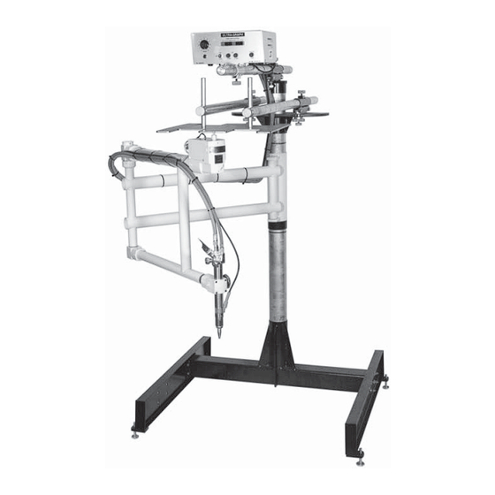
- Page 32 SECTION 4 Operation Ultra-Graph Floor Model Components Column Template Support Arm Pilot Pin Height Adjusting Collar Template Outer Arm Torch Holder Support Arm Leveling Screw Pivot Lock Knob Inner Arm Leveling Jacks Template Support Mount Bracket Tracing Rotor Base Assembly...
-
Page 33: Adjustments
Operation SECTION 4 Adjustments Arm Assembly Position Adjust the arm assembly vertically on the column to the desired working height by loosening the clamps in the hinge bracket (11) and raising the height adjusting collar (1). Secure height adjusting collar in place when the proper working height is obtained. -
Page 34: Adjusting Template Position
SECTION 4 Operation Adjusting Template Position Adjust the Ultra-Graph template support assembly on the column (9) in relation to the arm assembly, so that the midpoint of the knurled tracing rotor (3) on the tracing head strikes the vertical surface of the template evenly at all points of contact. -
Page 35: Operating Procedures
Operation SECTION 4 Operating Procedures RC Series Control Procedure Apply power to machine and select direction of machine movement around the template by placing the CW-CCW switch in the correct position Press the ADJUST pushbutton to start the drive motor. Select the desired cutting speed by adjusting the SPEED control knob. -
Page 36: Dc Series Control Procedure
CW-CCW switch back to its center OFF position and turning off gases. Positive Torch Ignition (PTI). ESAB patented tip-to-plate torch ignition is positive, dependable and trouble-free. There is no ignitor electrode to get in the way and to require constant adjustment. -
Page 37: Maintenance
Maintenance SECTION 5 Maintenance Introduction The ESAB Ultra-Graph Cutters are designed to operate over a long period of time with a minimum of maintenance. However, continued satisfactory operation of the machines depend upon the careful performance of a few simple inspection and cleaning procedures, as outlined in this section. -
Page 38: Daily Inspection And Maintenance
SECTION 5 Maintenance Daily Inspection and Maintenance Inspect the machine carefully each day before placing it in operation. Check the machine visually and perform the following steps which include an operating check of all machine components. If faults or malfunctions are noted in performing these procedures, refer to the Troubleshooting Chart. -
Page 39: Troubleshooting
Maintenance SECTION 5 Troubleshooting The Troubleshooting Chart serves as an aid in locating possible problems which may occur in operating the machine. Problem Possible Cause Remedy Motor will not operate No Power to the machine Check power supply and power input cable Fuse blown or faulty Check both line fuses and motor fuse located on the control front panel and replace. - Page 40 SECTION 5 Maintenance Problem Possible Cause Remedy Rotor slipping Hose dragging Free hoses Template too thin Use thicker template Templae or mchine not Level machine and /template level Worn or damaged drive Check and replace as required rotor Arm assembly motion Lubricate hinge pins with light machine oil restricted by sticking hinge pins...
-
Page 41: Understanding Operation
Maintenance SECTION 5 Understanding Operation The pantagraph type arm used on all Ultra-Graphs keeps the hinge points of the arm parallel to the tracing rotor and the torch. This provides a direct guidance system. Note that all four centerlines , and , are exactly parallel. -
Page 42: Solenoid Valve Repair
SECTION 5 Maintenance Solenoid Valve Repair The electrically operated solenoid valves, are used for remote control of gas supplies to the torches on RC Series Ultra-Graphs. They require no lubrication and very little maintenance. An exploded view of a two-way, normally closed, fully automatic, direct acting valve is hown at the left. - Page 43 Maintenance SECTION 5 Before working on any solenoid valve be CAUTION sure that all electrical power is off and that valve line pressure has been turned off . Be sure to bleed all gas lines before cleaning or replacing parts. Procedure To disassemble and reassemble valve, proceed as follows:...
-
Page 44: Electrical Schematics
SECTION 5 Maintenance Electrical Schematics The electrical systems of all Ultra-Graphs have been standardized and are designed with simple plug-in connections to all components. DC Control Schematic 1REC 3REC 2REC 115 VOLTS AC 60Hz For 50 Hz, See note, para. 4-8 See section 5 for Reference Designation Index Note: Wiring and Componenets shown... -
Page 45: Rc Control Schematic
Maintenance SECTION 5 RC Control Schematic IGNITE PIERCE NOTE Pressing OFF button releases all other buttons in switch assembly Cut O2 Fuel P.H O2 115 VOLTS AC 60Hz 2REC 1REC For 50Hz power, see note para. 4-8 4P 4J... - Page 46 SECTION 5 Maintenance This page intentionally blank. 5-10...
-
Page 47: Replacement Parts
Description List column. In addition, give the machine model number and serial number. Address all inquiries to your local ESAB Distributor or to ESAB Cutting Systems, P.O. Box 100545, Florence, South Carolina, 29501. -
Page 48: General Assembly
SECTION 6 Replacement Parts General Assembly... - Page 49 Replacement Parts SECTION 6 Item Part # Description 1691211 Insulator Template Support and Control Assy, RC Series, Standard 1001903 16901099 Arm Assy, Standard, 60” model Base Assy, Floor Model Ultra-Graph 12901001 Adapter, 90° Oxygen 12901003 Adapter, 90° Fuel gas 1310149 Hose, Oxygen, 7 ft (for 46 “...
-
Page 50: Control Mount Assembly
SECTION 6 Replacement Parts Control Mount Assembly... - Page 51 Replacement Parts SECTION 6 Item Part # Description Template Support and Control Assy, RC Series Standard (A) Template Support and Control Assy, DC Series Standard (C) 1251001 Control Assy, RC Series, Standard (for Assy A) (see Fig. 6 for detail parts) 1691001 Control Assy, DC Series, Standard (for Assy C) (see Fig.
-
Page 52: Standard Arm Assembly
SECTION 6 Replacement Parts Standard Arm Assembly... - Page 53 Arm Assy, Standard, 60” model 1691111 Knob 50944 Washer, Spring 13012155 Pinion, Torch lift, 32-pitch (standard) 13012183 Washer, Pinion 1291011 Nameplate, Emblem 12510113 Nameplate, ESAB 23112141 Plate, Gear coverDecal, 23112143 Gear coverplate 23112115 Cover, Motor 23101205 Dampener, Sound 2310139 Motor Assy, Standard (1B) 13501107...
-
Page 54: Base Assemblies
SECTION 6 Replacement Parts Base Assemblies Item Part # Description 1694201 Base Assy, Floor model Ultra-Graph (A) 2232726 Base Assy, Table model Ultra-Graph (B) 1301011 Column, 5 ft 1321011 Column, 4 ft 16901701 Leveler 16901049 Leg, Base 13201119 Support, Base column 1320169 Base, Table... -
Page 55: Rc Control
Replacement Parts SECTION 6 RC Control Item Part # Description 1251001 Control Assy, RC series for standard Ultra-Graph and Porta-Graph (A) 51719 Switch Assy, Pushbutton (1S) 50927 Fuseholder, (Line 2 Amp, Motor 1 Amp) 51913 Fuse, 3AG, 2 Amp, SioBio (1F, 2F) 51880 Fuse, 3AG, 1 Amp, SioBio (3F) 12501049... -
Page 56: Dc Series Control
SECTION 6 Replacement Parts DC Series Control Item Part # Description 1691001 Control Assy, DC Series for standard Ultra-Graph (A) 2310149 Control Assy, DC Series for Porta-Graph (C) 12801007 Switch, Toggle, DPST (Power Off ) (1S) 50927 Fuseholder, (Line 2 Amp, Motor 1 Amp) 51913 Fuse, 3AG, 2 Amp, SioBio (for Assy A, B) 1F, 2F) 2017049... - Page 57 Spacer Page...
- Page 58 Customer // Technical Support (843) 664-4405 (800) ESAB-123 (372-2123) ESAB Welding and Cutting Products PO BOX 100545 Ebenezer Road Florence, SC 29501-0545 http://www.esab.com ESAB Cutting Systems – Canada 6010 Tomken Road Mississauga, Ontario Canada L5T 1X9 Phone: (905) 670-0220 Fax: (905) 670-4879...
Need help?
Do you have a question about the Ultra-Graph RC60Floor and is the answer not in the manual?
Questions and answers