Table of Contents
Advertisement
Quick Links
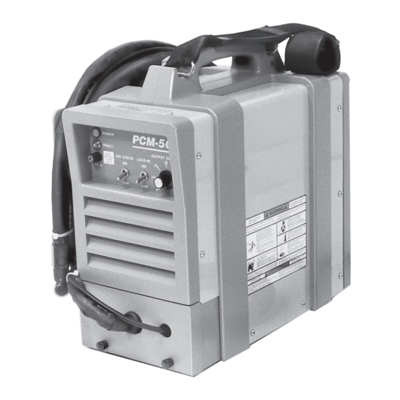
PLASMA ARC CUTTING PACKAGE
This manual provides installation and operation instructions for the following PCM-50i (Series A) cutting package:
P/N 34658 - 380/415, 50/60 Hz., 3-Phase
Starting with Serial No. PORI509000
These INSTRUCTIONS are for experienced operators. If you are not fully familiar with the principles of operation and
safe practices for electric welding equipment, we urge you to read our booklet, "Precautions and Safe Practices for
Arc Welding, Cutting, and Gouging," Form 52-529. Do NOT permit untrained persons to install, operate, or maintain
this equipment. Do NOT attempt to install or operate this equipment until you have read and fully understand these
instructions. If you do not fully understand these instructions, contact your supplier for further information. Be sure
to read the Safety Precautions before installing or operating this equipment.
Be sure this information reaches the operator.
You can get extra copies through your supplier.
INSTRUCTION MANUAL
PCM-50i
Series A
F-15-269
August, 1995
Advertisement
Table of Contents

Related Manuals for ESAB PCM-50i


Summary of Contents for ESAB PCM-50i
- Page 1 PCM-50i PLASMA ARC CUTTING PACKAGE Series A This manual provides installation and operation instructions for the following PCM-50i (Series A) cutting package: P/N 34658 - 380/415, 50/60 Hz., 3-Phase Starting with Serial No. PORI509000 These INSTRUCTIONS are for experienced operators. If you are not fully familiar with the principles of operation and safe practices for electric welding equipment, we urge you to read our booklet, "Precautions and Safe Practices for...
-
Page 2: Table Of Contents
Location ......................Inspection ......................Primary Electrical Input Connections ..............SECTION 3 OPERATION ..................... 11 Operation ......................11 PCM-50i Controls ....................11 Cutting with the PT-27 ..................11 Common Cutting Problems ................13 SECTION 4 MAINTENANCE ....................14 General ......................14 Inspection and Cleaning .................. -
Page 3: Safety Precautions
SAFETY PRECAUTIONS WARNING: hese Safety Precautions are for such as a garden hose, water pail, sand bucket, or your protection. They summarize precautionary portable fire extinguisher. Be sure you are trained in its information from the references listed in Addi- use. - Page 4 1. Always have qualified personnel perform the installation, D. Connect the work cable to the workpiece as close as troubleshooting, and maintenance work. Do not perform possible to the area being welded. any electrical work unless you are qualified to perform E.
-
Page 5: Description
(90-150 psi; ence material is also provided to assist in troubleshoot- 6-10 bar). The PCM-50i package uses the heavy-duty ing the cutting package. PT-27 torch to deliver cutting power for materials up to 1-1/4 inch (32 mm) thick. -
Page 6: Specifications
SECTION 1 DESCRIPTION 1.4 SPECIFICATIONS Refer to Tables 1-3, 1-4, and Figures 1-1 and 1-2 for PCM-50i technical specifications. Table 1-3. PCM-50i Specifications 40% Duty Cycle* 50 A @ 105 V dc Rated 60% Duty Cycle* 40 A @ 104 V dc... - Page 7 SECTION 1 DESCRIPTION Table 1-4. PT-27 Torch Specifications 7.3" (185 mm) Current Capacity (100% duty) 80 A DCSP Length of Service Lines 25 ft or 50 ft 3" (76 mm) Weight 25 ft (8m) 5.2 lbs (2.4 kg) 75° 1" (25.4 mm) 50 ft (15m) 9.6 lbs (4.4 kg) 1"...
-
Page 8: Installation
2.3 LOCATION CONNECTIONS (FIGURE 2-1) Adequate ventilation is necessary to provide proper cooling of the PCM-50i and the amount of dirt, dust, and excessive heat to which the equipment is exposed, should be minimized. There should be at least one foot... - Page 9 POWER SWITCH No. 12 CU/AWG 4-conduc- tor wire (380/415 V, 3-phase) PLUG & RECEPTACLE (purchase locally) COVER SAFETY INTERLOCK COVER WORK WORK CABLE SAFETY GROUND Allow at least 10 ft (3 m) between work and console Figure 2-1. PCM-50i Interconnection Diagram...
- Page 10 SECTION 2 INSTALLATION EARTH GROUND DO NOT ATTACH WORK CABLE TO PIECE BEING CUT WORK CABLE FREE GROUNDED WORK TABLE BE SURE WORK IS IN GOOD CONTACT WITH TABLE. EARTH GROUND WORK CABLE Figure 2-2. Ground and Work Cable Connections...
-
Page 11: Operation
460 volts. 3.3 CUTTING WITH THE PT-27 Use the following procedures to cut with the PT-27 torch Position the PCM-50i at least 10 feet (3 meters) from (Figure 3-4). the cutting area. Sparks and hot slag from the cut- ting operation can damage the unit. - Page 12 CONNECTION WORK CABLE TORCH GAS HOSE CONNECTION CONNECTION Figure 3-1. PCM-50i Controls For rapid re-starts, such as grate or heavy mesh NOTE cutting, do not release the torch switch. In the postflow mode, the arc can be re-started immedi- When replacing the nozzle, always inspect the elec- ately by depressing the torch switch.
-
Page 13: Common Cutting Problems
Damaged cutting nozzle. the probable cause of each. If problems are determined Loose cutting nozzle. to be caused by the PCM-50i, refer to the maintenance Heavy spatter. section of this manual. If the problem is not corrected after referring to the maintenance section, contact your Uneven Arc. -
Page 14: Maintenance
Use only recommended 4.3 PT-27 TORCH CONSUMABLE PARTS replacement parts. Make sure power switch on PCM-50i is in OFF posi- Be sure that the wall disconnect switch or wall tion before working on the torch. -
Page 15: Flow Switch
SECTION 4 MAINTENANCE The valve pin is a crucial member of the system. Its function is to open the gas flow check valve that is permanently assembled within the torch head. If the pin is not correctly placed in the electrode, the valve will not open and the system will not function. VALVE PIN DO NOT REVERSE. -
Page 16: Troubleshooting
SECTION 5 TROUBLESHOOTING The cause of control malfunctions can be found by 5.1 TROUBLESHOOTING referring to the sequence of operations and electrical schematic diagram (Figure 5-1) and checking the vari- ous components. A volt-ohmmeter will be necessary for some of these checks. ELECTRIC SHOCK CAN KILL! Be sure that all pri- mary power to the machine has been externally disconnected. - Page 17 SECTION 5 TROUBLESHOOTING No Air Is air hose connected? Connect Is air adjusted to 65 psig (4.4 bar)? Adjust Does air come on with air check switch? • No electrode in torch • No valve pin in torch • Replace electrode Check continuity of torch switch •...
- Page 18 Is air check switch OFF? Turn switch OFF Does arc start when nozzle contacts work without depressing torch switch? Check for short in torch switch Does air flow even when PCM-50i power switch is OFF? Replace Repair power solenoid valve...
- Page 19 Is main 380/415 volt switch ON? Turn on main disconnect Is plug in receptacle? Insert plug in receptacle Is cooling fan turning? Replace pilot light Check voltage at receptacle and input power line Check main fuses Faulty power switch on PCM-50i...
- Page 20 Fault light will energize if voltage falls below 340 volts for 0.3 seconds or exceeds 400 volts even for an instant. The light will not turn OFF even when correct voltage is restored. Reset by placing PCM-50i power switch OFF and then ON again.
-
Page 21: Sequence Of Operation
SECTION 5 TROUBLESHOOTING 5.3 Sequence of Operation LOCK-IN "OFF" position PUSH RELEASE TORCH SWITCH OPEN CLOSE GAS SOLENOID VALVE 2 SEC. PREFLOW 10 SEC Postflow OPEN FLOW SWITCH CLOSE FAULT OVERLOAD LIGHT ENERGIZE HF CIRCUIT INVERTER CUTTING ARC (CURRENT) NOTES: When the torch switch is pushed during postflow period, the postflow and preflow times are canceled, and the HF is energized immediately. - Page 22 SECTION 5 TROUBLESHOOTING LOCK-IN "ON" position PUSH RELEASE PUSH RELEASE TORCH SWITCH OPEN CLOSE GAS SOLENOID VALVE PREFLOW 2 SEC. 10 SEC Postflow POSTFLOW CLOSE OPEN FLOW SWITCH FAULT PILOT LIGHT ENERGIZE HF CIRCUIT INVERTER CUTTING ARC (CURRENT) NOTES: When the torch switch is pushed during postflow period, the postflow and preflow times are canceled, and the HF is energized immediately.
- Page 23 Figure 5-1. PCM-50i (Series A) Schematic Diagram (380/415 V, 3-Phase Input)
- Page 24 Figure 5-2. PCM-50i (Series A) Wiring Diagram (380/415 V, 3-Phase Input)
-
Page 25: Replacement Parts
SECTION 6 REPLACEMENT PARTS To assure proper operation, it is recommended that only 6.1 ORDERING genuine listed parts and products be used with this equipment. The use of any other parts may void your Always provide the series or serial number of the unit on warranty. - Page 26 SECTION 6 REPLACEMENT PARTS 13,14 Figure 6-1. PCM-50i (Series A) Power Source (Front View) ITEM PART CIRCUIT REQ. DESCRIPTION SYMBOL 33953GY HOUSING, HANDLE & STRAP (LEFT) 34556GY HOUSING, HANDLE & STRAP (RIGHT) 951496 STRAP (HOOK 2-REQ’D: 951536) 32132 CABINET, SILKSCREENED...
- Page 27 SECTION 6 REPLACEMENT PARTS REF 12 2,19 FIGURE 6-1 REF 5 FIGURE 6-6 21,20 VIEW A-A Figure 6-3. PCM-50i (Series A) Power Source (Left Side View) ITEM PART CIRCUIT REQ. DESCRIPTION SYMBOL 32949LG COVER 13735308 RELAY, 120 V AC, 20 A...
- Page 28 SECTION 6 REPLACEMENT PARTS REF 4 FIGURE 6-6 Figure 6-5. PCM-50i (Series A) Power Source (Right Side View) ITEM PART CIRCUIT REQ. DESCRIPTION SYMBOL 951185 MODULE, DIODE, 100 A, 600 V, 100 NS (PAD-951518) D1,D2 32969 REACTOR ASSY., HIGH FREQUENCY 17721020 RESISTOR, 20, 25 W, N.I.
- Page 29 SECTION 6 REPLACEMENT PARTS Figure 6-6. PCM-50i (Series A) Power Source (Rear View) ITEM PART CIRCUIT REQ. DESCRIPTION SYMBOL 33955GY HOUSING, REGULATOR 33950GY HOUSING, REAR 33952GY HOUSING, WIRE WRAP/UTILITY BOX 58V75 ADAPTOR, BULKHEAD 951181 ON/OFF SWITCH, CIRC. BRKR., 50 A...
- Page 32 F-15-269 8/95 1.5M Printed in U.S.A.
Need help?
Do you have a question about the PCM-50i and is the answer not in the manual?
Questions and answers