
Related Manuals for Chemitec 50 Series


Summary of Contents for Chemitec 50 Series
- Page 1 50 SERIES 8 PARAMETERS MULTIPARAMETER PLUG & PLAY ANALYZER TECHNICAL MANUAL P/N: …………………. Rev. 1 Ver. 1 EDITION Agoust 2018 draft...
- Page 2 GENERAL CLAUSES Despite the fact that the utmost attention has been given taken in the preparation of this document, CHEMITEC s.r.l. cannot guarantee the accuracy of all information contained and cannot be held responsible for any consequent mistakes or damages that may arise from its use or application.
-
Page 3: Table Of Contents
CONNECTIONS TO THE POWER SUPPLY ..................15 3.1.2.1 Electrical Connections to the dosage systems (Users) ................ 16 3.1.2.1.1 Connection terminal box for 50 Series ..................17 3.1.2.1.2 Connection terminal box for J-Box ....................19 3.1.2.2 Connections to the Power Supply ......................20 3.1.3... - Page 4 SPECIAL CAUTIONS FOR CRITICAL COMPONENTS ................37 APPENDIX: TABLES OF SOLUBILITY AND CONVERSION-CORRECTION FACTORS ....38 MODBUS PROTOCOL ............................39 WARRANTY ................................. 49 REQUEST FOR ASSISTANCE ........................... 50 PROCEDURE OF REQUEST FOR TECHNICAL ASSISTANCE ..............50 MAIN CHEMITEC OFFICES ......................... 50...
-
Page 5: General
If for any reason it is ruined, incomplete or inadequate please contact CHEMITEC in order to reintegrate or replace the non-compliant manual immediately. -
Page 6: Declaration Of Responsibility By The Manufacturer
/ instrument DECLARATION OF RESPONSIBILITY BY THE MANUFACTURER CHEMITEC will be held responsible for the safety, reliability and performance of the equipment only if used in compliance with the following conditions: •... -
Page 7: Safety Of The Operative Environment
SAFETY OF THE OPERATIVE ENVIRONMENT • The panel of the 50 Series device is protected against the introduction of liquids. Avoid subject the equipment to the risk of dripping water, sprays of water or immersion in water and the use in environments in which such risks may be present. Equipment in which liquids may have accidentally penetrated must be immediately switched off, cleaned and controlled by authorised and qualified personnel. -
Page 8: Graphic Symbols
50 Series 8P MULTIPARAMETER PLUG & PLAY ANALYZER TECHNICAL MANUAL P/N XXX-0000 Rev.4 Ver.1.1 Therefore, we recommend that service personnel and/or maintenance personnel operate with the utmost care, pointing out any changes to the safety parameters immediately, in order to avoid the creation of any potentially dangerous situations. -
Page 9: Caution Symbol
IP66 INFORMATION ON RECYCLING AND USE OF MATERIALS CHEMITEC, in accordance with specific European regulations, aims at constant improvement of development and of production procedures of its equipment with the objective of drastically reducing the negative impact on the environment caused by parts, components, consumption materials, packaging and the equipment itself at the end of its life cycle. -
Page 10: Special Attention To Critical Components
50 Series 8P MULTIPARAMETER PLUG & PLAY ANALYZER TECHNICAL MANUAL P/N XXX-0000 Rev.4 Ver.1.1 The equipment is made in such a way as to guarantee the easy separation or dismantling of the materials containing contaminants compared with others, in particular during maintenance operations and the replacement of parts. -
Page 11: General Description
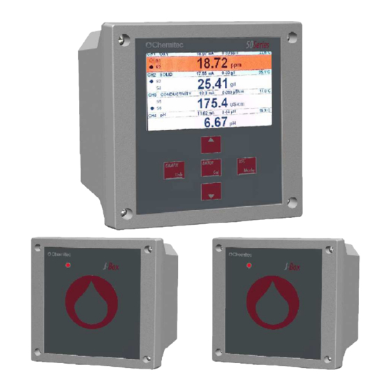
Treatment and Discharge of Industrial Water • Fish farm • Primary Water, Drinking Water Figure 1 – Wall mounting Multiparameter analyzer (50 Series) P ARAMETERS DETECTED BY THE INSTRUMENT • MEASURING OF PH • MEASURING OF ORP • MEASURING OF INFRARED AND NEFELOMETRIC TURBIDITY •... -
Page 12: Main Charactheristics
50 Series 8P MULTIPARAMETER PLUG & PLAY ANALYZER TECHNICAL MANUAL P/N XXX-0000 Rev.4 Ver.1.1 MAIN CHARACTHERISTICS • Up to four simultaneous digital measurements and a fifth analogue measure 4-20mA. • Measuring of Temperature using the PT100/PT1000 probe • Programming key pad with 5 keys •... -
Page 13: Technical Characteristics For Turbidity And Suspended Solids
50 Series 8P MULTIPARAMETER PLUG & PLAY ANALYZER TECHNICAL MANUAL P/N XXX-0000 Rev.4 Ver.1.1 2.2.4 TECHNICAL CHARACTERISTICS FOR TURBIDITY AND SUSPENDED SOLIDS Due to the connected probe: Digital Probe Measuring Range / Measuring Unit S461LT 0.00÷10.00 / 000.00÷100.00 NTU 0 ÷ 4 NTU S461T 0 ÷... -
Page 14: Technical Characteristics For Secondary Temperature Measuring
50 Series 8P MULTIPARAMETER PLUG & PLAY ANALYZER TECHNICAL MANUAL P/N XXX-0000 Rev.4 Ver.1.1 2.2.12 TECHNICAL CHARACTERISTICS FOR SECONDARY TEMPERATURE MEASURING Sensor PT100/PT1000 Measurement range 0 ÷ +130°C 2.2.13 TECHNICAL CHARACTERISTICS FOR 4-20MA AUX INPUT MEASURING Measurement range 4-20Ma Freely programmable measure 2.2.14... -
Page 15: Controls, Indicators And Connections
50 Series 8P MULTIPARAMETER PLUG & PLAY ANALYZER TECHNICAL MANUAL P/N XXX-0000 Rev.4 Ver.1.1 CONTROLS, INDICATORS AND CONNECTIONS Figure 2 – Wall instrument, front panel 1. Visualizer with LCD Display 2. UP key 3. ESC key 4. ENTER key 5. DOWN key 6. -
Page 16: Graphic Display
50 Series 8P MULTIPARAMETER PLUG & PLAY ANALYZER TECHNICAL MANUAL P/N XXX-0000 Rev.4 Ver.1.1 GRAPHIC DISPLAY The graphic display allows for visualization of the various programming menus and, in the measuring method (RUN), visualization of the measurements and of the state of operation. -
Page 17: Division Of The Graphical Display Into Areas In The Run Method
50 Series 8P MULTIPARAMETER PLUG & PLAY ANALYZER TECHNICAL MANUAL P/N XXX-0000 Rev.4 Ver.1.1 2.4.2 DIVISION OF THE GRAPHICAL DISPLAY INTO AREAS IN THE RUN METHOD Each of the channels shows the value of the measurement, the state of the assigned relays, the value of the current output and the possible temperature value. -
Page 18: Installation
TECHNICAL MANUAL P/N XXX-0000 Rev.4 Ver.1.1 INSTALLATION Although the unit is suitable for installation in outdoor environments, it is recommended to avoid direct exposure to sun and weather. Before installing the 50 Series carefully read the instructions provided below. COMPOSITION OF THE SUPPLY The supply consists of just one package which contains the following parts: •... -
Page 19: Connections To The Power Supply
50 Series 8P MULTIPARAMETER PLUG & PLAY ANALYZER TECHNICAL MANUAL P/N XXX-0000 Rev.4 Ver.1.1 3.1.2 INSTALLATION OF 144X144 ELECTRICAL PANEL DEVICE The wall must be perfectly smooth in order to allow for perfect adhesion of the electrical panel close to the device. -
Page 20: Electrical Connections To The Dosage Systems (Users)
50 Series 8P MULTIPARAMETER PLUG & PLAY ANALYZER TECHNICAL MANUAL P/N XXX-0000 Rev.4 Ver.1.1 CAUTION The electric line must be fitted with a suitable life-saving device and magneto-thermal, in compliance with correct installation norms. The supply disconnecting device must be easily accessible after installing the instrument and must be marked as the disconnection of the unit. -
Page 21: 3.1.3.1.1 Connection Terminal Box For 50 Series
Figure 7 Examples of connection with users NOTE The layouts indicated above are typically indicative as details of all of the protection and safety devices necessary are missing. 3.1.3.1.1 Connection terminal box for 50 Series Figure 8 Connections terminal box for 50Series CLAMP GRAPHIC... - Page 22 50 Series 8P MULTIPARAMETER PLUG & PLAY ANALYZER TECHNICAL MANUAL P/N XXX-0000 Rev.4 Ver.1.1 CLAMP GRAPHIC DESCRIPTION RS485 (B-) Relay for Wash and Temp (N.C. contact) Relay for Wash and Temp (N.O. contact) Relay for Alarm (N.C. contact) Relay for Alarm (N.O. contact) Relay for Set Point 4 (N.C.
-
Page 23: 3.1.3.1.2 Connection Terminal Box For J-Box
50 Series 8P MULTIPARAMETER PLUG & PLAY ANALYZER TECHNICAL MANUAL P/N XXX-0000 Rev.4 Ver.1.1 In case of 3 wires level probe connection:: CLAMP GRAPHIC DESCRIPTION Blue Wire Level Sensor Digital input (-) Brown Wire Level Sensor Digital input (+) Black Wire Level Sensor 3.1.3.1.2 Connection terminal box for J-Box... -
Page 24: 3.1.3.2 Connections To The Power Supply
The J-Box is powered by the 50Series instrument connected. 3.1.4 DIGITAL PROBES CONNECTION The 50 Series in its stand-alone configuration can be connected with up to 2 digital probes having different addresses (see figure 9). Power Supply Figure 10 Connections with 2 digital probes... - Page 25 50 Series 8P MULTIPARAMETER PLUG & PLAY ANALYZER TECHNICAL MANUAL P/N XXX-0000 Rev.4 Ver.1.1 The instrument must be connected with the J-Box in order to connect the entire system with up to 4 digital probes having different addresses (see figure 10, next page).
- Page 26 50 Series 8P MULTIPARAMETER PLUG & PLAY ANALYZER TECHNICAL MANUAL P/N XXX-0000 Rev.4 Ver.1.1 Power Supply Figure 12.1 Connections with J-Box and 8 probes The display page allows you to display 4 measurements at the same time, if you want to see the other 4 measurements simply change pages...
-
Page 27: Methods Of Use
50 Series 8P MULTIPARAMETER PLUG & PLAY ANALYZER TECHNICAL MANUAL P/N XXX-0000 Rev.4 Ver.1.1 METHODS OF USE START UP OF THE SYSTEM Once the electronic device and the measuring probe(s) have been connected, programming of the software must be carried out in order to determine “personalisation” of parameters for correct use of the equipment. - Page 28 50 Series 8P MULTIPARAMETER PLUG & PLAY ANALYZER TECHNICAL MANUAL P/N XXX-0000 Rev.4 Ver.1.1 SERIAL NO. (Allows to visualize the serial number of the device on the display) PROBE AVAILABLE (Allows to manually choose the type of connected probes) DIGITAL INPUT (Permette di abbinare l'evento di chiusura ingresso digitale all'apertura dei relè...
-
Page 29: Outputs Menu
50 Series 8P MULTIPARAMETER PLUG & PLAY ANALYZER TECHNICAL MANUAL P/N XXX-0000 Rev.4 Ver.1.1 PROBE AVAILABLE (This menu allows you to check which probes have been recognized by the system and manually add a probe without using the “self-recognition” of the... - Page 30 50 Series 8P MULTIPARAMETER PLUG & PLAY ANALYZER TECHNICAL MANUAL P/N XXX-0000 Rev.4 Ver.1.1 Measure Figure 13 – Threshold operation Furthermore by acting on the Time ON and Time OFF parameters it is possible to define a DELAY time or a TIMED operation of the Relay during its activation.
- Page 31 50 Series 8P MULTIPARAMETER PLUG & PLAY ANALYZER TECHNICAL MANUAL P/N XXX-0000 Rev.4 Ver.1.1 PID-PWM By defining the Set Point as PID-PWM, through Relay 1, it is possible to activate a pump with an ON/OFF command almost as if it had a proportional adjustment. For this function the time period must be programmed (in seconds) within which the calculation of the PWM adjustment will come about.
- Page 32 50 Series 8P MULTIPARAMETER PLUG & PLAY ANALYZER TECHNICAL MANUAL P/N XXX-0000 Rev.4 Ver.1.1 The user, in case of alarm, can decide if mA output goes to 4 mA or remains frozen at the last value. The PID function allows for three adjustments to handle the dose.
-
Page 33: Calibrations Menu
50 Series 8P MULTIPARAMETER PLUG & PLAY ANALYZER TECHNICAL MANUAL P/N XXX-0000 Rev.4 Ver.1.1 3.3.3 CALIBRATIONS MENU 3.0 CALIBRATIONS (It allows you to perform all calibrations of each probe. Entering the menu you choose which probe calibration, depending on the type of probe connected you can do several calibrations). - Page 34 50 Series 8P MULTIPARAMETER PLUG & PLAY ANALYZER TECHNICAL MANUAL P/N XXX-0000 Rev.4 Ver.1.1 If ”Faulty Probe” is displayed, we recommend: To check the electrode physical integrity and the protection cap removing To assure the cleaning of the porous plug, if not, dip the electrode into a regenerant...
- Page 35 50 Series 8P MULTIPARAMETER PLUG & PLAY ANALYZER TECHNICAL MANUAL P/N XXX-0000 Rev.4 Ver.1.1 If you use the probe holder pss8 it is better not to execute the calibration of the first point. Circulate water with known solution, making sure that there are no air bubbles in the circuit: to eliminate them you can create a small pressure partially closing the output stream.
- Page 36 50 Series 8P MULTIPARAMETER PLUG & PLAY ANALYZER TECHNICAL MANUAL P/N XXX-0000 Rev.4 Ver.1.1 + OR NO CALIBRATION AUTOMATIC With the automatic calibration mode, once inserted the probe in a known sample, the user can freely enter the value of the known solution, in this way the reading of the probe on a point is aligned.
-
Page 37: Archive Menu
50 Series 8P MULTIPARAMETER PLUG & PLAY ANALYZER TECHNICAL MANUAL P/N XXX-0000 Rev.4 Ver.1.1 CONDUCTIVITY CALIBRATION CALIBRATION The conductivity calibration foresees two calibration points. The first calibration must be done at 0µS !! After inputting the temperature compensation value press ENTER key and dip the probe into a solution at 0µS or expose it to air after proper drying. -
Page 38: Graphic Measuring Menu
50 Series 8P MULTIPARAMETER PLUG & PLAY ANALYZER TECHNICAL MANUAL P/N XXX-0000 Rev.4 Ver.1.1 archive can be transferred to PC via C_NET software, or saved to an external USB flash drive connected to the USB port of the instrument.) In this part of the programme it is possible to visualise data in the form of a table as long as the archives are not empty. -
Page 39: Manual Control Menu
50 Series 8P MULTIPARAMETER PLUG & PLAY ANALYZER TECHNICAL MANUAL P/N XXX-0000 Rev.4 Ver.1.1 3.3.6 MANUAL CONTROL MENU 6.0 MANUAL CONTROL (This step of the programme is useful for all functional controls eg. Upon installation to check functioning of the entire system, as it allows you to view and manually activate the inputs and outputs of the device. - Page 40 50 Series 8P MULTIPARAMETER PLUG & PLAY ANALYZER TECHNICAL MANUAL P/N XXX-0000 Rev.4 Ver.1.1 • Status of the Washing Relay • System errors • Storage of Data in the Archive • Archive Full Holding the ESC key for 3-4 seconds during the run functions By pressing this key you will enter the probe self-recognizing mode of the instrument.
-
Page 41: User Maintenance
50 Series 8P MULTIPARAMETER PLUG & PLAY ANALYZER TECHNICAL MANUAL P/N XXX-0000 Rev.4 Ver.1.1 USER MAINTENANCE SPECIAL CAUTIONS FOR CRITICAL COMPONENTS An LCD (Liquid Crystal Display) is incorporated into the equipment and it contains small amounts of toxic materials. In order to avoid damages to people and to limit the negative effects on the environment,... -
Page 42: Appendix: Tables Of Solubility And Conversion-Correction Factors
50 Series 8P MULTIPARAMETER PLUG & PLAY ANALYZER TECHNICAL MANUAL P/N XXX-0000 Rev.4 Ver.1.1 APPENDIX: TABLES OF SOLUBILITY AND CONVERSION-CORRECTION FACTORS TABLE 1 Solubility of oxygen in water at 760 mm Hg and 100% of relative humidity °C ppm O °C... -
Page 43: Modbus Protocol
50 Series 8P MULTIPARAMETER PLUG & PLAY ANALYZER TECHNICAL MANUAL P/N XXX-0000 Rev.4 Ver.1.1 MODBUS PROTOCOL Characteristics • Standard MODBUS Protocol RTU type • Physical Layer: two wires RS485 (half-duplex) • Alternative Physical Layer: USB • 8 bit, Equality N, 1 Stop bit •... - Page 44 50 Series 8P MULTIPARAMETER PLUG & PLAY ANALYZER TECHNICAL MANUAL P/N XXX-0000 Rev.4 Ver.1.1 00 Instrument name ('504P') 4 bytes ASCII 02 Instrument Serial Number (0...65535) 04 ModBus ID (1...254) 06 Probe Type 1 (meas_sel[0]) (see probe Type Codes) 08 Probe Type 2 (meas_sel[1])
- Page 45 50 Series 8P MULTIPARAMETER PLUG & PLAY ANALYZER TECHNICAL MANUAL P/N XXX-0000 Rev.4 Ver.1.1 242 Measure Unit 1 (characters 5,6,7,8) (read only) 244 Measure Unit 2 (characters 1,2,3,4) (read only) 246 Measure Unit 2 (characters 5,6,7,8) (read only) 248 Measure Unit 3 (characters 1,2,3,4) (read only)
- Page 46 50 Series 8P MULTIPARAMETER PLUG & PLAY ANALYZER TECHNICAL MANUAL P/N XXX-0000 Rev.4 Ver.1.1 2 consecutive registers of the 4 bytes that make up the floating point variable. Because each value has two Modbus registers (4 bytes) and that the values begin to even address registers, was introduced a control that the Starting Address of registers required is even and that the number of registers required is even itself.
- Page 47 50 Series 8P MULTIPARAMETER PLUG & PLAY ANALYZER TECHNICAL MANUAL P/N XXX-0000 Rev.4 Ver.1.1 218 AUX Measure name 1 (characters 5,6,7,8) 220 AUX Measure unit (characters 1,2,3,4) 222 AUX Measure unit (characters 5,6,7,8)
- Page 48 50 Series 8P MULTIPARAMETER PLUG & PLAY ANALYZER TECHNICAL MANUAL P/N XXX-0000 Rev.4 Ver.1.1 Archive download at record blocks Sequency: 1. Single record size request. 2. Existing record number request. 3. Current record request 4. Record acquiring cycle a. If previous request goes well Request next record b.
- Page 49 50 Series 8P MULTIPARAMETER PLUG & PLAY ANALYZER TECHNICAL MANUAL P/N XXX-0000 Rev.4 Ver.1.1 Answer Byte Description Device Slave Number BHIST_ARC_FN = 0x44 (Function) BHIST_ARC_NUM_REC = 0x03 (Subfunction) Numero Records (lo) Numero Records (hi) CRC (lo) CRC (hi) Current record request...
- Page 50 50 Series 8P MULTIPARAMETER PLUG & PLAY ANALYZER TECHNICAL MANUAL P/N XXX-0000 Rev.4 Ver.1.1 If Data size=0 : a record over than the the existings has prompted Reset archive request Request Byte Description Device Slave Number HIST_ARC_RESET = 0x45 (Function)
- Page 51 50 Series 8P MULTIPARAMETER PLUG & PLAY ANALYZER TECHNICAL MANUAL P/N XXX-0000 Rev.4 Ver.1.1 bit4 = (Alarm) bit5 = (Wash)
- Page 52 50 Series 8P MULTIPARAMETER PLUG & PLAY ANALYZER TECHNICAL MANUAL P/N XXX-0000 Rev.4 Ver.1.1 PROBE TYPE CODE FTU_1 //Photometric Turbidimeter Probe FTU_2 //Photometric Turbidimeter Probe FTU_3 //Photometric Turbidimeter Probe FTU_4 //Photometric Turbidimeter Probe OX_1 //Chemitec Oxygen probe OX_2 //Chemitec Oxygen probe...
-
Page 53: Warranty
MULTIPARAMETER PLUG & PLAY ANALYZER TECHNICAL MANUAL P/N XXX-0000 Rev.4 Ver.1.1 WARRANTY Chemitec s.r.l. will replace or repair at its own sole option, those parts that may eventually manifest defects in manufacturing or operating, despite of a diligent and proper use by the customer. -
Page 54: Request For Assistance
In the case of a fault to the equipment or in the case of partial or incorrect functioning that cannot be resolved through the ordinary maintenance operations described in this manual or in the documentation attached, we kindly ask you to contact a CHEMITEC office or branch or your nearest dealer or authorised assistance centre.
Need help?
Do you have a question about the 50 Series and is the answer not in the manual?
Questions and answers