
Related Manuals for Chemitec 4204


Summary of Contents for Chemitec 4204
- Page 1 4204 FLOW METER With ULTRASOUND measurement sensor TECHNICAL MANUAL P/N: …………………. Rev. 5 Ver. 3.4 RELEASE December 2016...
- Page 2 Although we have paid maximum attention and care in processing this document, CHEMITEC s.r.l. cannot guarantee the exactness of all information herein contained and thus cannot be held liable for errors that this may entail nor for the damages that may result from the use or application thereof.
-
Page 3: Table Of Contents
4204 FLOW METER TECHNICAL MANUAL P/N XXX-0000 Rev. 5 Ver. 3.4 TABLE OF CONTENTS GENERAL ................................1 MANUAL INFORMATION ..........................1 1.1.1 CONVENTIONS ............................1 MANUFACTURER DECLARATION OF LIABILITY ................... 2 LIMITS OF USE AND SAFETY PRECAUTIONS ..................2 1.3.1 ELECTRIC SAFETY .......................... - Page 4 EXIT MENU [5.0] ............................38 MAINTENANCE ..............................39 SPECIAL ATTENTION FOR CRITICAL COMPONENTS ................39 MODBUS PROTOCOL ............................40 10 WARRANTY ................................. 44 11 REQUEST FOR SERVICE ..........................45 11.1 PROCEDURE FOR SERVICE REQUEST ..................... 45 11.2 MAIN CHEMITEC OFFICES ......................... 45...
-
Page 5: General
English versions. For Countries with languages different than those versions above mentioned, the official manual in the one in Italian language. CHEMITEC shall not be held responsible for any translations in different languages carried out by distributors or users. -
Page 6: Manufacturer Declaration Of Liability
TECHNICAL MANUAL P/N XXX-0000 Rev. 5 Ver. 3.4 MANUFACTURER DECLARATION OF LIABILITY CHEMITEC shall be liable for the safety, reliability and performance of the instrument only if utilised in compliance with the following conditions: Calibrations, modifications and repairs must be performed by personnel expressly qualified and •... -
Page 7: Safety Of Operating Environment
1.3.2 SAFETY OF OPERATING ENVIRONMENT • The 4204 unit is watertight against any infiltration of liquids. Avoid subjecting the equipment to risks of seepage, sprays or anything else and do not use in areas in which such risks are possible. Any power units in which liquids may have accidentally fallen should be immediately turned off, cleaned and checked by authorised and qualified personnel. -
Page 8: Graphic Signs
4204 FLOW METER TECHNICAL MANUAL P/N XXX-0000 Rev. 5 Ver. 3.4 GRAPHIC SIGNS The following Table 1-1 indicates the drawings, relative descriptions and position of all the graphic signs placed on the instrument panel and on any other external instruments or devices to which it can be connected. -
Page 9: Plate Data
Figure 1-1 Configuration of the Unit Number Plate INFORMATION ON RECYCLING AND REUTILISATION OF MATERIALS CHEMITEC objectives, in compliance with the specific European directives, including the directive 2002/95/CE, traditionally identified by RoHS, aims at continuously improving planning and manufacturing of its own instruments, in order to reduce to the minimum the negative impact on environment about handling the component parts, consumable materials, packing and instrument itself, at the end of its useful life. -
Page 10: General Description
• total volume temperature • status of the analogical outputs • • counters Figure 2-1 – Ultrasounds level meter and regulator (4204) MAIN FEATURES Ultrasound flow measurement • • Automatic temperature compensation • Bubble 6 keys programming keyboard Graphic Display •... -
Page 11: Unit Hardware Main Features
4204 FLOW METER TECHNICAL MANUAL P/N XXX-0000 Rev. 5 Ver. 3.4 UNIT HARDWARE MAIN FEATURES • Internal Data logger (flash 4 Mbit) with possibility of graphic and table display of measurements trends. • Five independent set points for threshold control, with programming of the work field (hysteresis). - Page 12 4204 FLOW METER TECHNICAL MANUAL P/N XXX-0000 Rev. 5 Ver. 3.4 Table 2-2 Operating Specifications Measurement Recording Instant flow Volume counted Recordings Intervals 1/275/10/15/20/30/60 min 5/10/30 min. 1/2/6/12/24 h. Type Circular /Filling Circular / Filling Graphic display of the minimum, maximum...
-
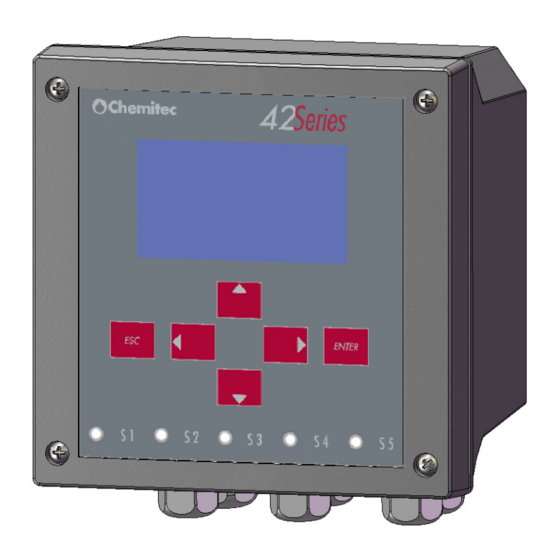
Page 13: Controls And Indicators
4204 FLOW METER TECHNICAL MANUAL P/N XXX-0000 Rev. 5 Ver. 3.4 CONTROLS AND INDICATORS Controls and indicators are grouped on the front of the Unit so that they can be easily available for the operator. Figure 2-2 identifies all the Unit controls and connecting devices. -
Page 14: Installation
TECHNICAL MANUAL P/N XXX-0000 Rev. 5 Ver. 3.4 INSTALLATION Although the unit is suitable for installation in outdoor environments, it is recommended to avoid direct exposure to sun and weather. Before installing the 4204 carefully read the instructions provided below. COMPOSITION OF THE SUPPLY The supply consists of just one package which contains the following parts: 1 electrical control and command panel PN ....????? -
Page 15: Installation Of 144X144 Electrical Panel Device
The thickness of the panel must not exceed 5 mm. The perforation DIMA must comply with the following layout: Figure 3 – Encumbrance and Dima for perforation of the panel Mechanical Dimensions 4204 144x144 Panel Mounted 144x144x86,5mm Dimensions (L x H x P) 70mm... -
Page 16: Terminal Board Connections
4204 FLOW METER TECHNICAL MANUAL P/N XXX-0000 Rev. 5 Ver. 3.4 3.1.3 TERMINAL BOARD CONNECTIONS The terminal board connections and the definitions of the Unit connections to the plant to be placed under control are shown in Figure 3-2 and 3-3 (depending by the connected probe). -
Page 17: Electrical Connections To The Systems
4204 FLOW METER TECHNICAL MANUAL P/N XXX-0000 Rev. 5 Ver. 3.4 In any case, it is always advisable to verify the quality of Grounding. Often Ground connections, found mostly within industrial environments, are themselves generators of interferences; where in doubt about the quality, it is preferable to connect it to a pole dedicated only to the unit plant. -
Page 18: Operating Mode - General
4204 FLOW METER TECHNICAL MANUAL P/N XXX-0000 Rev. 5 Ver. 3.4 OPERATING MODE – GENERAL This chapter describes the procedures that must be followed to enable all the functions of the programme. The description is distributed between text and Figures: •... -
Page 19: Enabling The System
4204 FLOW METER TECHNICAL MANUAL P/N XXX-0000 Rev. 5 Ver. 3.4 ENABLING THE SYSTEM After installing the electronic central control unit, it is necessary to go on programming the software, which will allows for “personalising” the settings for a correct use of the instrument. -
Page 20: Run Mode
4204 FLOW METER TECHNICAL MANUAL P/N XXX-0000 Rev. 5 Ver. 3.4 RUN MODE This mode keeps operation of the plant under control in real time. The operative parameters are represented on the screen by the power unit, according to the symbols shown in Figure 6-1 and in Table 6-1. - Page 21 4204 FLOW METER TECHNICAL MANUAL P/N XXX-0000 Rev. 5 Ver. 3.4 Table 6-1 Operating symbols DISPLAY DESCRIPTION 12-04-05 Syatem Date Wait- Freeze measurements and outputs phase Contrast Password Enabled If communication is lost, "PROBE ERROR" will appear in the middle of the screen If the eco is lost for a period exceeding the period indicated, icon 4 will be activated.
- Page 22 4204 FLOW METER TECHNICAL MANUAL P/N XXX-0000 Rev. 5 Ver. 3.4 220V 12/09/05 16:41 12/09/05 16:41 ENTER 0 l/s 0 l/s 0003496.54m R0000106.59m Programming Mode Are you sure ? DOWN 12/09/05 16:41 0 l/s 0003496.54m ENTER 0.0cm DOWN 12/09/05 16:41 0 l/s 0003496.54m...
-
Page 23: Programming Mode
In order to enter the programming mode press “ESC”; a message will appear requesting further confirmation: if "ESC" is pressed again, it will return to the "RUN" mode; if "ENTER" is pressed all of the 4204 functions will be immediately disabled and it will move onto the "PROGRAMMING" mode. -
Page 24: Activation Of Functions
4204 FLOW METER TECHNICAL MANUAL P/N XXX-0000 Rev. 5 Ver. 3.4 VIEW ON THE GRAPHIC DESCRIPTION DISPLAY “ANALOGUE OUTPUT mA” Analogue outputs settings in current “ARCHIVE” Setting mode for filing and displaying data “EXIT MENU” Return to the measuring operating mode (“RUN”) - Page 25 4204 FLOW METER TECHNICAL MANUAL P/N XXX-0000 Rev. 5 Ver. 3.4 square brackets. In the case of this example, the menu corresponding to the following icon has been selected “SETUP” [1] b) Press “ENTER” to activate the menu. The programme proposes the first of the operative programmes on the screen.
- Page 26 4204 FLOW METER TECHNICAL MANUAL P/N XXX-0000 Rev. 5 Ver. 3.4 “FUNC” This representation mode indicates other screens apart from the one represented, that contain further parameters. In order to visualise the alternatives available, proceed as follows: − Position the black string on the item "FUNC" using the "UP” and “DOWN” keys, if it is present it is always the first in the menu.
-
Page 27: Setup [1]
4204 FLOW METER TECHNICAL MANUAL P/N XXX-0000 Rev. 5 Ver. 3.4 on the intention to replace the new data set with pre-existing data. − By pressing “ENTER” once again, the pre-existing desire is confirmed. Before making the new data operative the programme will perform a check on their validity. -
Page 28: Relays [1.1] (Fig. 7-2)
4204 FLOW METER TECHNICAL MANUAL P/N XXX-0000 Rev. 5 Ver. 3.4 7.2.1 RELAYS [1.1] (FIG. 7-2) The system has 6 relays with the first 5 (K1÷K5) that create the codes and transmit information on the flow of the plant, while the sixth one is an alarm relay that is activated if the maximum and minimum thresholds set are exceeded. -
Page 29: Alarm [1.12]
4204 FLOW METER TECHNICAL MANUAL P/N XXX-0000 Rev. 5 Ver. 3.4 By setting the “Q ON”/”Q OFF” values, the following operation logics can be achieved: “Q ON > Q OFF” The relay is activated when the value of the instant flow exceeds “Q ON”... -
Page 30: System Setup[1.2]
4204 FLOW METER TECHNICAL MANUAL P/N XXX-0000 Rev. 5 Ver. 3.4 Select “TOUT ECO” and set this value to 00.01 h. at 23,59 h. at steps of 1’ by operating in accordance with the contents of paragraph 7-1 pt. i). By setting 00.00 the control function on the loss of eco is excluded. -
Page 31: Date/Time [1.21]
4204 FLOW METER TECHNICAL MANUAL P/N XXX-0000 Rev. 5 Ver. 3.4 The Set-Up system [1.2] defines the methods of communication of the System. Move to “SETUP” [1.0] and select the “SYSTEM SETUP” [1.2]. The following items are available: “DATE/TIME” [1.21] “COMMUNICATIONS”... -
Page 32: Status [1.241]
4204 FLOW METER TECHNICAL MANUAL P/N XXX-0000 Rev. 5 Ver. 3.4 The possible selections include: “STATUS” [1.241] “NEW” [1.242] 7.2.2.4.1 Status [1.241] This function activates the password. The specific operative methods of this function include: In pos. “PASSWORD” [1.24], activate “STATUS”... -
Page 33: Level [1.3]
4204 FLOW METER TECHNICAL MANUAL P/N XXX-0000 Rev. 5 Ver. 3.4 it remains constantly active “FIXED” “AUTO” it is activated when any test is pressed and is disabled after more than 15 seconds if none of the keys are touched. -
Page 34: H 0 Dist
4204 FLOW METER TECHNICAL MANUAL P/N XXX-0000 Rev. 5 Ver. 3.4 7.2.3.2.1 h 0 Dist At this stage the metric value of the distance (in height) should be inserted between the position of the probe and the level used as the "0" value of the recess. The maximum value that can be set is 5mm (corresponding to the maximum field of the probe).. -
Page 35: Exponent
4204 FLOW METER TECHNICAL MANUAL P/N XXX-0000 Rev. 5 Ver. 3.4 Stram. V (A triangular V "Thompson" spout) • • Other (a freely programmable exponent) The last type (Other) refers to a non standard exponential device and therefore the exponent may be freely programmed by the user. -
Page 36: Set Up For The "Bazin" Type Overflow
4204 FLOW METER TECHNICAL MANUAL P/N XXX-0000 Rev. 5 Ver. 3.4 q(3)=q_max q_exp +-----------------+---------------+-----------+---------------+ h_exp h(1) h(2) h(3)=h_max If the table is off: q_exp = q_max +-----------------+ h_exp=h_max Note that if in 1.41 GENERIC FLOW “PMD”=OTHER and “ESPONENT”=1.00 are set, the analytic function is now a line from (0;0) to (h_max;... -
Page 37: Reset Setup [1.6]
TECHNICAL MANUAL P/N XXX-0000 Rev. 5 Ver. 3.4 In order to set the flow measurement for a Bazin overflow you must enable this feature by 4204 instrument "Enable = Yes" (Figure 7-5) and set the following parameters specific to this overflow: Bazin Height (Fig. -
Page 38: Manual Control [2.0]
4204 FLOW METER TECHNICAL MANUAL P/N XXX-0000 Rev. 5 Ver. 3.4 MANUAL CONTROL [2.0] Item 2 of the main menu grants access to the test functions of the 4204Flow (see Fig. 7-6) ENTER UP/DOWN UP/DOWN 2.0 MANUAL FUNC 2.0 MANUAL FUNC 2.0 MANUAL FUNC... -
Page 39: Ma Analogue Output [3.0]
4204 FLOW METER TECHNICAL MANUAL P/N XXX-0000 Rev. 5 Ver. 3.4 MA ANALOGUE OUTPUT [3.0] Item 3 of the main menu allows for definition of the parameters in current (see Fig. 7-7). 3.1 OUT 1 3.0 ANALOGUE OUTS Measure FLOW... -
Page 40: Archive [4.0]
4204 FLOW METER TECHNICAL MANUAL P/N XXX-0000 Rev. 5 Ver. 3.4 The field “INF LIM” defines the value of the size from 0 “TYPE”= 0-20 mA or 4 mA if it has been chosen, respectively: “TYPE” = 4-20 mA. The field “SUP LIM” defines the value of the size to: 20 mA “TYPE”=4-20 mA... -
Page 41: Totalizer
4204 FLOW METER TECHNICAL MANUAL P/N XXX-0000 Rev. 5 Ver. 3.4 TOTALIZER The sub-menu “TOTALIZER” [4.1] carries out all operations related to the archive of the totalizer and it includes the following items: “DISPLAY DATA” [4.11] “SETUP” [4.12] They can be selected according to the contents of paragraph 7.1 b). -
Page 42: Capacity Archive [4.22]
4204 FLOW METER TECHNICAL MANUAL P/N XXX-0000 Rev. 5 Ver. 3.4 (1^ screen) “00:00 12/10/05 06:00” “06:00 12/10/05 12:00” (2^ screen) “12:00 12/10/05 18:00” (3^ screen) (4^ screen) “18:00 12/10/05 00:00” Scrolling is carried out using the “LEFT” and “RIGHT” keys. In the top left hand corner the scale is shown for flow (“Q_MAX”). -
Page 43: Maintenance
4204 FLOW METER TECHNICAL MANUAL P/N XXX-0000 Rev. 5 Ver. 3.4 “Err 18”: "MAX DISTANCE LEVEL 1" A value of the distance of the recess of 0 > 5 m has been registered . “Err 19”: "RANGE LIV (h max)"... -
Page 44: Modbus Protocol
The registers are identified by its address (add): reg add Fw ver: MSB = higher N., LSB = lower N. Device Id = 4204 Records currently in the local archive (max 29999) State of I/O [1] Level value (mm) [2] Temperature in °C (with bias of 30000: e.g. - Page 45 Device address function = 66 subfunction = 0xF0 0x00 ver fw higher n. ver fw higher n. Device ID = 4204 0x00 0x00 10 2 RECORDS [3] 12 2 Note: [1] REQ_CODE must have 0 or 1 value.
- Page 46 4204 FLOW METER TECHNICAL MANUAL P/N XXX-0000 Rev. 5 Ver. 3.4 The records are required with the following transaction (reading of a record, subfunct = 0xF1): query (6 bytes): pos bytes Device address function = 66 subfunction = 0xF1 PACK_NUM [1]...
- Page 47 4204 FLOW METER TECHNICAL MANUAL P/N XXX-0000 Rev. 5 Ver. 3.4 In the download session opening: If REQ_CODE = 0 the current position won’t be edited, if REQ_CODE = 1 the current position will become the start of the archive (in this case, the entire archive will be downloaded)
-
Page 48: 10 Warranty
TECHNICAL MANUAL P/N XXX-0000 Rev. 5 Ver. 3.4 10 WARRANTY Chemitec s.r.l. will replace or repair at its own sole option, those parts that may eventually manifest defects in manufacturing or operating, despite of a diligent and proper use by the customer. -
Page 49: 11 Request For Service
In case of the instrument being damaged or in case of partial or wrong working that cannot be solved by the ordinary maintenance operations described on this manual or on the attached documents, we recommend to contact one of the CHEMITEC offices or branches or the nearer authorized dealer / service centre.
Need help?
Do you have a question about the 4204 and is the answer not in the manual?
Questions and answers