
Related Manuals for Chemitec 4222


Summary of Contents for Chemitec 4222
- Page 1 4222 CONDUCTIVITY AND TEMPERATURE ANALYZER TECHNICAL MANUAL P/N: …………………. Rev. 1 Ver. 2.2 EDITION September 2012...
- Page 2 The products, materials, software and services presented in this document are subject to development and with regards to presentation and performance characteristics, CHEMITEC s.r.l. reserves the right to carry out any modifications without prior notice. COPYRIGHT The reproduction or copy of this manual, even partial, and using any procedure is strictly prohibited.
-
Page 3: Table Of Contents
CONNECTIONS TO THE POWER SUPPLY ..................17 3.1.4.1 Electrical Connections to the dosage systems (Users) ................ 18 3.1.4.1.1 Connection terminal box for wall mounted 4222 ................. 19 3.1.4.1.2 Connection terminal box for panel mounted 4222 ................ 20 3.1.4.2 Connections to the Power Supply ......................21 3.1.5... - Page 4 FUNCTIONS IN RUN..........................42 USER MAINTENANCE ............................44 SPECIAL CAUTIONS FOR CRITICAL COMPONENTS ................44 MODBUS PROTOCOL ............................45 WARRANTY ................................. 52 REQUEST FOR ASSISTANCE ........................... 53 PROCEDURE OF REQUEST FOR TECHNICAL ASSISTANCE ..............53 MAIN CHEMITEC OFFICES ......................... 53...
-
Page 5: General
If for any reason it is ruined, incomplete or inadequate please contact CHEMITEC in order to reintegrate or replace the non-compliant manual immediately. -
Page 6: Declaration Of Responsibility By The Manufacturer
DISSOLVED CONDUCTIVITY AND TEMPERATURE ANALYZER TECHNICAL MANUAL P/N XXX-0000 Rev.1 Ver.2.2 DECLARATION OF RESPONSIBILITY BY THE MANUFACTURER CHEMITEC will be held responsible for the safety, reliability and performance of the equipment only if used in compliance with the following conditions: •... -
Page 7: Safety Of The Operative Environment
SAFETY OF THE OPERATIVE ENVIRONMENT • The panel of the 4222 device is protected against the introduction of liquids. Avoid subject the equipment to the risk of dripping water, sprays of water or immersion in water and the use in environments in which such risks may be present. Equipment in which liquids may have accidentally penetrated must be immediately switched off, cleaned and controlled by authorised and qualified personnel. -
Page 8: Graphic Symbols
4222 DISSOLVED CONDUCTIVITY AND TEMPERATURE ANALYZER TECHNICAL MANUAL P/N XXX-0000 Rev.1 Ver.2.2 GRAPHIC SYMBOLS The following table illustrates the drawings, the relative description and the position of all graphic symbols present on the equipment panels and on any other equipment or external devices to which they may be connected. -
Page 9: Plate Details
SW Ver. INFORMATION ON RECYCLING AND USE OF MATERIALS CHEMITEC, in accordance with specific European regulations, aims at constant improvement of development and of production procedures of its equipment with the objective of drastically reducing the negative impact on the environment caused by parts, components, consumption materials, packaging and the equipment itself at the end of its life cycle. -
Page 10: General Description
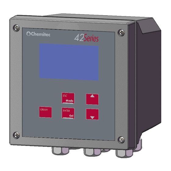
Fish farm • Primary Water, Drinking Water Figure 1 – Wall (a) and panel (b) mounting Conductivity analyzer (4222) MEASURING PRINCIPLES The electrical conductivity measure shows the ion concentration into a solution. More is the solution acid or even basic salt quantity, higher is the conductivity. The conductivity measuring unit is Siemens/cm. -
Page 11: Main Charactheristics
4222 DISSOLVED CONDUCTIVITY AND TEMPERATURE ANALYZER TECHNICAL MANUAL P/N XXX-0000 Rev.1 Ver.2.2 α [1 + (T - 20)] where: = conductivity to the temperature T = conductivity at 20°C = solution temperature α = T coefficient at 20°C in % / °C The α... -
Page 12: Technical Characteristics For Conductivity (Primary Measure)
4222 DISSOLVED CONDUCTIVITY AND TEMPERATURE ANALYZER TECHNICAL MANUAL P/N XXX-0000 Rev.1 Ver.2.2 • Internal Data Logger (flash 4 Mbit) with the possibility of graphic and table visualisation of measurement trends • PID adjustment • Serial outlet RS485 MOD BUS RTU •... - Page 13 4222 DISSOLVED CONDUCTIVITY AND TEMPERATURE ANALYZER TECHNICAL MANUAL P/N XXX-0000 Rev.1 Ver.2.2 0 ÷ 2000 µS – 00.00÷20.00mS ON – OFF Time 000 ÷ 999 Seconds For every digital output a relay with contacts opened normally is used. The maximum current commutable is...
-
Page 14: Controls, Indicators And Connections
4222 DISSOLVED CONDUCTIVITY AND TEMPERATURE ANALYZER TECHNICAL MANUAL P/N XXX-0000 Rev.1 Ver.2.2 CONTROLS, INDICATORS AND CONNECTIONS Figure 2 – Wall instrument, front panel 1. Visualizer with LCD Display 2. UP key 3. ESC key 4. ENTER key 5. DOWN key 6. -
Page 15: Graphic Display
4222 DISSOLVED CONDUCTIVITY AND TEMPERATURE ANALYZER TECHNICAL MANUAL P/N XXX-0000 Rev.1 Ver.2.2 GRAPHIC DISPLAY The graphic display allows for visualization of the various programming menus and, in the measuring method (RUN), visualization of the measurements and of the state of operation. -
Page 16: Division Of The Graphical Display Into Areas In The Run Method
4222 DISSOLVED CONDUCTIVITY AND TEMPERATURE ANALYZER TECHNICAL MANUAL P/N XXX-0000 Rev.1 Ver.2.2 2.4.2 DIVISION OF THE GRAPHICAL DISPLAY INTO AREAS IN THE RUN METHOD Figure 4 – Graphic display - divided up into areas In the following table, for every area of the display indicated in figure 3, the symbols that may appear during functioning of the device in a measurement method (RUN) are represented and briefly described. - Page 17 4222 DISSOLVED CONDUCTIVITY AND TEMPERATURE ANALYZER TECHNICAL MANUAL P/N XXX-0000 Rev.1 Ver.2.2 GRAPHIC VISUAL REPRESENTATION DESCRIPTION ZONE Stay time Probe frozen on a value Maximum Logical Set Exceeded Minimum Logical Set Exceeded Maximum dosage time exceeded Washing stage active Value outlet n.1 (in mA) Value outlet n.2 of temperature (in mA)
- Page 18 4222 DISSOLVED CONDUCTIVITY AND TEMPERATURE ANALYZER TECHNICAL MANUAL P/N XXX-0000 Rev.1 Ver.2.2 GRAPHIC VISUAL REPRESENTATION DESCRIPTION ZONE 20% of the scale 30% of the scale 40% of the scale 50% of the scale 60% of the scale 70% of the scale...
-
Page 19: Installation
TECHNICAL MANUAL P/N XXX-0000 Rev.1 Ver.2.2 INSTALLATION Although the unit is suitable for installation in outdoor environments, it is recommended to avoid direct exposure to sun and weather. Before installing the 4222 carefully read the instructions provided below. COMPOSITION OF THE SUPPLY The supply consists of just one package which contains the following parts: •... -
Page 20: Installation Of 96X96 Electrical Panel Device
The thickness of the panel must not exceed 5 mm. The perforation DIMA must comply with the following layout: Figure 6 – Encumbrance and Dima for perforation of the panel Mechanical Dimensions 4222 96x96 Panel Mounted 96x96x115,5 mm Dimensions (L x H x P) 130mm... -
Page 21: Installation Of 144X144 Electrical Panel Device
The thickness of the panel must not exceed 5 mm. The perforation DIMA must comply with the following layout: Figure 8 – Encumbrance and Dima for perforation of the panel Mechanical Dimensions 4222 144x144 Panel Mounted 144x144x86,5mm Dimensions (L x H x P) 70mm... -
Page 22: Electrical Connections To The Dosage Systems (Users)
4222 CONDUCTIVITY AND TEMPERATURE ANALYZER TECHNICAL MANUAL P/N XXX-0000 Rev.1 Ver.2.2 In any case it is always best to check the quality of the Ground connection. It is very common to find Ground connections, mainly in industrial environments, that are generators themselves of disturbances: in the case of any doubts on quality a connection to a rod dedicated to the device plant is recommended. -
Page 23: 3.1.4.1.1 Connection Terminal Box For Wall Mounted 4222
4222 CONDUCTIVITY AND TEMPERATURE ANALYZER TECHNICAL MANUAL P/N XXX-0000 Rev.1 Ver.2.2 3.1.4.1.1 Connection terminal box for wall mounted 4222 Figure 10 Connections terminal box (wall mounted) CLAMP Nr. GRAPHIC DESCRIPTION Power supply (Earth) Power supply (Neutral) Power supply (Phase) Probe Supply (+12V) -
Page 24: 3.1.4.1.2 Connection Terminal Box For Panel Mounted 4222
4222 CONDUCTIVITY AND TEMPERATURE ANALYZER TECHNICAL MANUAL P/N XXX-0000 Rev.1 Ver.2.2 3.1.4.1.2 Connection terminal box for panel mounted 4222 Figure 11 Connections terminal box (panel mounted) CLAMP Nr. GRAPHIC DESCRIPTION Power supply (Earth) Power supply (Neutral) Power supply (Phase) Probe Supply (+12V) -
Page 25: 3.1.4.2 Connections To The Power Supply
4222 CONDUCTIVITY AND TEMPERATURE ANALYZER TECHNICAL MANUAL P/N XXX-0000 Rev.1 Ver.2.2 CLAMP Nr. GRAPHIC DESCRIPTION Driving 2 (4 wires) Signal 2 Return (4 wires) Signal 1 Return (4 wires) Driving 1 (4 wires) NTC / PT100 / PT1000 Common Cable... -
Page 26: Methods Of Use
4222 CONDUCTIVITY AND TEMPERATURE ANALYZER TECHNICAL MANUAL P/N XXX-0000 Rev.1 Ver.2.2 METHODS OF USE COMPOSITION OF THE MEASURING SYSTEM 4.1.1 MINIMUM CONFIGURATION Figure 12 Minimum configuration 4.1.2 MAXIMUM CONFIGURATION Figure 13 Maximum Configuration... -
Page 27: Start Up Of The System
0% and the display will be completely white. In order to reset the correct level, simply press the UP key to the desired value. Using the UP and DOWN keys it is possible to adjust the contrast percentage. 220V DOWN COND 4222 Contrast Control Ver 1.0 WAIT… ENTER 1.0 mS... -
Page 28: Setup Menu (Temperature - System Setup)
4222 CONDUCTIVITY AND TEMPERATURE ANALYZER TECHNICAL MANUAL P/N XXX-0000 Rev.1 Ver.2.2 By pressing the ESC key the screen will go back to the menu or to the previous function and any variations made will be cancelled. 4.3.1 SETUP MENU (TEMPERATURE – SYSTEM SETUP) - Page 29 4222 CONDUCTIVITY AND TEMPERATURE ANALYZER TECHNICAL MANUAL P/N XXX-0000 Rev.1 Ver.2.2 A2) Setup System In this part of the programme which is divided up into 5 functions, the basic functioning parameters of the instrument are set. Description of the functions:...
-
Page 30: Setup Menu (Digital Input - Select Measure)
4222 CONDUCTIVITY AND TEMPERATURE ANALYZER TECHNICAL MANUAL P/N XXX-0000 Rev.1 Ver.2.2 4.3.2 SETUP MENU (DIGITAL INPUT – SELECT MEASURE) ENTER + DOWN 1. 0 SETUP 1. 0 SETUP Temperature Temperature Setup System Setup System Digital input Digital Input DOWN Select measure... - Page 31 4222 CONDUCTIVITY AND TEMPERATURE ANALYZER TECHNICAL MANUAL P/N XXX-0000 Rev.1 Ver.2.2 • 0-200 mS • 0-20 mS • 0-2000 µS • 0-200 µS • 0-20 µS If the measuring unit is Siemens and the constance cell is 0,1, range is selectable between: •...
-
Page 32: Outputs Menu (Relay Outputs - Set Point 1)
4222 CONDUCTIVITY AND TEMPERATURE ANALYZER TECHNICAL MANUAL P/N XXX-0000 Rev.1 Ver.2.2 D2) Constance cell Allows to set the value of the della Constance cell, choosing between 0.1, 1, 10 and 100. D3) Measur. Unit This menu is only selectable if the invoice “TDS” in the “Select Measure” menu (C1) is selected and allows to set the measuring unit of the TDS;... - Page 33 4222 CONDUCTIVITY AND TEMPERATURE ANALYZER TECHNICAL MANUAL P/N XXX-0000 Rev.1 Ver.2.2 Measure Figure 15 – Threshold operation Furthermore by acting on the Time ON and Time OFF parameters it is possible to define a DELAY time or a TIMED operation of the Relay during its activation.
- Page 34 4222 CONDUCTIVITY AND TEMPERATURE ANALYZER TECHNICAL MANUAL P/N XXX-0000 Rev.1 Ver.2.2 E2) PID-PWM By defining the Set Point as PID-PWM, through Relay 1, it is possible to activate a pump with an ON/OFF command almost as if it had a proportional adjustment. For this function the time period must be programmed (in seconds) within which the calculation of the PWM adjustment will come about.
-
Page 35: Outputs Menu (Relay Outputs - Set Point 2, Etc.)
4222 CONDUCTIVITY AND TEMPERATURE ANALYZER TECHNICAL MANUAL P/N XXX-0000 Rev.1 Ver.2.2 4.3.5 OUTPUTS MENU (RELAY OUTPUTS – SET POINT 2, ETC.) 2.0 OUTPUT ENTER ENTER Relay Outputs B1) Set Point2 Current Output Setup PID DOWN UP/DOWN UP/DOWN UP/DOWN (F1) (F2) - Page 36 4222 CONDUCTIVITY AND TEMPERATURE ANALYZER TECHNICAL MANUAL P/N XXX-0000 Rev.1 Ver.2.2 SET RELEASE With this function it is possible to deactivate or activate dosages in the case of an alarm. By programming YES, when any kind of alarm is activated, the Relay 1 and 2 contacts will open up immediately and the analogical outlets 1 and 2 will be cancelled.
-
Page 37: Outputs Menu (Set Point Temp.)
4222 CONDUCTIVITY AND TEMPERATURE ANALYZER TECHNICAL MANUAL P/N XXX-0000 Rev.1 Ver.2.2 INTERVAL With this function it is possible to set the interval of time between one washing stage and the next. Immediately before it starts, the instrument memorizes the values of the measurements, the state of Relay 1 and 2 and the values of the analogical outlets and it keeps them “frozen”... -
Page 38: Outputs Menu (Current Output)
4222 CONDUCTIVITY AND TEMPERATURE ANALYZER TECHNICAL MANUAL P/N XXX-0000 Rev.1 Ver.2.2 4.3.7 OUTPUTS MENU (CURRENT OUTPUT) (H1) (H2) 2.0 USCITA 2.2 CURRENT OUTPUT 2.2 CURRENT OUTPUT Measure Measure Relay Outputs Second Output Second Output Current Output ENTER Setup PID ENTER... -
Page 39: Outputs Menu (Setup Pid)
4222 CONDUCTIVITY AND TEMPERATURE ANALYZER TECHNICAL MANUAL P/N XXX-0000 Rev.1 Ver.2.2 The second output can be set as Temperature, Auxiliary or PID. If set as Temperature a Range between 0-20mA or 4-20mA can be chosen, the Lower and Upper limits of the Temperature value. For a detailed description of how to set them, refer to point 5.1 Measuring of Analogical Outlet. -
Page 40: Calibrations Menu
4222 CONDUCTIVITY AND TEMPERATURE ANALYZER TECHNICAL MANUAL P/N XXX-0000 Rev.1 Ver.2.2 The type of algorithm will be chosen according to the application requested. The P regulation will be set as a default. THE ALGORITHM SIGN In this function the PID sign is programmed. If we programme DIRECT it means that as the value measured is increased compared with the threshold defined, the PID value will decrease. -
Page 41: Conductivity Calibration
4222 CONDUCTIVITY AND TEMPERATURE ANALYZER TECHNICAL MANUAL P/N XXX-0000 Rev.1 Ver.2.2 Descriptions of the calibration functions: 3.0 CALIBRATIONS 3.0 CALIBRATIONS Conductivity Conductivity ENTER Temp Temp DOWN From this menu it is possible to choose the type of calibration: Conductivity or Temperature 4.3.9.1 Conductivity calibration... -
Page 42: Temperature Calibration
4222 CONDUCTIVITY AND TEMPERATURE ANALYZER TECHNICAL MANUAL P/N XXX-0000 Rev.1 Ver.2.2 J1) Automatic system The conductivity calibration foresees two calibration points. J.1.1) The first calibration must be done at 0µS !! After inputting the temperature compensation value (if the conductivity probe is temperature compensated, the temperature value will be read automatically) press ENTER key and dip the probe into a solution at 0µS or expose it to air after... -
Page 43: Archive Menu
4222 CONDUCTIVITY AND TEMPERATURE ANALYZER TECHNICAL MANUAL P/N XXX-0000 Rev.1 Ver.2.2 K1) Automatic Calibration The calibration consists in adding or subtracting an offset in order to bring back the value given by the instrument to the correct measure. K2) Reset Default... -
Page 44: Measuring Graphics Menu
4222 CONDUCTIVITY AND TEMPERATURE ANALYZER TECHNICAL MANUAL P/N XXX-0000 Rev.1 Ver.2.2 Last Data >>> You will start by examining the archive of the last data stored and move backwards Date/Time>>> You will start by examining the archive from a specific date and time In order to move backwards and forwards use the UP and DOWN keys and once you reach the first or last data it will stop. -
Page 45: Manual Control Menu
4222 CONDUCTIVITY AND TEMPERATURE ANALYZER TECHNICAL MANUAL P/N XXX-0000 Rev.1 Ver.2.2 The Times item indicates for how many hours we want to visualise the drawing. The default is 1 hour but we can choose from 1, 6 or 24 hours. -
Page 46: Functions In Run
4222 CONDUCTIVITY AND TEMPERATURE ANALYZER TECHNICAL MANUAL P/N XXX-0000 Rev.1 Ver.2.2 CAUTION When exiting from the “MANUAL CONTROL” function, all the possible manual settings will be reset. 4.3.13 FUNCTIONS IN RUN (N1) 1.0 mS (N2) EDITING RUN Set Point Set Point... - Page 47 4222 CONDUCTIVITY AND TEMPERATURE ANALYZER TECHNICAL MANUAL P/N XXX-0000 Rev.1 Ver.2.2 In the RUN screen the following things can be seen: • Dissolved Conductivity measure • Percent value compared to full scale (bargraph) • the status and type of programming of Relays 1 and 2 •...
-
Page 48: User Maintenance
4222 CONDUCTIVITY AND TEMPERATURE ANALYZER TECHNICAL MANUAL P/N XXX-0000 Rev.1 Ver.2.2 USER MAINTENANCE SPECIAL CAUTIONS FOR CRITICAL COMPONENTS An LCD (Liquid Crystal Display) is incorporated into the equipment and it contains small amounts of toxic materials. In order to avoid damages to people and to limit the negative effects on the environment, comply... -
Page 49: Modbus Protocol
4222 CONDUCTIVITY AND TEMPERATURE ANALYZER TECHNICAL MANUAL P/N XXX-0000 Rev.1 Ver.2.2 MODBUS PROTOCOL Main features • Protocollo MODBUS standard tipo RTU • Layer fisico: RS485 a due fili (half-duplex) • Layer fisico alternativo: USB • 8 bit, Parità N, 1 Stop bit •... - Page 50 4222 CONDUCTIVITY AND TEMPERATURE ANALYZER TECHNICAL MANUAL P/N XXX-0000 Rev.1 Ver.2.2 22 Set Min (set_min) 24 Limite basso Analog Out 1 (Misura Principale) (clim1_low) 26 Limite alto Analog Out 1 (Misura Principale) (clim1_high) 28 Limite basso Analog Out 2 (Misura Principale / Temperatura) (clim2_low)
- Page 51 4222 CONDUCTIVITY AND TEMPERATURE ANALYZER TECHNICAL MANUAL P/N XXX-0000 Rev.1 Ver.2.2 04 Flag per tipo di Temperatura (0=°C, 1=°F) (fahren_flag) 05 Segno Algoritmo PID (0=Diretta, 1=Inversa) (pid_cnsgn) 06 Logica Relè Allarme in ON (0=Chiuso, 1=Aperto) (alrlog_flag) 07 Funzionamento Analog Out 2 (0=Proporzionale, 1=PID) (pid2_flag)
- Page 52 4222 CONDUCTIVITY AND TEMPERATURE ANALYZER TECHNICAL MANUAL P/N XXX-0000 Rev.1 Ver.2.2 94 Periodo del PWM max 999 sec (set1_pid_period) 96 MAX Frequenza imp/h (max. 7200 regolazione a 200 step)(set1_pid_freq) Scarico archivi a blocchi di record Sequenza: 1. Richiesta lunghezza singolo record.
- Page 53 4222 CONDUCTIVITY AND TEMPERATURE ANALYZER TECHNICAL MANUAL P/N XXX-0000 Rev.1 Ver.2.2 Richiesta numero record presenti (con reset del puntatore) Richiesta Byte Descrizione Numero Slave Periferica BHIST_ARC_FN = 0x44 (Funzione) BHIST_ARC_NUM_REC = 0x03 (Sottofunzione) CRC (lo) CRC (hi) Risposta Byte Descrizione...
- Page 54 4222 CONDUCTIVITY AND TEMPERATURE ANALYZER TECHNICAL MANUAL P/N XXX-0000 Rev.1 Ver.2.2 Risposta Byte Descrizione Numero Slave Periferica BHIST_ARC_FN = 0x44 (Funzione) BHIST_ARC_BLOCK_NEXT = 0x05 (Sottofunzione) Lunghezza Dati (lo) Lunghezza Dati (hi) Dati … CRC (lo) CRC (hi) Se Lunghezza Dati=0 : si è richiesto un record oltre il numero di record...
- Page 55 4222 CONDUCTIVITY AND TEMPERATURE ANALYZER TECHNICAL MANUAL P/N XXX-0000 Rev.1 Ver.2.2 (*) Bit di Stato Relè bit0 = RL0 (Set Point 1) bit1 = RL1 (Set Point 2) bit2 = RL2 (Allarme / Set Point Temperatura 2) bit3 = RL3 (Wash / Set Point Temperatura 1)
-
Page 56: Warranty
TECHNICAL MANUAL P/N XXX-0000 Rev.1 Ver.2.2 WARRANTY Chemitec s.r.l. will replace or repair at its own sole option, those parts that may eventually manifest defects in manufacturing or operating, despite of a diligent and proper use by the customer. The defective product, or considered such, must be sent free of charge to the Chemitec Factory, via I. -
Page 57: Request For Assistance
In the case of a fault to the equipment or in the case of partial or incorrect functioning that cannot be resolved through the ordinary maintenance operations described in this manual or in the documentation attached, we kindly ask you to contact a CHEMITEC office or branch or your nearest dealer or authorised assistance centre.
Need help?
Do you have a question about the 4222 and is the answer not in the manual?
Questions and answers