Table of Contents
Advertisement
Advertisement
Table of Contents

Related Manuals for RS PRO RSPD3303C


Summary of Contents for RS PRO RSPD3303C
- Page 1 Quick Start RSPD3303C Programmable DC Power Supply...
-
Page 2: General Safety Summary
General Safety Summary Please review the following safety precautions carefully to avoid personal injury or damage to this product or any product connected to it. To prevent potential danger, please use the instrument as specified. Use proper power cord Only the power cord designed for the instrument and authorized by local country could be used. - Page 3 Keep proper ventilation Inadequate ventilation may cause an increase of temperature, which will lead to further damage. Please keep proper ventilation and check the fan and air-vents regularly when using the instrument. Operate condition Location: indoor, no strong light, almost no Interfering pollution Comparative humidity: <80% Altitude: <2000m Temperature: 0℃...
-
Page 4: Safety Terms And Symbols
Safety Terms and Symbols Terms may appear on the product: DANGER: Indicates direct injury or hazard that may happen. WARNING: Indicates potential injury or hazard that may happen. CAUTION: Indicates potential damage to the instrument or other property that may happen. Symbols may appear on the product: Hazardous Protective... -
Page 5: Brief Introduction
Brief Introduction RSPD3303C LED series Programmable DC Power Supply is convenient, flexible and multi-function. It is designed with three groups of independent output terminals, the output voltage of two groups is adjustable and another group is fixed to select: 2.5V, 3.3V, and 5V. -
Page 6: Chapter 1 Quick Guide
Chapter 1 Quick Guide In this chapter, we mainly introduce the panel display interface and inspecting the new machine. Reading the following steps will give you a quick understanding on operation. General Inspection 1. Inspect the shipping container. Keep the damaged shipping container or cushioning material until the contents of the shipment have been completely checked and the instrument has passed both electrical and mechanical tests. -
Page 7: Safety Considerations
RSPD3303C. Input Power Requirement The RSPD3303C allows a 50Hz/60Hz frequency, and four levels of AC power: 100V/120V/220V/230V. You can select required power voltage with the “DIP Switch ” at the rear panel according to the actual demand. -
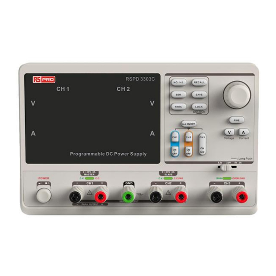
Page 8: The Front Panel
The Front Panel Description Description Logo CH3 DIP Switch LED Display Power Switch Model CH1 Output Terminal Configuration button Ground Terminal Multi-function knob CH2 Output Terminal Fine Adjust button CV/CC Indicator Light Voltage/Current button CH3 Output Terminal Channel Control button... -
Page 9: Instruction For Buttons
Instruction for Buttons Buttons for setting parameters NO.1- 5 : Press the button to choose the storage location : Press the button to set series mode of CH1/CH2. PARA : Press the button to set parallel mode of CH1/CH2. LOCK : Long press the button to turn on/off the keylock function. -
Page 10: The Front Panel Terminals
The Front Panel Terminals The positive/negative output terminals of CH1, CH2, CH3, and the common GND for CH1, CH2 are located on the front panel. Refer to later “control panel operation” for wiring method details. -
Page 11: User Interface
User Interface 1: Channel Logo 2 : Voltage set/Readback value 3 : Current set/Readback value... - Page 12 The Rear Panel Description: Warning message AC power DIP switch Instruction for the AC input voltage AC power socket Fan vent CE certification mark USB interface...
-
Page 13: Output Checking
Output Checking To ensure the instrument is operating correctly, please check the output voltage and current before load is connected. 1. Output voltage checking (1) With the instrument no load, turn on the power, and make sure the current value displaying is not zero (2) Check the output voltage of CH1/CH2 Turn on CH1/CH2 channel and the instrument will work in CV mode. -
Page 14: Chapter 2 Control Panel Operation
Chapter 2 Control Panel Operation n this chapter,the function and operation of RSPD3303C control panel will be introduced in detail to give you an all-around understanding of it. Brief introduction Output Summary CH1/CH2 Independent Output CH3 Independent Output Parallel Output... -
Page 15: Output Summary
Output Summary RSPD3303C is designed with three independent outputs, two of which are adjustable in voltage value and the other includes a set of selectable voltage values: 2.5V, 3.3V or 5.0V. Independent/Parallel/Series RSPD3303C has three output modes: independent, parallel and series that could be selected through the track switch on the front panel. -
Page 16: Ch1/Ch2 Independent Output
CH1/CH2 Independent Output Instruction CH1 and CH2 are working in independent mode and insulated from the ground. Output ratings 0~30V/0~3A (Max: 32V, 3.2A) Operation steps 1. Make sure that parallel/series mode is off. 2. Connect load to the positive and negative terminals of CH1/CH2. 3. -
Page 17: Ch3 Independent Mode
CH3 Independent mode Instruction CH3 works independently from CH1, CH2, and its voltage and current ratings are: 2.5V, 3.3V, 5V, 3A. Output ratings 2.5V/3.3V/5V, 3A Operation steps: 1. Connect the load to the positive and negative terminal of CH3 channel. 2. -
Page 18: Ch1/Ch2 Series Mode
CH1/CH2 Series Mode Instruction:In the series mode, CH1 and CH2 are linked internally into one channel controlled by CH1. The output voltage value is twice compared with that of single channel. Output ratings 0~60V/0~3A (Max: 64V, 3.2A) Operation steps: 1. Press the SER to start the Series mode, and the indicator light turns bright 2. -
Page 19: Ch1/Ch2 Parallel Mode
CH1/CH2 Parallel Mode Instruction In the parallel mode, CH1 and CH2 are linked internally into one channel controlled by CH1. The output current value is twice as much as the single channel. Output ratings 0~30V/0~6A (Max: 32V, 6.4A) Operation steps: 1. -
Page 20: Save And Recall
Save and Recall Five groups of setups can be saved in memory. Contents of setups including: Independent/series/parallel mode Output voltage/current value Steps for saving setup 1. Set the state needed to save 2. Press SAVE to enter the save interface 3. -
Page 21: Version Upgrade
Version Upgrade The software of the instrument is upgraded with a fixed name file via PC management software with USBTMC. The upgrade method is below: Upgrade in normal Interface 1. Open the EasyPower software after correct connection of the USB cable with the instrument. 2. - Page 22 Figure 2 Figure 3 4. As shown in figure 4, click “Upgrade” to start upgrading. The instrument will run the upgraded software as soon as the upgrading completed. Figure 4...
- Page 23 Upgrade via the Guiding Procedure Upgrading via the guiding procedure can be used if the previously detailed method failed. Specific steps: 1. Press the power button to start the instrument, and it will enter the guide procedure mode. 2. As illustrated in figure 2, select the “Firmware Mode” option instead , then follow the upgrade steps detailed previously.
-
Page 24: Chapter 3 Remote Control
Chapter 3 Remote Control SCPI Commands can be used to conduct remote control on the RSPD3303C Power Supply through the USBTMC. To utilise the remote control, the installation of EasyPower or NI(Measurement & Automation ) software is required prior to connecting the instrument with a USB cable. -
Page 25: Command Description
Query the manufacturer, product model, series NO. and software version. Return Info Manufacturer, product model, series NO., software version. Example RSPD3303C, SPD00001130025, .01.01.02. 2.*SAV Command format *SAV <name> Description Save the current state in nonvolatile memory with the specified name. - Page 26 4. INSTrument Command format INSTrument <CH1|CH2> Description Select the channel that will be operated. Example INSTrument CH1 Command format INSTrument? Description Query the current operating channel Example INSTrument? Return Info 5. MEASure Command format MEASure: CURRent? < CH1|CH2> Description Query current value for specified channel, if there is no specified channel, query the current channel.
- Page 27 6. SOURce Command format <SOURce:>CURRent <value> <SOURce>:={CH1 | CH2} Description Set current value for the current channel Example CH1:CURRent 0.5 Command format <SOURce>: CURRent? <SOURce>:={CH1 | CH2} Description Query the current value for the current channel. Example CH1: CURRent? Return Info Command format <SOURce>: VOLTage <value>...
- Page 28 7. OUTPut Command format OUTPut <SOURce>, <state> <SOURce>:={CH1 | CH2} <state>:={ON | OFF} Description Turn on/off the specified channel. Example OUTPut CH1, ON Command format OUTPut: TRACK <NR1> <NR1>:={0[Independent] | 1[Series] | 2[Parallel]} Description Select the operation mode Example OUTPut: TRACK 0 8.
- Page 29 Command format SYSTem: STATus? Description Query the current working state. Example SYSTem: STATus? Return info 0x0224 Instruction The return info is in Hexadecimal format, which means that you must translate the return info into binary format. The correspondence relationship is as shown below. Bit NO.
-
Page 30: Specification
Specification Test conditions: warm-up for about 30minitus, with temperature between +20℃~+30℃. Output CH1/CH2 independent 0~30V , 0~3A Ratings CH1/CH2 series 0~60V , 0~3A CH1/CH2 parallel 0~30V , 0~6A 2.5V/3.3V/5.0V , 0~3A ≤0.01%+3mV power change rate Constant ≤0.01%+3mV(rating current ≤ 3A) Voltage Mode Load change rate ≤0.02%+5mV(rating current >... - Page 31 Operating Indoor ≤2000 m environment Altitude Environment temperature 0 ~ 40℃ Comparative humidity Ⅱ Installation level Pollution level Storage Environment temperature -10 ~ 70℃ ≤ 70% environment Comparative humidity Power supply AC 100V/120V/220V/230V± 10%, 50/60HZ Volume 275mm x 225mm x 136mm Weight 7.5kg...
Need help?
Do you have a question about the RSPD3303C and is the answer not in the manual?
Questions and answers