Table of Contents
Advertisement
DC POWER SUPPLY
ALIMENTATION C.C.
ISO-TECH
ISO-TECH
SAFETY TERMS AND SYMBOLS
These terms may appear in this manual or on the product:
The following symbols may appear in this manual or on the product:
DANGER
High Voltage
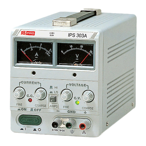
IPS 303A
IPS 601A
WARNING. Warning statements identify conditions or practices that
could result in injury or loss of life.
CAUTION. Caution statements identify conditions or practices that could
result in damage to this product or other property.
DANGER
ATTENTION
Hot Surface
refer to Manual
201-3424
201-3446
Protective
Equipotentiality
Conductor
Terminal
Advertisement
Table of Contents

Related Manuals for RS PRO Iso-tech IPS 303A


Summary of Contents for RS PRO Iso-tech IPS 303A
- Page 1 DC POWER SUPPLY ALIMENTATION C.C. ISO-TECH IPS 303A 201-3424 ISO-TECH IPS 601A 201-3446 SAFETY TERMS AND SYMBOLS These terms may appear in this manual or on the product: WARNING. Warning statements identify conditions or practices that could result in injury or loss of life. CAUTION.
- Page 2 FOR UNITED KINGDOM ONLY NOTE As the colours of the wires in main leads may not correspond with the colours marking This lead/appliance must only Identified in your plug/appliance, proceed as follows: be wired by competent persons The wire which is coloured Green & Yellow must be connected to the Earth terminal WARNING THIS APPLIANCE MUST BE marked with the letter E or by the earth symbol...
-
Page 3: Table Of Contents
CONTENTS SECTION PAGE INTRODUCTION… … … … … … … … … … … … … … … … … … … … … … … … … … … … … .… … … … … … … … … 1 SPECIFICATIONS…... -
Page 4: Introduction
1. INTRODUCTION The regulated DC power supply has been designed to provide the most often used features in the laboratory, schools and production lines. The output voltage is continuously adjustable between 0 and rated voltage in one range by means of a coarse and fine potentiometer;... -
Page 5: Specifications
2. SPECIFICATIONS 2-1 General Main supply : 100V/120V/220V/230V±10% 50/60Hz (Switch selectable). Rating, dimension and weight : see Table 2-1 Operation mode : Single or Tracking (Series or Parallel) operation (two units). Operation Temperature & Humidity : 0ºC to 40ºC, <80% Storage Temperature &... -
Page 6: Constant Voltage Operation
2-2 Constant Voltage Operation (1) Output voltage ranges 0 to rating voltage continuously adjustable. (2) Voltage regulation line regulation ∗0.01%+3mV. load regulation ∗0.01%+3mV (rating current ∗3A). load regulation ∗0.01%+5mV (rating current >3A). (3) Recovery time ∗100µs (50% Load change, minimum load 0.5A). (4) Ripple &... -
Page 7: Panel Controls And Indicators
3. PANEL CONTROLS AND INDICATORS 3-1 Front panel (See Fig. 3-1) CV Indicator lights when the power is on and this unit is in constant voltage operation. CC Indicator lights when this unit is in constant current operation. Voltage coarse for the coarse adjustment of the output voltage. - Page 8 FIG. 3-1 Front Panel...
- Page 9 FIG. 3-2 Rear Panel...
-
Page 10: Operation Instructions
4. OPERATION INSTRUCTIONS 4-1 Precaution (1) AC input AC input should be within the range of line voltage ±10% 50/60Hz. WARNING. To avoid electrical shock, the power cord protective grounding conductor must be connected to ground. (2) Installation Avoid using the power supply in a place where the ambient temperature exceeds 40ºC. The heat sink located at the rear of the power supply must have sufficient air space for radiation. - Page 11 indicator goes off and the CC indicator comes on. Fig. 4-1 Constant Voltage/Constant Current Characteristic Similarly, crossover from the constant current to the constant voltage mode automatically occurs from a decrease in load. A good example of this would be seen when charging a 12-volt battery. Initially, the open circuit voltage of the power supply may be preset for 13.8 volts.
-
Page 12: Operation Mode
4-4 Operation Mode (1) Single Operation Use the supply as it is for single operation. A. Set power switch to “OFF” position. B. Make sure that line voltage is correct for the input power voltage. C. Plug power cord into the power outlet. D. - Page 13 Fig. 4-2 Connecting Two Power Supplies in Series...
- Page 14 E. When connected in series, the VOLTAGE controls of each power exercise control supply over 0 to rating range. Add the two voltmeter readings together to determine the total output voltage, or an external voltmeter may be connected across the load. F.
- Page 15 Fig. 4-3 Connecting Two Power Supplies in Parallel...
- Page 16 (4) Remote control of output voltage The output voltage of the power supply can be remote-controlled with an external voltage; the connection required is shown in Fig. 4-4. l Fig. 4-4 A. Set the power supply INT-SLAVE switch to “SER-SLAVE” position. B.
- Page 17 (5) Remote control of output current The output current of the power supply can be remote-controlled with an external voltage; the connection required is shown in Fig. 4-5. l Fig. 4-5 A. Set the power supply INT-SLAVE switch to “PAR-SLAVE” position. B.
-
Page 18: Maintenance
5. MAINTENANCE WARNING The following instructions are for use by qualified personnel only. To avoid electrical shock, do not perform any servicing other than contained in the operating instructions unless you are qualified to do so. 5-1 Fuse Replacement If the fuse is blown, the CV or CC indicators will not light and the power supply will not operate. The fuse should not normally blow unless a problem has developed in the unit. -
Page 19: Cleaning
If readjustment is required, use the following procedure. Locations of the adjustments are shown in Fig. 5-1 and Fig. 5- (1) Adjustment of the Rating Voltage A. Connect an accurate (±0.1%) external multimeter to measure the DC voltage at output terminals of the power supply. - Page 20 Fig. 5-1 Adjustment Location...
- Page 21 Fig. 5-2 Adjustment Location...
Need help?
Do you have a question about the Iso-tech IPS 303A and is the answer not in the manual?
Questions and answers