Advertisement
Quick Links
Download this manual
See also:
Instruction Manual
T
ECHNICAL INFORMATION
Models No.
Description
C
ONCEPT AND MAIN APPLICATIONS
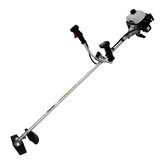
Model RBC413U is symmetric design bike handle style Petrol brushcutter
powered by 40.2 mL 2-stroke engine.
This product has been developed based on RBC411U, and Diaphragm
carburetor has been employed instead of the float type carburetor of RBC411U.
Other basic features are the same as RBC411U; therefore, the engine for
this model does not comply with well-known exhaust emission regulations.
RBC414U is asymmetric design bike handle style. The handle can be removed
quickly from drive shaft without tool. The others are the same as RBC413U.
RBC414UG is only available in Brazil for use of E25 gasoline (mixture of 25%
anhydrous ethanol and 75% gasoline.)
S
pecification
Type
Displacement: mL
Engine
Fuel
Max. output: kW (PS)
Max. torque (N·m)
Max. spindle speed at no load: min.
Compliance with main exhaust
emission regulations; CARB Tier 3,
EPA Phase 2, EU Stage 2
Carburetor
Easy start
Starting
(Spring-assisted recoil starter)
system
Decompression valve
Starting system
Fuel tank capacity: L
Primer pump
Clutch
Spindle thread size
Handle style
Net weight**: kg (lbs)
* 2 cycle engine oil is required in the correct mixture ratio.
** Dry weight, without guard, cutting tool and shoulder harness
S
tandard equipment
Blade or Nylon head .......................................................1
Wrench 17-19 ..................................................................1
Hex wrench 4 ..................................................................1
Hex wrench 5 ..................................................................1
Note: The standard equipment for the tool shown above may vary by country.
O
ptional accessories
Double blade 305mm (12"), Triple blade 255mm (10"), Triple blade 305mm (12"), Star blade 230mm (9"),
Star blade 255mm (10"), 8-tooth blade 230mm (9"), 8-tooth blade 255mm (10"), Nylon cutting head (Bump & Feed Z5L),
Nylon cutting head (Ultra Auto 6L), Protector (for cutting blade only), Universal guard (=Protector),
Universal guard extension, Safety googles, Fuel mixture
RBC413U, RBC414U, RBC414UG
Petrol Brushcutter
¹ = rpm
ˉ
Symmetric design
bike handle
RBC413U
RBC414U
2-stroke
40.2
Mixed gasoline*
1.4 (1.9) [at 7,000 min.
2.2 [at 5,000 min.
6,800
No
Diaphragm
No
No
Recoil starter
1.1
Yes
Yes
M10x1.25, Left-handed
Asymmetric design bike handle
7.1 (15.7)
Box wrench 17 ................................................................1
Shoulder strap assembly ..................................................1
Accessory bag .................................................................1
Safety goggles (for Slovenia only) ..................................1
Fuel mixture (for Vietnam only) .....................................1
W
H
RBC413U
L
Dimensions: mm (")
RBC413U
Length (L)
1,710 (67-3/8)
Width (W)
650 (25-5/8)
Height (H)
435 (17-1/8)
RBC414UG
Mixed E25 gasoline*
¹]
ˉ
¹]
ˉ
7.2 (15.9)
PRODUCT
P 1/ 17
W
L
H
RBC414U,
RBC414UG
RBC414U
630 (24-3/4)
515 (20-1/4)
Advertisement

Subscribe to Our Youtube Channel
Related Manuals for Makita RBC414U


Summary of Contents for Makita RBC414U
- Page 1 Other basic features are the same as RBC411U; therefore, the engine for this model does not comply with well-known exhaust emission regulations. Dimensions: mm (") RBC414U is asymmetric design bike handle style. The handle can be removed RBC413U RBC414U quickly from drive shaft without tool. The others are the same as RBC413U.
-
Page 2: Necessary Repairing Tools
(1) Apply 1g of Makita grease N No. 2 to Spiral spring in Recoil starter. (2) When the inside of Gear case assembly is cleaned, supply 11g of Makita grease N No. 2 from the grease inlet. (3) Apply 6g of Makita grease N No. 1 to the entire portion of Shaft complete in Shaft pipe complete. - Page 3 (3) [For RBC413U only] Remove two M6x30 Hex socket head bolts from Handle holder ass’y to separate Handle section from Shaft pipe complete. (Fig. 5) Bike handle section can be disassembled. [For RBC414U and RBC414UG only] Loosen Knob 57 to remove Handle holder from Shaft pipe complete. Bike handle section can be disassembled.
- Page 4 Gear case assembly • Ball bearing 6000ZZ must be close to Retaining ring S-10. (See Fig. 9) • When the gear room is cleaned up, apply 11g Makita grease N No.2 into Gear case assembly from the grease U-shape table inlet.
- Page 5 P 5/ 17 epair [4] DISASSEMBLY/ ASSEMBLY [4]-5. Control lever assembly ASSEMBLING See Fig. 13. (1) Hook Control cable to Throttle lever. Assemble Switch lever and Leaf spring to Switch cover. (2) Assemble Throttle lever, Lock off lever and Switch cover to Lever case L in order while setting the following parts in place: •...
- Page 6 P 6/ 17 epair [4] DISASSEMBLY/ ASSEMBLY [4]-6. Clutch DISASSEMBLING Note: • Clutch can be easily removed with Impact driver without holding the piston. • Do not remove Spark plug as compressed air resistance has to be used for the disassembling. •...
- Page 7 P 7/ 17 epair [4] DISASSEMBLY/ ASSEMBLY [4]-7. Clutch drum complete DISASSEMBLING (1) Remove M6x14 Hex head bolt and Flat washer 6 from Clutch drum complete while inserting 783223-2 into Gear case assembly and pretighten Receive washer and Clamp washer with M10 Nut to prevent the rotation of Shaft complete.
- Page 8 P 8/ 17 epair [4] DISASSEMBLY/ ASSEMBLY [4]-7. Clutch drum complete (cont.) ASSEMBLING (1) After putting Retaining ring R-35 on the center of Clutch drum complete, pressfit Ball bearing 6003LLU in place of Clutch drum complete with 1R028. (Fig. 27) Fit Retaining ring S-17 into the groove of Clutch drum complete with 1R004.
- Page 9 P 9/ 17 epair [4] DISASSEMBLY/ ASSEMBLY [4]-8. lgnition CHECK OF PLUG CAP (SPRING) (1) Remove Plug cap from Spark plug, then detect the continuity between Plug cap spring in Plug cap and Earth terminal of Ignition coil. It is the normal condition when Tester shows 2.45kΩ±10%. (Fig. 30) (2) In case of no continuity or unstable continuity, check the connection between Plug cap spring and Ignition coil as follows: (A) Spray the lubricant in Plug cap, then pull out Plug cap spring together with Ignition cable using Pliers.
- Page 10 P 10/ 17 epair [4] DISASSEMBLY/ ASSEMBLY [4]-8. Ignition (cont.) REMOVING OF IGNITION COIL (1) Remove M5x50 Hex socket head bolt, two M5x22 Hex socket head bolts and four M5x14 Pan head screws, and then separate Blower housing, Muffler cover and Cylinder cover from the machine. (Figs. 34 and 35) (2) Before removing Ignition coil, pull out Cable terminal.
- Page 11 P 11/ 17 epair [4] DISASSEMBLY/ ASSEMBLY [4]-9. Flywheel Note: • Flywheel can be easily removed with Impact driver without holding the piston. • Do not remove Spark plug as compressed air resistance in Cylinder has to be used for the disassembling. •...
- Page 12 - Rewind the spring counterclockwise toward the center of circle. (Fig. 43) Hook in Reel (2) Apply a little amount of Makita grease N No.2 to the spring. for Spiral spring (3) Make a knot on the new rope end and pass it through Reel and Base of Starter case assembly, then connect the other end to Starter knob.
- Page 13 P 13/ 17 epair [4] DISASSEMBLY/ ASSEMBLY [4]-11. Air cleaner assembly, Carburetor REPLACING OF AIR CLEANER ASSEMBLY AND CARBURETOR Fig. 47 See Fig. 47 for all the components of Air cleaner assembly and Carburetor assembly Carburetor assembly. Do the following steps to disassemble them and replace the broken parts. (1) Slide Cleaner cover clip upward, and push the sides of Air cleaner M3x10 Pan head screw cover then remove the tab from Air cleaner housing.
- Page 14 • Set Carburetor gasket in place so that the projection faces to the bottom side of Engine. (Fig. 50) • Some specifications employ High speed needle. (Ask Makita authorized service center.) If yes, tighten the needle to the full. After that, unscrew the needle one and five eighth turns. This is the starting position to do fine adjustment.
- Page 15 P 15/ 17 epair [4] DISASSEMBLY/ ASSEMBLY [4]-13. Engine block Fig. 53 DISASSEMBLING (1) It is highly recommended to drain the oil system of Engine block before starting disassembling because the oil remaining there will drip out to delay your operation. (2) From the engine section, remove the following parts: Cylinder cover, Fuel tank, Blower housing, Muffler cover, Recoil starter Cylinder...
- Page 16 P 16/ 17 epair [5] Tightening torque specifications RBC413U Tightening torque Fastening for Description (N.m.) Crank case assembly (Crank case 1 and Crank case 2) M5x30 Hex socket head bolt (with flat washer) Cylinder and Crank case assembly M6x18 Hex socket head bolt 12.5 Muffler and Cylinder M6x60 Hex socket head bolt...
- Page 17 P 17/ 17 epair [5] Tightening torque specifications (cont.) RBC414U, RBC414UG Tightening torque Fastening for Description (N.m.) Crank case assembly (Crank case 1 and Crank case 2) M5x30 Hex socket head bolt (with flat washer) Cylinder and Crank case assembly M6x18 Hex socket head bolt 12.5...
Need help?
Do you have a question about the RBC414U and is the answer not in the manual?
Questions and answers