Table of Contents

Related Manuals for Makita RBC413U


Summary of Contents for Makita RBC413U
- Page 1 Petrol Brushcutter RBC413U RBC414U INSTRUCTION MANUAL RBC413U RBC414U Important: Read this instruction manual carefully before putting the brushcutter into operation and strictly observe the safety regulations! Preserve instruction manual carefully!
-
Page 2: Table Of Contents
Page Thank you very much for selecting the MAKITA brushcutter. We are pleased to be able to offer you the MAKITA brushcutter which is the result of a long development Symbols .................2 programme and many years of knowledge and experience. -
Page 3: Safety Instructions
SAFETY INSTRUCTIONS General Instructions – Read this instruction manual to become familiar with handling of the equipment. Users insufficiently informed will risk danger to themselves as well as others due to improper handling. – It is recommended only to lend the equipment to people who have proven to be experienced. - Page 4 Start the brushcutter only in accordance with the instructions. – Do not use any other methods for starting the engine! – Use the brushcutter and the tools only for such applications as specified. – Only start the engine, after the entire assembly is done. Operation of the device is only permitted after all the appropriate accessories are attached! –...
- Page 5 Method of operation – Only use in good light and visibility. During the winter season beware of slippery or wet areas, ice and snow (risk of slipping). Always ensure a safe footing. – Never cut above waist height. – Never stand on a ladder. –...
- Page 6 Authorized Service Agent. Use only genuine spare parts and accessories released and supplied by MAKITA. Use of non-approved accessories and tools means increased risk of accidents. MAKITA will not accept any liability for accidents or damage caused by the use of non-approved cutting tools and fixing devices of cutting tools, or accessories.
-
Page 7: Technical Data
Solid state ignition Spark plug type NGK BPMR7A Electrode gap 0.6 – 0.7 Mixture ratio (Fuel: MAKITA 2-stroke oil) 25 : 1 Cutting tool (cutter blade dia.) 305 (with two-edged blade) Gear ratio 13/19 • Due to our continuing program of research and development, the specifications herein are subject to change without notice. -
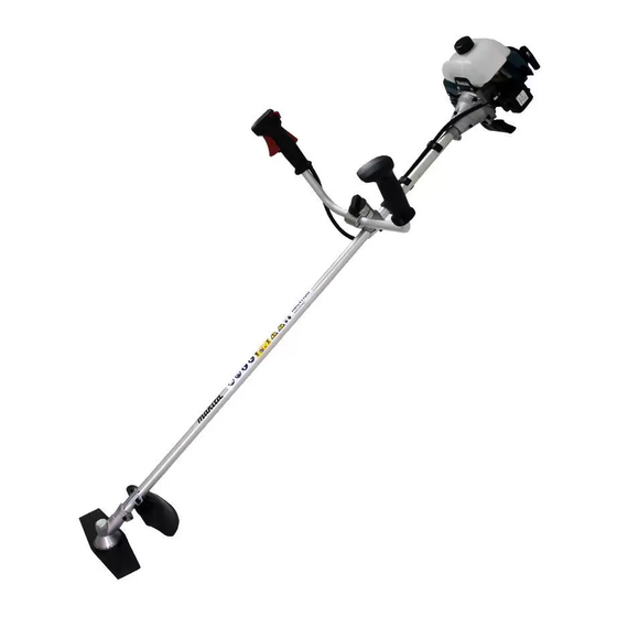
Page 8: Designation Of Parts
DESIGNATION OF PARTS RBC413U RBC414U DESIGNATION OF PARTS Fuel tank Clutch case Hanger I-O switch (on/off) Throttle lever Throttle wire Handle Handle holder Shaft Cutting tool guard (Protector) Gear case Spark plug Exhaust muffler Exhaust pipe Recoil starter Starter knob... -
Page 9: Assembly Of Engine And Shaft
Always wear protective gloves! CAUTION: Start the brushcutter only after having assembled it completely. For model RBC413U – Place the handle with the throttle lever on the handle holder on the right side (to be held by the right hand) and the other on the left side. -
Page 10: Mounting Of Protector
MOUNTING OF PROTECTOR To meet the applicable safety provisions, only the tool/protector combinations as indicated in the table must be used. Be sure to use genuine MAKITA cutter blades or nylon cutting head. – The cutter blade must be well polished, free of cracks or breakage. If the cutter blade hits against a stone during operation, stop the engine and check the blade immediately. - Page 11 – In use of the metal blade, fix the protector (3) to the clamp (2) with two bolts (1). NOTE: Tighten the right and left bolts evenly so that the gap between the clamp (2) and the protector (3) will be constant. Otherwise, the protector sometimes may not function as specified.
-
Page 12: Mounting Of Cutter Blade Or Nylon Cutting Head
MOUNTING OF CUTTER BLADE OR NYLON CUTTING HEAD Turn the machine upside down, and you can replace the cutter blade or nylon cutting head easily. – Insert the hex wrench through the hole in the gear case and rotate the receiver Hex wrench washer (4) until it is locked with the hex wrench. -
Page 13: Fuels/Refuelling
Otherwise reliable function of the brushcutter cannot be guaranteed. The correct mixture ratio: Mix 25 parts gasoline with 1 part MAKITA 2-stroke engine oil (see table on right). NOTE: For preparing the fuel-oil mixture first mix the entire oil quantity with... -
Page 14: Correct Handling Of Machine
CORRECT HANDLING OF MACHINE Either type I or II below is included in the tool package. Always wear the shoulder harness when operating the brushcutter. Type I Attachment of shoulder harness – Adjust the strap length so that the cutter blade will be kept parallel with the ground. -
Page 15: Putting Into Operation
PUTTING INTO OPERATION Observe the applicable accident prevention regulations! Starting Move at least 3m (10ft) away from the place of refuelling. Place the brushcutter on a clean piece of ground taking care that the cutting tool does not come into contact with the ground or any other objects. Cold start –... -
Page 16: Resharpening The Cutting Tool
Starting the warm engine – As described above, except without moving the choke lever (choke lever remains in the down position). Stopping 1) Release the throttle lever (2) fully, and when the engine rpm has lowered, set the I-O switch (1) to STOP the engine will now stop. 2) Be aware that the cutting head may not stop immediately and allow it to slow down fully. - Page 17 NYLON CUTTING HEAD Most effective cutting area The nylon cutting head is a dual line trimmer head that has bump & feed mechanism or auto feed mechanism (ultra auto) (country specific). The nylon cutting head with bump & feed mechanism feeds out the nylon cord after tapping the trimmer head on the ground.
- Page 18 Mount the spool in the housing so that the grooves and protrusions on the spool match up with those in the housing. Keep the side with letters on the spool visible on the top. Now, unhook the ends of the cord from their temporary position and feed Eyelets the cords through the eyelets to come out of the housing.
- Page 19 4. Wind the lines up firmly to the direction slown by left-hand (LH) arrow on the flange. Do not cross the lines. To “LH” direction Wind tightly 5. Wind all but about 100 mm (3-15/16”) of the cords, leaving the end temporarily hooked through a notch on the side of the spool.
-
Page 20: Maintenance Schedule
Gear case the grease hole (3) every 30 hours. (Genuine MAKITA grease may be purchased from your MAKITA dealer.) 6. Cleaning of muffler exhaust port: Every 50 hours (Monthly) If the exhaust port (4) is clogged with carbon, remove it by scraping and tapping gently with a screwdriver or the like. -
Page 21: Storage
General Engine assembly, screws and nuts Visual inspection for damage and tightness Check for general condition and security After each refuelling Throttle lever Functional check Safety lock key Functional check ON-OFF switch Functional check Daily Sponge element (air filter) To be cleaned Cooling air duct To be cleaned Cutting blade... -
Page 22: Troubleshooting
TROUBLESHOOTING Before making a request for repairs, check a trouble for yourself. If any abnormality is found, control your machine according to the description of this manual. Never tamper or dismount any part contrary to the description. For repairs, contact Authorized Service Agent or local dealership. State of abnormality Probable cause (malfunction) Remedy... - Page 24 Makita Corporation www.makita.com 885333-2...
Need help?
Do you have a question about the RBC413U and is the answer not in the manual?
Questions and answers