
Related Manuals for KSB AmaControl INT 600 DM


Summary of Contents for KSB AmaControl INT 600 DM
- Page 1 Protection Module for Water and Waste Water Products AmaControl INT 600 DM Gateway Supplementary Operating Manual...
- Page 2 All rights reserved. The contents provided herein must neither be distributed, copied, reproduced, edited or processed for any other purpose, nor otherwise transmitted, published or made available to a third party without the manufacturer's express written consent. Subject to technical modification without prior notice. © KSB SE & Co. KGaA, Frankenthal 2023-04-13...
-
Page 3: Table Of Contents
Contents Contents Supplementary Operating Manual ....................... 4 General................................ 4 INT 600 DM Gateway............................ 4 1.2.1 Functional description of the INT 600 DM Gateway................. 4 1.2.2 Application of INT 600 DM Gateway .................... 5 Configuration of INT 600 DM Gateway ...................... 6 1.3.1 Safety regulations .......................... 6 1.3.2 Setting Modbus start addresses for INT 600 DM Gateway ............... -
Page 4: Supplementary Operating Manual
1 Supplementary Operating Manual 1 Supplementary Operating Manual 1.1 General This supplementary operating manual accompanies the installation/operating manual. All information contained in the installation/operating manual must be observed. Table 1: Relevant operating manuals Type series Reference number of the installation/operating manual Amacontrol 2301.82 1.2 INT 600 DM Gateway... -
Page 5: Application Of Int 600 Dm Gateway
NOTE Short circuit ▷ Only KSB AmaControl devices may be connected to the DP interface. The diagnostic system can output data recorded by AmaControl via the DP interface. The operating status of the pump can thus be evaluated in the actual application. -
Page 6: Configuration Of Int 600 Dm Gateway
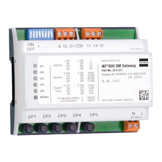
1 Supplementary Operating Manual 1.3 Configuration of INT 600 DM Gateway 1.3.1 Safety regulations DANGER Contact with live components Danger of death from electric shock! ▷ Any settings on the device shall only be performed when it has been disconnected from the power supply (de-energised). 1.3.2 Setting Modbus start addresses for INT 600 DM Gateway Fig. 1: The settings can be configured using DIP switches 1 and 2. -
Page 7: Setting The Baud Rate
1 Supplementary Operating Manual Example Each INT 600 DM Gateway DP input uses 3 Modbus addresses. The first device on DP1 #1, the second device on DP2 #4 etc. The INT 600 DM Gateway itself uses address #16 (start address +15). The 3 addresses are provided for additional AmaControl devices at a DP input. -
Page 8: Setting Stop Bits And Parity
1 Supplementary Operating Manual 1.3.4 Setting stop bits and parity Stop bits / parity Fig. 3: Setting stop bits and parity via DIP switches 5 and 6 Table 9: Selection of stop bits / parity DIP switch 5 DIP switch 6 Address 1 / even 1 / odd 2 / no (factory setting) -
Page 9: Modbus Termination
1 Supplementary Operating Manual 1.3.6 Modbus termination Termination Fig. 5: Setting terminating resistor for Modbus RTU via DIP switch 8 Table 11: Setting terminating resistor DIP switch 8 Address Activated Deactivated (factory setting) 1.3.7 Modbus start register The Modbus start registers of the different AmaControl devices when accessing Modbus INT 600 DM Gateway are as follows: Table 12: Modbus start register Designation... -
Page 10: Triggering Remote Reset
1 Supplementary Operating Manual 1.3.8 Triggering remote reset INT 600 DM Gateway provides a volt-free changeover contact for resetting fault messages. The relay is controlled via register dec 9735. Sequence of control commands with (FC10) (Preset Multiple Registers): write dec 15,300 once and then dec 42,455. - Page 11 1 Supplementary Operating Manual Start Description Data type 8223 8223 Mean value of frequency (all 3 phases) u 16bit 0 = not assigned 1 = frequency 0 Hz 2 = incorrect phase sequence 3…65535 motor supply frequency in Hz 8228 8228 Number of hours of the current day (internal time) u 8bit...
- Page 12 1 Supplementary Operating Manual Start Description Data type 8251 8251 Module condition, relay monitoring u 16bit High byte: error number Low byte: module condition, bit-coded Bit 0 = active Bit 1 = warning Bit 2 = fault Bit 3 = re-start delay Bit 4 = interlocked 8252 8252...
- Page 13 1 Supplementary Operating Manual Start Description Data type 8282 8282 Number of running times 30 - 59 min u 8bit Number to determine the quasi-percentage distribution 8283 8283 Number of running times 60 - 119 min u 8bit Number to determine the quasi-percentage distribution 8284 8284 Number of running times 120 - 300 min...
- Page 14 1 Supplementary Operating Manual Start Description Data type 8344 8344 Sum over lifetime: phase asymmetry detected u 16bit Alert The following event numbers are counted: {29} 8345 8345 Sum over lifetime: phase asymmetry detected u 16bit Alert, interlocked 8348 8348 Sum over lifetime: internal fault u 16bit Warning...
- Page 15 1 Supplementary Operating Manual Start Description Data type 8388 8388 Fault history: error number of the 10th error u 8bit 8389 8389 Fault history: time between the 10th error and the error before that u 8bit 0..120 = 0..120 min 121..238 = 3..120 h 8392 8392...
- Page 16 1 Supplementary Operating Manual Start Description Data type 8501 8501 Sum over lifetime: phase monitoring, overvoltage u 16bit Warning 8502 8502 Sum over lifetime: phase monitoring, undervoltage Alert u 16bit 8503 8503 Sum over lifetime: phase monitoring, undervoltage u 16bit Alert, interlocked 8504 8504...
- Page 17 1 Supplementary Operating Manual Start Description Data type 8560 8560 Module condition, current loop u 16bit High byte: error number Low byte: module condition, bit-coded Bit 0 = active Bit 1 = warning Bit 2 = fault Bit 3 = re-start delay Bit 4 = interlocked 8562 8562...
- Page 18 1 Supplementary Operating Manual Start Description Data type 8578 8578 Sum over lifetime: current loop, warning value exceeded u 16bit Warning The following error numbers are counted: {127} 8579 8579 Sum over lifetime: current loop, sensor fault u 16bit Alert The following error numbers are counted: {69} 8580 8580...
- Page 19 1 Supplementary Operating Manual Start Description Data type 8603 8603 Module condition, phase overvoltage u 16bit High byte: error number Low byte: module condition, bit-coded Bit 0 = active Bit 1 = warning Bit 2 = fault Bit 3 = re-start delay Bit 4 = interlocked 8604 8604...
-
Page 20: Modbus Protocol, Amacontrol 4 (Modbus Interface)
1 Supplementary Operating Manual 1.4.2 Modbus protocol, AmaControl 4 (Modbus interface) NOTE AmaControl 4 has an integrated Modbus RTU interface. Alternatively, AmaControl 4 can be read out using the INT 600 DM Gateway. Table 14: Modbus Protocol, AmaControl 4 Start Description Data type 8192 8192... - Page 21 1 Supplementary Operating Manual Start Description Data type 8228 8228 Number of hours of the current day (internal time) 0-23 h u 16bit 8232 8232 Module condition, motor temperature u 16bit High byte: error number Low byte: module condition, bit-coded Bit 0 = active Bit 1 = warning Bit 2 = fault Bit 3 = re-start delay...
- Page 22 1 Supplementary Operating Manual Start Description Data type 8245 8245 Motor current actual value u 16bit Current = value * 10 mA 0.01...655.35 A 8246 8246 Module condition, cos phi monitoring u 16bit High byte: error number Low byte: module condition, bit-coded Bit 0 = active Bit 1 = warning Bit 2 = fault...
- Page 23 1 Supplementary Operating Manual Start Description Data type 8253 8253 Module condition, phase overvoltage u 16bit High byte: error number Low byte: module condition, bit-coded Bit 0 = active Bit 1 = warning Bit 2 = fault Bit 3 = re-start delay Bit 4 = interlocked 8254 8254...
- Page 24 1 Supplementary Operating Manual Start Description Data type 8295 8295 Temperature sensor 2, actual value s 16offset Temperature = (value - 32768) / 100-327.00 °C…+327.00 °C 65535 = not available 8296 8296 Phase voltage L10...65535 V u 16bit 8297 8297 Phase voltage L20...65535 V u 16bit 8298 8298...
- Page 25 1 Supplementary Operating Manual Start Description Data type 8438 8438 Sum over lifetime: u 16bit temperature sensor 1, short circuit Tripping The following event numbers are counted: {58} 8439 8439 Sum over lifetime: u 16bit temperature sensor 1, open circuit Tripping The following event numbers are counted: {59} 8440...
- Page 26 1 Supplementary Operating Manual Start Description Data type 8454 8454 Sum over lifetime: u 16bit current transformer input 1, sensor fault Tripping The following error numbers are counted: {} 8455 8455 Sum over lifetime: u 16bit Current transformer input 1 Warnings The following error numbers are counted: {} 8456...
- Page 27 1 Supplementary Operating Manual Start Description Data type 8470 8470 Sum over lifetime: u 16bit frequency of starts limit Tripping The following error numbers are counted: {7} 8471 8471 Sum over lifetime: u 16bit frequency of starts limit Interlocked tripping The following error numbers are counted: {7} 8472 8472...
- Page 28 1 Supplementary Operating Manual Start Description Data type 8527 8527 Sum over lifetime: u 16bit motor detected as running even though the relay was switched off Message The following error numbers are counted: {11},{118},{246} 8554 8554 Sum over lifetime: u 16bit power reset Message The following event numbers are counted: {1}...
- Page 29 1 Supplementary Operating Manual Start Description Data type 8642 8642 Maximum of the switching cycles per hour of the previous day (current u 16bit day - 1 day; internal time) 0...255 8643 8643 Maximum of the switching cycles per hour of two days ago (current day - u 16bit 2 days;...
-
Page 30: Modbus Protocol, Amacontrol 4 (Dp Interface Int 600 Dm Gateway)
1 Supplementary Operating Manual 1.4.3 Modbus protocol, AmaControl 4 (DP interface INT 600 DM Gateway) Parameters can be read with function code 4 (read input register). NOTE AmaControl 4 has a separate Modbus RTU interface (ð Section 1.4.2, Page 20) . Alternatively, however, AmaControl 4 can also be read out using the INT 600 DM Gateway. - Page 31 1 Supplementary Operating Manual Start Data type Description 10789 10789 Running time until service due, in hours u 16bit 10794 10794 Module condition, temperature 1 u 16bit High byte: error number Low byte: module condition, bit-coded Bit 0 = active Bit 1 = warning Bit 2 = fault Bit 3 = re-start delay...
- Page 32 1 Supplementary Operating Manual Start Data type Description 10912 10912 Event memory: index, current event, position in rolling event memory u 16bit 0...65,535 10913 10913 Event memory: index, current measured value set Position in rolling u 16bit measured value memory 0...65,535 10914 10914 Event memory: last event, time stamp 0...4,294,967,295 Seconds elapsed...
- Page 33 1 Supplementary Operating Manual Start Data type Description 11005 11005 Sum over lifetime: u 16bit leakage monitoring 1 Interlocked tripping The following error numbers are counted: {64},{65} 11032 11032 Sum over lifetime: u 16bit device fault Tripping The following event numbers are counted: {31} 11033 11033 Sum over lifetime:...
- Page 34 1 Supplementary Operating Manual Start Data type Description 11176 11176 Number of running times 10 - 19 minutes u 16bit Number to determine the quasi-percentage distribution 11177 11177 Number of running times 20 - 29 minutes u 16bit Number to determine the quasi-percentage distribution 11180 11180 Number of running times 120 - 300 minutes...
-
Page 35: Modbus Protocol, Amacontrol L
1 Supplementary Operating Manual 1.4.4 Modbus protocol, AmaControl L NOTE The AmaControl L Modbus registers are read using the INT 600 DM Gateway. Table 16: Modbus protocol, AmaControl L Start Description Data type 10752 10752 High byte: visual ID u 16bit Low byte: reserved 10753 10753... - Page 36 1 Supplementary Operating Manual Start Description Data type 10789 10789 Running time until service due, in hours u 16bit 10792 10792 Module condition, motor temperature u 16bit High byte: error number Low byte: module condition, bit-coded Bit 0 = active Bit 1 = warning Bit 2 = fault Bit 3 = re-start delay...
- Page 37 1 Supplementary Operating Manual Start Description Data type 10913 10913 Event memory: index, current measured values set u 16bit Position in rolling measured value memory 0...65 535 10914 10915 Event memory: last event, time stamp u 32bit 0...4,294,967,295 seconds elapsed since 01/01/1970 00:00:00, POSIX format 10916 10916...
- Page 38 1 Supplementary Operating Manual Start Description Data type 11076 11076 Sum over lifetime: u 16bit temperature sensor 1 Warning The following event numbers are counted: {123} 11114 11114 Sum over lifetime: u 16bit power reset Message The following event numbers are counted: {1} 11115 11115 Sum over lifetime:...
- Page 39 1 Supplementary Operating Manual Start Description Data type 11203 11203 Maximum of the switching cycles per hour of two days ago (current day - u 16bit 2 days; internal time) 0...255 11204 11204 Maximum of the switching cycles per hour of three days ago (current u 16bit day- 3 days;...
-
Page 40: Overview Of The Most Important Registers
1 Supplementary Operating Manual 1.4.5 Overview of the most important registers Table 17: List of registers Description AmaControl 3 AmaControl 4 AmaControl L Via INT 600 DM Direct Via INT 600 DM Via INT 600 DM Internal seconds counter per 8216 8216 10776 10776 hour General fault 8198... - Page 41 1 Supplementary Operating Manual Description AmaControl 3 AmaControl 4 AmaControl L Via INT 600 DM Direct Via INT 600 DM Via INT 600 DM Module condition, phase 8602 8252 10812 ✘ undervoltage Module condition, phase 8603 8253 10813 ✘ overvoltage Module condition, relay 8251 8254 10814...
-
Page 42: Modbus Error List
1 Supplementary Operating Manual 1.4.6 Modbus error list Table 18: Modbus error list Error text Type Description No error Message No error Motor temperature, shutdown Error The permissible motor temperature has been exceeded. Resistance value PTC > trigger value (standard 4.5 kΩ) Motor temperature, rise too fast Error Excessively fast temperature rise in the motor winding. - Page 43 1 Supplementary Operating Manual Error text Type Description Analog input 1, shutdown Error Permissible current value at the analog input has been exceeded or undershot. If the error occurs directly after start-up, check "Time to monitoring" if necessary. Analog input 1, sensor error Error Permissible closed-circuit current has been undershot.
-
Page 44: Related Documents
1 Supplementary Operating Manual Error text Type Description Frequency inverter Warning Excessive percentage deviation of one phase from the mean value of the 3 phases (asymmetry). Temperature 3 Warning Permissible warning value for the temperature at the temperature input has been exceeded. Temperature 3, warning Warning Temperature 3, warning... - Page 45 1 Supplementary Operating Manual Feature Characteristic Value Activation of remote Quantity Max. 3 activations within 1 day reset Relay Contact AC 240 V 2.5 A C300 at least AC/ DC 24 V 20 mA Mechanical service life Approx. 1 million switching cycles Modbus Protocol Modbus RTU (2-wire interface/ W2-Modbus) Start addresses Adjustable 1...
-
Page 46: Wiring Diagram Of Int 600 Dm Gateway
1 Supplementary Operating Manual 1.5.1.1 Wiring diagram of INT 600 DM Gateway Fig. 6: Wiring diagram of INT 600 DM Gateway 1.5.1.2 Outline drawing of INT 600 DM Gateway Fig. 7: Outline drawing of INT 600 DM Gateway AmaControl 46 of 48... - Page 48 KSB SE & Co. KGaA Johann-Klein-Straße 9 • 67227 Frankenthal (Germany) Tel. +49 6233 86-0 www.ksb.com...
Need help?
Do you have a question about the AmaControl INT 600 DM and is the answer not in the manual?
Questions and answers