Soundoff Signal 400 Series Manual
8 button controller w/ slide switch kit
Hide thumbs
Also See for 400 Series:
- Quick start manual (10 pages) ,
- Installation instructions manual (19 pages)
Advertisement
-
ETCPRSP01
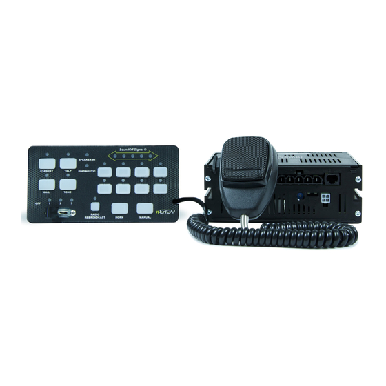
8 BUTTON CONTROLLER W/ SLIDE SWITCH - KIT
PSRN4ANRI - 100W
Package Contents:
1 ea. Amplifier Box
1 ea. Microphone Bracket w/ Mounting
Hardware
5 ea. Amplifier Wire Harnesses with
Connectors (1-4 pin, 1-12 pin, 1-5
pin 1-14 pin and 1-8 pin)
2 ea. Instruction Manual
1 ea. Operators Warning Card to remain
in vehicle for operator review
1 ea. Sound Pressure Warning Label that
is to be attached in vehicle and in
plain site of operator and occupants
of the vehicle
1 ea. Mounting Bracket with Hardware
1 ea. Label Card for Aux. Switches
1 ea. Remote control panel
Please see page 3 for
Technical Specifications
1.800.338.7337 / www.soundoffsignal.com
Pg. 1
Amplifier
5
4
E
D
PCPRSP01
C
B
A
5
4
WARNING
!
Sirens produce loud sounds that
may damage hearing:
- Roll up windows.
- Wear hearing protection.
- Use only for emergency response.
- Avoid exposure to siren sound
outside of vehicle.
Microphone
3
2
1
E
D
C
8 Button Control Panel
PROPRIETARY AND CONFIDENTIAL
THE INFORMATION CONTAINED IN
B
THIS DRAWING IS THE SOLE
PROPERTY OF SOUNDOFF SIGNAL.
ANY REPRODUCTION IN PART OR
®
AS A WHOLE WITHOUT THE
TOLERANCES
WRITTEN PERMISSION OF
SOUNDOFF SIGNAL IS PROHIBITED.
EXCEPT AS NOTED
.X
± .020
THIRD ANGLE
CAD DIMENSIONS ARE BASIC
.XX
± .012
.XXX ± .006
PROJECTION
UNLESS OTHERWISE SPECIFIED
ANGLES ± .5°
A
DRAWING
PRIMARY DIMS: INCH
SIZE:
GD&T TO FOLLOW
DUAL DIMS: [mm]
ASME Y14.5M-2009
DO NOT SCALE
MATERIAL:
DESCRIPTION:
A
DRAWING NO:
REVISION:
D1_Remote Console Panel Assy
SHEET
1 OF 1
3
2
1
Introduction
The ETCPRSP01 is Remote Mounted
Controller and amplifier with lighting control.
It can drive a variety of programmable
powered control lines capable of up to nine
10A and three 20A circuits.
Notice
Controllers provide an essential function of
an effective visual warning system.
However, this controller is only a short range
secondary device. The use of this controller
does not insure that all drivers can or will
abide by or react to an emergency warning
signal, especially at high rates of speeds or
long distances. The operator of the vehicle
must never take the right of way for granted
and it is the operator's responsibility to
proceed safely.
The effectiveness of this system is highly
dependant on the correct mounting and
wiring. The installer must read and follow
the manufacturer's installation instructions
and warnings in the manual. The vehicle
operator should verify the system is securely
fastened to the vehicle and properly
functioning.
This system is intended for use by
authorized personnel only. It is the user's
responsibility to ensure they understand and
operate the emergency warning devices in
compliance with all applicable city, state,
and federal laws and regulations. SoundOff
Signal assumes no liability for any loss
resulting from the use of this system.
IMPORTANT NOTICE TO INSTALLER:
Make sure to read and understand all
instructions and warnings before proceeding
with the installation of this product. Ensure
the manual and all warning cards are
delivered to the end user of this equipment.
ETCPRSP01 0718
Advertisement
Table of Contents

Related Manuals for Soundoff Signal 400 Series


Summary of Contents for Soundoff Signal 400 Series
- Page 1 8 Button Control Panel 1 ea. Remote control panel PROPRIETARY AND CONFIDENTIAL THE INFORMATION CONTAINED IN THIS DRAWING IS THE SOLE PROPERTY OF SOUNDOFF SIGNAL. ANY REPRODUCTION IN PART OR ® AS A WHOLE WITHOUT THE TOLERANCES WRITTEN PERMISSION OF SOUNDOFF SIGNAL IS PROHIBITED.
-
Page 2: Replacement Parts And Accessories
Fuse Kit PSRN4HDK1 Harness Kit PROPRIETARY AND CONFIDENTIAL THE INFORMATION CONTAINED IN THIS DRAWING IS THE SOLE PSRN4MTBK1 Mounting Bracket PROPERTY OF SOUNDOFF SIGNAL. ANY REPRODUCTION IN PART OR ® AS A WHOLE WITHOUT THE TOLERANCES WRITTEN PERMISSION OF PSRNLEG1... - Page 3 400 SERIES AMPLIFIER BOX TECHNICAL SPECIFICATIONS Overall Dimensions: MOUNTING PSRN4ANR1 Control Panel: 3.51” W x 6.89”H x 1.17”D -Amplifier Installation- Amplifier/Relay: 2.62”H x 7.00”W x 6.51”D Before drilling holes, check for clearance to prevent Input Voltage: 10 - 16Vdc (negative ground) damage.
-
Page 4: Audio Wiring
400 SERIES AMPLIFIER BOX Auxiliary Input: (Violet Wire) Park Kill Input: (Yellow Wire) The input is an optional input which will remotely activate the The input will silence the tones when the input wire PSRN4ANR1 unit when the auxiliary input wire is connected to ground. If this is activated. -
Page 5: Fuse Chart
400 SERIES AMPLIFIER BOX Internal Relay Board Fuse replacement: PSRN4ANR1 To replace fuses: RED/ BLACK Auxiliary Push-Button 7 Normally Open Output Remove power connectors CN8 and CN6 or remove power GREEN/ BLACK Auxiliary Push-Button 8 Normally Open Output to unit. -
Page 6: Remote Control Panel
PROPRIETARY AND CONFIDENTIAL Sirens produce loud sounds that THE INFORMATION CONTAINED IN may damage hearing: THIS DRAWING IS THE SOLE PROPERTY OF SOUNDOFF SIGNAL. - Roll up windows. ANY REPRODUCTION IN PART OR ® AS A WHOLE WITHOUT THE WRITTEN PERMISSION OF - Wear hearing protection. -
Page 7: Programming Modes
REMOTE CONTROL PANEL ETCPRSP01 - 8 Button Controller w/ Radio Rebroadcast and Slide Switch PROGRAMMING MODES AUXILIARY SWITCH SETTINGS: SLIDE SWITCH SETTINGS: Refer to Siren Amplifier Diagnostic Indicator Chart below for Button and LED locations and 1. Press and hold Auxiliary Push-Button “1” and “4” until slide switch #2 indicator LED flashes. terminology 2. -
Page 8: Alternate Modes
REMOTE CONTROL PANEL ETCPRSP01 - 8 Button Controller w/ Radio Rebroadcast and Slide Switch ALTERNATE MODES: SLIDE SWITCH MAPPING PROGRAMMING: Press and Hold Auxiliary Button “2” and “6” until Slide Switch indicator #1 and indicator #2 LED flashes. Allows the operator to have the siren automatically turn on auxiliary push-buttons based on the position of the slide switch. - Page 9 Improper use or installation may void warranty coverage. To review our Limited Warranty Statement & Return Policy for this or any SoundOff Signal product, visit our website at www.soundoffsignal.com/tech-services/returns/. If you have questions regarding this product, contact Technical Services, Monday - Friday, 8 a.m. to 5 p.m. or after hours 5 p.m. to 8 p.m. ET at 1.800.338.7337 (press #4).
Need help?
Do you have a question about the 400 Series and is the answer not in the manual?
Questions and answers