Advertisement
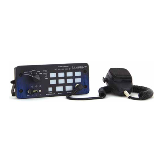
400 SERIES CONSOLE SIREN
ROTARY OR PUSH-BUTTON
USER INTERFACE
ENGSCP7141 - 10OW
ENGSCP7152 - 200W
ENGSCR7141 - 100W
ENGSCR7152 - 200W
PUSH BUTTON
ENGSCP7141 - 10OW
ENGSCP7152 - 200W
WARNING
Please see page 3 for Technical Specifications
•HIGH CURRENT interconnects must be properly terminated. Poor crimp quality can cause heat
build-up and fire. Follow crimp connector manufacturer instructions.
•DO NOT install this product or route any wires in the Air Bag Deployment Zone. Refer to vehicle
Owner's Manual for deployment zones.
•Do NOT use system to disconnect headlights, brake lights or other safety equipment.
•Unit may become hot to touch during normal operation.
•Failure to properly install connectors, fuses or wiring may cause vehicle failure or fire.
•Installation must only be performed by trained technician. Installer must determine vehicle wiring
configuration and proper integration of system.
•Use proper wire gauge. All power wires connecting to positive (+) or negative (-) battery terminal
or local chassis ground (-) must be sized to supply at least 125% of max. current and properly fused at
power source.
•Install protective grommets when routing wire through firewall or metal.
1.800.338.7337 / www.soundoffsignal.com
Pg. 1
ROTARY
ENGSCR7141 - 100W
ENGSCR7152 - 200W
Installers and users must comply with all applicable federal, state and local laws regarding use and installation of warning devices.
To review our Limited Warranty Statement & Return Policy for this or any SoundOff Signal product, visit our website at www.soundoffsignal.com/tech-services/returns/.
If you have questions regarding this product, contact Technical Services, Monday - Friday, 8 a.m. to 5 p.m. or after hours 5 p.m. to 8 p.m. ET at 1.800.338.7337 (press #4).
Questions or comments that do not require immediate attention may be emailed to techservices@soundoffsignal.com.
S U P E R I O R C U S TO M E R R E L AT I O N S H I P S . S M A RT LY D E S I G N E D L I G H T I N G & E L E C T R O N I C S O L U T I O N S .
WARNING
!
Sirens produce loud sounds that
may damage hearing:
- Roll up windows.
- Wear hearing protection.
- Use only for emergency response.
- Avoid exposure to siren sound
outside of vehicle.
Package Contents:
1 ea. Console Siren
4 ea. Amplifier Wire Harnesses with
Connectors (1-4 pin, 1-12 pin, 1-5
pin and 1-14 pin)
1 ea. Instruction Manual
1 ea. Operators Warning Card to remain
in vehicle for operator review
1 ea. Sound Pressure Warning Label that
is to be attached in vehicle and in
plain site of operator and occupants
of the vehicle
1 ea. Mounting Bracket with Hardware
1 ea. Label Card for Aux. Switches
IMPORTANT NOTICE TO INSTALLER:
Make sure to read and understand all
instructions and warnings before proceeding
with the installation of this product. Ensure the
manual and all warning cards are delivered to
the end user of this equipment.
NOTICE:
Improper use or installation may void warranty coverage.
Introduction
The ETSA48(1,2)CS(R,P) is a console
(DASH) mounted all in one siren and light
controller. It comes in 4 styles differing in
the user interface method and the amount of
speaker power available. This siren can also
drive a variety of programmable powered
control lines capable of up to nine 10A and
three 20A circuits.
Notice
Sirens provide an essential function of an
effective audio / visual warning system.
However, sirens are only short range
secondary devices. The use of a siren does
not insure that all drivers can or will abide
by or react to an emergency warning signal,
especially at high rates of speeds or long
distances. The operator of the vehicle must
never take the right of way for granted and
it is the operator's responsibility to proceed
safely.
The effectiveness of this siren system is
highly dependant on the correct mounting
and wiring. The installer must read and
follow the manufacturer's installation
instructions and warnings in the manual.
The vehicle operator should verify the siren
system is securely fastened to the vehicle
and properly functioning.
Effective sirens generate loud sound
pressure levels that can potentially cause
hearing damage. Installers and those around
the vehicle need to be aware of the dangers
and wear hearing protection whenever the
siren system is operating. Vehicle operators
and occupants should assess their exposure
to siren noise and determine what steps
need to be taken to prevent hearing damage.
The siren system is intended for use by
authorized personnel only. It is the user's
responsibility to ensure they understand and
operate the emergency warning devices in
compliance with all applicable city, state,
and federal laws and regulations. SoundOff
Signal assumes no liability for any loss
resulting from the use of the siren system.
ENGSC(x)(xxxx) 0419
Advertisement
Table of Contents

Related Manuals for Soundoff Signal ENGSCP7141


Summary of Contents for Soundoff Signal ENGSCP7141
- Page 1 Improper use or installation may void warranty coverage. To review our Limited Warranty Statement & Return Policy for this or any SoundOff Signal product, visit our website at www.soundoffsignal.com/tech-services/returns/. If you have questions regarding this product, contact Technical Services, Monday - Friday, 8 a.m. to 5 p.m. or after hours 5 p.m. to 8 p.m. ET at 1.800.338.7337 (press #4).
-
Page 2: Replacement Parts And Accessories
400 SERIES CONSOLE SIREN ROTARY OR PUSH-BUTTON USER INTERFACE ENGSCP7141 - 10OW ENGSCP7152 - 200W ENGSCR7141 - 100W ENGSCR7152 - 200W REPLACEMENT PARTS & ACCESSORIES Replacement Parts & Accessories: PSRN4ANR1 Replacement Amp/Relay Assembly-100 Watt PSRN4ANR2 Replacement Amp/Relay Assembly-200 Watt PSRN4HDK2... -
Page 3: Technical Specifications
TECHNICAL SPECIFICATIONS 400 SERIES AMPLIFIER BOX MOUNTING Overall Dimensions: PSRN4ANR1 -Siren Installation- Control Panel: 3.51” W x 6.89”H x 1.17”D PSRN4ANR2 Amplifier/Relay: 2.62”H x 7.00”W x 6.51”D Siren must be mounted using fasteners in the side t-slots. Before drilling holes, check for clearance to Input Voltage: 10 - 16Vdc (negative ground) prevent damage. - Page 4 Park Kill Input: (Yellow Wire) Auxiliary Input: (Violet Wire) The input will silence the siren tone when the input The input is an optional input which will remotely 400 SERIES AMPLIFIER BOX wire is activated. The input is typically connected activate the siren when the auxiliary input wire is con- to the transmission neutral safety switch.
- Page 5 400 SERIES AMPLIFIER BOX Internal Relay Board Fuse replacement: PSRN4ANR1 To replace fuses: RED/ BLACK Auxiliary Push-Button 7 Normally Open Output PSRN4ANR2 Remove power connectors CN8 and CN6 or remove power GREEN/ BLACK Auxiliary Push-Button 8 Normally Open Output to unit. RED/ WHITE Auxiliary Push-Button 7 Normally Closed Output Remove unit from console or obtain access to full top of unit.
-
Page 6: Control Panel
CONTROL PANEL PNGCP18003 Horn Ring Configuration Settings *Siren Tone Must Be ON* PNGCP18004 PROGRAMMING MANUAL Hornring Latch Hornring Hornring (see #4 in OTHER Output Behavior Scroll Timeout PUSH BUTTON (SHOWN BELOW) SIMILAR TO ROTARY SWITCH MODES on pg. 7.) 4. Level 3 tone activation*: Determines when the siren tone Pressing the horn in this mode (NOT SHOWN) push-buttons on control panel are enabled. -
Page 7: Alternate Modes
CONTROL PANEL 7. Slide Switch Enabled Without Ignition: After ignition ALTERNATE MODES: is turned off, device will stay on in lower power mode and allow PNGCP18003 (ONLY) the slider to operate. 1. Press and Hold Auxiliary Push-Button “2” and “6” until Slide PNGCP18004 Switch indicator #1 and #2 LED flashes. - Page 8 CONTROL PANEL PROGRAMMING MODES Slide switch mapping programming: Allows the operator to have the siren automatically turn on auxiliary PNGCP18003 push-buttons or tones based on the position of the slide switch. AUXILIARY SWITCH SETTINGS: PNGCP18004 Refer to Siren Amplifier Diagnostic Indicator Chart below for Button and LED If an auxiliary or tone push-button is programmed to turn ON when PROGRAMMING MANUAL locations and terminology...
- Page 9 CONTROL PANEL PNGCP18003 PNGCP18004 PROGRAMMING MANUAL PARK KILL SETTINGS: Enables auxiliary and slider outputs to be disabled when Park Kill input is active. Auxiliary outputs can be turned back on by pushing the buttons again; slider outputs are disabled as long as the Park Kill input is active. 1.
-
Page 10: Horn Button
CONTROL PANEL PNGCP18003 PNGCP18004 PROGRAMMING MANUAL WAIL BUTTON TONE BUTTON HORN BUTTON BUTTON BUTTON BUTTON SPKR A SPKR B BUTTON BUTTON BUTTON BUTTON SPKR A SPKR B BUTTON BUTTON BUTTON BUTTON BUTTON SPKR A SPKR B WAIL 1 WAIL 1 HORN 1 HORN 1 TONE...
Need help?
Do you have a question about the ENGSCP7141 and is the answer not in the manual?
Questions and answers