Table of Contents
Advertisement
Quick Links
Advertisement
Table of Contents

Related Manuals for Soundoff Signal EA-8


Summary of Contents for Soundoff Signal EA-8
- Page 1 INSTALLATION INSTRUCTIONS EA-8 CONTROLLER EA-8 Controller 0000KP 0724 REV A...
-
Page 2: Warning
• Improper use or installation may void warranty coverage. • To review our Limited Warranty Statement & Return Policy for this or any SoundOff Signal product, visit our website at https://soundoffsignal.com/warranty. • If you have questions regarding this product, contact Technical Services, Monday - Friday, 8 a.m. to 5 p.m. -
Page 3: Table Of Contents
Button Combo: Group 3 ........20 EA-8 Duplicator Operation Instructions ......20-21 Warranty &... -
Page 4: Contents
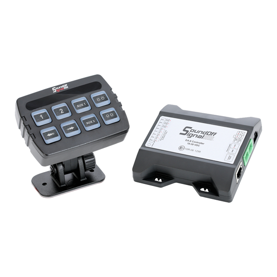
EA-8 CONTROLLER CONTENTS COMPONENT QTY. POWER MODULE CONTROLLER RJ45 CABLE (4M) TERMINAL BLOCK SELF-DRILLING SCREW (#8x1") 6-PIN WIRE HARNESS ADJUSTABLE SCREW MOUNT BRACKET SELF-DRILLING SCREW (4X15MM) DECALS INSTRUCTION CARD TECHNICAL SPECIFICATIONS Control Panel 68.8mm H x 96.9mm W x 25.5mm D... -
Page 5: Mounting
EA-8 CONTROLLER MOUNTING Screw Mount Bracket 2.72" (69.2mm) 2-R4.5 1.97" (50mm) 1. Choose a desired place for installation. 2. Use the base as the template to locate and mark two mounting holes on the mounting surface. 3. Secure the bracket with the two Ø4 self-drilling screws supplied. -
Page 6: Wiring
B1: If total load current from output 1 exceeds 15A, B1 will turn OFF, Green LED on B1 & 10 Amber TA LEDs will single flash and Beeper will sound together to show Overload or Short Circuit status. The EA-8 Controller will be locked out and must be RESET to use. -
Page 7: Programming & Operation
2. Press and hold B3 and B4 for more than 5 seconds. 3. If EA-8 Controller has been restored to factory default configuration successfully, the controller will return to operation mode (after “beep” for three times and green backlight is ON). -
Page 8: Standby Mode
It will turn off all button functions. (Refer to Programming Mode 2, page 17, for detailed information of Standby Mode Configuration) NOTE: After entering Standby Mode, Programming Mode CANNOT be accessed by default. If you want to enter Programming Mode, disconnect all power and reboot your EA-8 Controller. Standby By default, red backlight will flash to indicate under Standby Mode. -
Page 9: Scene 1 And Scene 2 Controlled By B5 And B6
EA-8 CONTROLLER B4 = POSITIVE OUTPUT 4 & NEGATIVE OUTPUT 2 ON/OFF Switch • Activate Positive Output 4 and Negative Output 2. B5 = POSITIVE OUTPUT 5 ON/OFF Switch • Activate Positive Output 5. B6 = POSITIVE OUTPUT 6 ON/OFF Switch •... -
Page 10: Programming Mode 1
EA-8 CONTROLLER PROGRAMMING MODE 1 (FOR SETTING B1 ~ B8 BUTTON FUNCTION) Setting Example: Programming Mode 1 • Press B1 and B3 for more than 1 second to enter Programming Mode 1. • Press B1 once, Setting #2 is currently selected. Press B1 again to go to Setting #3. - Page 11 EA-8 CONTROLLER B1 Setting (B1 controls Positive Output 1) • You can use B1 button as an ON/OFF switch that activates the main warning light. B1 may be interlocked by B2 (refer to B2 Setting, page 12). • When B1 (main warning light) is interlocked by B2 (siren), it is possible to activate B1 by pressing B2.
- Page 12 EA-8 CONTROLLER B2 Setting (B2 controls Positive Output 2 and Negative Output 1) • You can use B2 button as an ON/OFF switch that activates the siren. And B2 may interlock B1, when B1 (main warning light) is interlocked by B2 (siren), it is possible to activate B1 by pressing B2.
-
Page 13: Indicator Light
EA-8 CONTROLLER B3 Setting (B3 controls Positive Output 3) • You can use B3 button as an ON/OFF switch that activates grill warning light and it can be activated simultaneously when B1 (main warning light) is activated. Enter Programming Mode 1 and configure B3 Setting as the following table:... - Page 14 EA-8 CONTROLLER B4 Setting (B4 controls Positive Output 4 and Negative Output 2) • You can use B4 button as a switch that activates auxiliary devices or rear warning lights. Enter Programming Mode 1 and configure B4 Setting as the following table:...
- Page 15 EA-8 CONTROLLER B6 Setting (B6 controls Positive Output 6) • You can use B6 button as an ON/OFF switch that activates the traffic arrow function (left-arrow mode). B6 may be set as the start button of Scene 2 to activate all connected warning lights simultaneously. You can also include B6 into Group 1 / Group 2 / Group 3 to activate traffic arrow function mutually exclusive.
-
Page 16: Programming Mode 2
EA-8 CONTROLLER B8 Setting (B8 controls Positive Output 8) • You can use B8 button as an ON/OFF switch that activates the traffic arrow function (right-arrow mode). You can also include B8 into Group 1 / Group 2 / Group 3 to activate traffic arrow function mutually exclusive. - Page 17 EA-8 CONTROLLER • After finishing setting, press B2 and B4 for more than 1 second to exit and save your configuration. Standby Mode Setting, B1 • Under Programming Mode 2, you can change the entry conditions of Standby Mode by B1 Setting.
- Page 18 EA-8 CONTROLLER Buzzer Setting, B3 • Under Programming Mode 2, you can change the buzzer configuration by B3 Setting. Enter Programming Mode 2 and configure Buzzer Setting as the following table: INDICATOR LIGHT DESCRIPTION Set Buzzer to ON mmmmmmmm Default...
- Page 19 EA-8 CONTROLLER Traffic Arrow Indicator Setting, B6 • Under Programming Mode 2, you can change the configuration of Traffic Arrow Indicator by B6 Setting. NOTE: Setting #2~#4 are available only when B5, B6, B7, B8 are set as Group1 or Group2.
-
Page 20: Button Combo: Group 1
EA-8 CONTROLLER • If EA-8 Controller has been restored to factory default configuration successfully, the controller will return to operation mode (after “beep” for three times and green backlight is ON). Button Combo: Group 1 • If the B5, B6, B7, B8 are configured in the Group 1, they are mutually exclusive and only one button can be activated at the same time. -
Page 21: Duplicator Operation Instructions
(moving Right to Left) and B4 will turn Red while pasting the configuration. Once complete there are 2 beeps and, B4 LED will return to GRN. Note, it is expected that the EA-8 system will have the same installation wiring as the one being copied from. -
Page 22: Warranty & Goods Procedure
Each RMA # is good for only one (1) return and will expire (30) days after the date it was issued. Products must be shipped back to SoundOff Signal and the RMA # clearly marked on the outside of the package near the shipping label. Please use the...
Need help?
Do you have a question about the EA-8 and is the answer not in the manual?
Questions and answers