Airwell AWSI-CFV007-N11 Service Manual
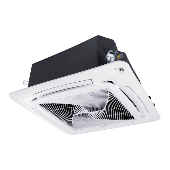
Round way cassette type indoor unit
Hide thumbs
Also See for AWSI-CFV007-N11:
- Operation & installation manual (24 pages) ,
- Service manual (194 pages)
Table of Contents
Advertisement
Advertisement
Table of Contents

Related Manuals for Airwell AWSI-CFV007-N11


Summary of Contents for Airwell AWSI-CFV007-N11
- Page 1 Round Way Cassette Type Indoor Unit Service Manual...
-
Page 2: Table Of Contents
CONTENTS 1. Features ......................1 2. Specification ......................2 3. Dimension......................10 4. Piping diagram....................11 5. Wiring diagram ....................12 6. Electric characteristics ..................13 7. Air velocity and temperature distribution............14 8. Sound pressure level ..................15 9. Installation ......................16 10. Dip Switch Setting ...................34 11. Indoor Unit Control ...................37 12. -
Page 3: Features
1. Features Name Code 7SP04H025 AWSI-CFV007-N11 7SP04H033 AWSI-CFV009-N11 AWSI-CFV012-N11 7SP04H026 7SP04H027 AWSI-CFV016-N11 7SP04H028 AWSI-CFV018-N11 AWSI-CFV024-N11 7SP04H029 7SP04H030 AWSI-CFV030-N11 AWSI-CFV038-N11 7SP04H031 7SP04H032 AWSI-CFV048-N11 7SP04H010 AWSI-CFV060-N11 ■ Unique round-way air outlet, no blind spot ■ Innovative 4 independent air flow control ■... -
Page 4: Specification
2. Specification Model AWSI-CFV007-N11 AWSI-CFV009-N11 AWSI-CFV012-N11 Power supply V-Ph-Hz 1/220~230/50/60 1/220~230/50/60 1/220~230/50/60 Capacity kBtu/h 12.3 Capacity Cooling Power input Current 0.15 0.15 0.15 Capacity kBtu/h 10.9 13.6 Capacity Power input Heating Current 0.15 0.15 0.15 Heating capacity at low temp. - Page 5 Model AWSI-CFV007-N11 AWSI-CFV009-N11 AWSI-CFV012-N11 Cabinet coating Galvanized Galvanized Galvanized type Cabinet salt spray Cabinet Hour test duration Control box IP class IP40 IP40 IP40 Sheet metal thickness Drain pan material Construction Drain pan insulation Drain pump option Standard 1200mm Standard 1200mm...
- Page 6 Model AWSI-CFV016-N11 AWSI-CFV018-N11 AWSI-CFV024-N11 Power supply V-Ph-Hz 1/220~230/50/60 1/220~230/50/60 1/220~230/50/60 Capacity kBtu/h 15.3 19.1 24.2 Capacity Cooling Power input Current 0.15 0.15 0.25 Capacity kBtu/h 17.1 21.5 27.3 Capacity Power input Heating Current 0.15 0.15 0.25 Heating capacity at low temp. Operating current 0.15 0.15...
- Page 7 Model AWSI-CFV016-N11 AWSI-CFV018-N11 AWSI-CFV024-N11 Cabinet coating Galvanized Galvanized Galvanized type Cabinet salt spray Cabinet Hour test duration Control box IP class IP40 IP40 IP40 Sheet metal thickness Drain pan material Construction Drain pan insulation Drain pump option Standard 1200mm Standard 1200mm Standard 1200mm Branch outlet option Material...
- Page 8 Model AWSI-CFV030-N11 AWSI-CFV038-N11 Power supply V-Ph-Hz 1/220~230/50/60 1/220~230/50/60 Capacity kBtu/h 30.7 38.2 Capacity 11.2 Cooling Power input Current 0.45 0.45 Capacity kBtu/h 34.1 42.6 Capacity 12.5 Power input Heating Current 0.45 0.45 Heating capacity at low temp. Operating current 0.45 0.45 Brand Broad ocean...
- Page 9 Model AWSI-CFV030-N11 AWSI-CFV038-N11 Cabinet coating Galvanized Galvanized type Cabinet salt spray Cabinet Hour test duration Control box IP class IP40 IP40 Sheet metal thickness Drain pan material Construction Drain pan insulation Drain pump option Standard 1200mm Standard 1200mm Branch outlet option Material Hot zinc plate Hot zinc plate...
- Page 10 Model AWSI-CFV048-N11 AWSI-CFV060-N11 Power supply V-Ph-Hz 1/220~230/50/60 1/220~230/50/60 Capacity kBtu/h 47.7 54.6 Capacity Cooling Power input Current 0.55 0.55 Capacity kBtu/h 54.6 61.2 Capacity Power input Heating Current 0.55 0.55 Heating capacity at low temp. Operating current 0.55 0.55 Brand Broad ocean Broad ocean Model...
- Page 11 Model AWSI-CFV048-N11 AWSI-CFV060-N11 Cabinet coating Galvanized Galvanized type Cabinet salt spray Cabinet Hour test duration Control box IP class IP40 IP40 Sheet metal thickness Drain pan material Construction Drain pan insulation Drain pump option standard 1200mm standard 1200mm Branch outlet option Material Hot zinc plate Hot zinc plate...
-
Page 12: Dimension
3. Dimension... -
Page 13: Piping Diagram
4. Piping diagram... -
Page 14: Wiring Diagram
5. Wiring diagram... -
Page 15: Electric Characteristics
6. Electric characteristics Units Power supply Indoor fan motor Power input (w) Volt. Output Model Phase Voltage Cooling Heating range AWSI- 50/60 198~242 0.39 1.24 0.31 CFV007-N11 AWSI- 50/60 198~242 0.39 1.24 0.31 CFV009-N11 AWSI- 50/60 198~242 0.39 1.24 0.31 CFV012-N11 AWSI- 50/60... -
Page 16: Air Velocity And Temperature Distribution
7. Air velocity distribution Air flow (m CFV007-018 CFV024 CFV030~038 CFV048~060 1. Strong speed 2. High speed 3. Medium speed 4. Low speed 5. Quiet... -
Page 17: Sound Pressure Level
8. Sound pressure level 1) Testing condition: a: Unit running in the normal condition b: Test in the semi-anechoic chamber c: Noise level varies from the actual factors such as room structure, etc. AWSI-CFV024-N11 AWSI-CFV007~018-N11 Limit of Limit of audible audible continuous continuous... -
Page 18: Installation
9. Installation 9.1 Installation procedures ■ If the air conditioner is transferred to a new user, this manual shall be transferred to the user, together with the conditioner. ■ Before installation, be sure to read Safety Considerations in this manual for proper installation. ■... - Page 19 ■ This appliance can be used by children aged from 8 years and above and persons with reduced physical, sensory or mental capabilities or lack of experience and knowledge if they have been given supervision or instruction concerning use of the appliance in a safe way and understand the hazards involved. Children shall not play with the appliance.
- Page 20 9.2 Maintenance ATTENTION ■ Repair can only be performed by professional personnel. ■ Before touching the connection line, all power supplies should be switched off. Only after switching off the power supply can the operator clean the air conditioner as to avoid electric shock or injury. ■...
- Page 21 Installing air cleaner and air inlet grid: 1. Mounting the gauze: opposite to the ways of dismantling the gauze (as shown in Fig. 3 above). lock device 2. Mounting the air inlet grid: as shown in the right figure, nip the lock port locks on the grid as directed by arrows, put the side with the locks...
- Page 22 9.3 Fault checkup Please check the following when consigning repair service: Symptoms Reasons Water flow sound can be heard when starting operation, during operation or immediately after stopping operation. When it starts to work for 2-3 Water flow sound minutes, the sound may become louder, which is the flowing sound of refrigerant or the draining sound of condensed water.
- Page 23 9.4 Installation procedures The standard attached accessories of the units of this series refer to the packing list; prepare other accessories according to the requirements of the local installation point of our company. Indoor units should be installed in places with the environment of even circulation of cool and warm blows. The following places should be avoided.
- Page 24 2. Location Relationship Among Ceiling Hole, Unit and Hoisting Studs 765 (spacing of hanging screw) 850 (indoor unit) 890 (ceiling opening) 950 (trim panel) Hanger bracket Model AWSI-CFV007~018-N11 AWSI-CFV024-N11 AWSI-CFV030~38-N11 AWSI-CFV048~060-N11 Trim panel Ceiling Distance between indoor Distance between indoor unit unit and ceiling ≤...
- Page 25 4. Hoisting Stud Installation ■ To support the weight of the unit, use barb bolts in the situation with the ceiling. In the situation with the new ceiling, use inlaid bolts, embedded bolts or other parts provided on site. Before proceeding the installation, adjust the gap between the bolts and the ceiling.
- Page 26 Installation Refrigerant pipe Housing (1) Confirming the position of unit hanger Indoor unit Please confirm the installation position of the hanger Drain pipe for indoor unit is about 130mm above the ceiling. For details, please refer to the Instructions for Installation and Maintenance of indoor unit.
- Page 27 8) Installing the air-inlet grille. If the elevation level of the indoor unit and drain pipe Install the air-inlet grille with the steps opposite to that are not affected, you can adjust the height of the for removing. indoor unit through the corner pore on the trim panel. For reference Please keep the unit horizontal in the process of The method for removing angle trim panels when the...
- Page 28 Piping Materials & Heat Insulating Materials Piping Hard PVC tube VP31.5mm As to prevent condensation, heat insulating treatment should be material (inner bore) performed. The heat insulating treatment for piping should be done Heat insulating Vesicant polythene thickness: respectively. material over 7mm Hose The attached hoses can be used to adjust the eccentricity and angle of the hard PVC tube.
- Page 29 Tubing Permissible Length & Height Difference Please refer to the attached manual of outdoor units. Tubing Materials & Specifications Please refer to the attached manual of outdoor units. Model AWSI-CFV007~009-N11 AWSI-CFV012~018-N11 AWSI-CFV024~060-N11 Gas pipe Ø9.52 Ø12.7 Ø15.88 Tubing size (mm) Liquid pipe Ø6.35 Ø6.35...
- Page 30 Connecting 1. Connecting circular terminals The connecting method of circular terminal is shown in the Fig. Take off the screw, connect it to the terminal tier after heading it through the ring at the end of the lead and then tighten it. Connecting circular terminals...
- Page 31 9.5 Electrical wiring WARNING ■ Electrical construction should be made with specific mains circuit by the qualified personnel according to the installation instruction. Electric shock and fire may be caused if the capacity of power supply is not sufficient. ■ During arranging the wiring layout, specified cables should be used as the mains line, which accords with the local regulations on wiring.
- Page 32 Signal Wiring Drawing Outdoor 1 Outdoor 2 Outdoor 3 Indoor 1 Indoor 2 Indoor 3 Indoor 4 Indoor 5 Outdoor units are of parallel connection via three lines with polarity. The master unit, central control and all indoor units are of parallel connection via two lines without polarity. The singal line between wired controller and indoor units are polarity There are three connecting ways between wired controller and indoor units: A.
- Page 33 C. One wired controller controls multiple units 0151800227 PCB CN22 Note: 1. Plug the wired controller terminal to the CN22 terminal of master unit which wired address is 0, the slave unit also connects ABC terminal. 2. Wired address setting Wired control address Master unit in group control SW01_1...
- Page 34 The wiring for the power line of indoor unit, the wiring between indoor and outdoor units as well as the wiring between indoor units: Cross sectional Items Rated Rated current of residual area of signal Line Cross Length current of circuit breaker (A) Total section...
- Page 35 9.6 Test run Before Test Run ■ Before switching it on, test the supply terminal tier (L, N terminals) and grounding points with 500V megaohm meter and check if the resistance is above 1MΩ. It can't be operated if it is below 1MΩ. ■...
-
Page 36: Dip Switch Setting
10. Dip Switch Setting 10.1 0151800227 PCB dip switch setting Used for: Round-way smart air flow cassette type indoor units SW01 LED3 LED7 LED4 CN29 LED5 CN27 SW03 LED1 LED2... - Page 37 Slave unit 3 in group control SW01_4 … … … … …… Slave unit 15 in group control Indoor unit capacity 0.6HP 0.8HP (AWSI-CFV007-N11) 1.0HP (AWSI-CFV009-N11) 1.2HP (AWSI-CFV012-N11) 1.5HP 1.7HP (AWSI-CFV016-N11) SW01_5 2.0HP (AWSI-CFV018-N11) Indoor SW01_6 unit 2.5HP (AWSI-CFV024-N11)
- Page 38 (2) Description of SW03 Communication Central control address address ON OFF OFF OFF OFF OFF OFF OFF (default) (default) ON OFF OFF OFF OFF OFF OFF ON Set the ON OFF OFF OFF OFF OFF ON OFF communication … … …...
-
Page 39: Indoor Unit Control
11. Indoor Unit Control 11.1 Cooling operation Set temp. in cooling: Ts=set temp. wired controller; After startup, indoor unit will send the request to outdoor according to the temp. difference between the set temp. and the room temp. 11.2 Heating operation Set temp. - Page 40 TEMP +/- are valid. 11.13 Autorestart The autorestart function is apply to all the Airwell indoor units and the factory setting it is available. Memory contents: ON/OFF state, running mode, fan speed, setting temperature, swing position and temperature type displayed on panel.
- Page 41 11.14 26 C lock funciton Factory default the 26°C lock function is unavailable. Setting method by remote controller: (apply to all indoor units except AWSI-CCV060-N11) Power on the unit, in cooling mode, low speed, setting the temperature 26°C. Press the “HEALTH” button of the remote controller 8 times in 5s, buzzer echoes 4 times, the 26°C lock function is available;...
-
Page 42: Failure Code
12. Failure Code PCB LED5 Failure code (Indoor units) / on wired Panel receiver timer Fault Descriptions controller display lamp (remote (hex) controller) Indoor ambient temp. sensor TA failure Indoor coil pipe temp. sensor TC1 failure Indoor coil pipe temp. sensor TC2 failure Dual heat source sensor TW failure Indoor EEPROM failure Communication between indoor and outdoor failure... -
Page 43: Troubleshooting
13. Troubleshooting Indoor failure diagnose [08] Indoor drainage system failure/float switch circuit on indoor PCB failure Reconnect If CN13 is fixed well If float switch works If CN4 is Modify the wiring with AC220V and the circuit voltage Check indoor PCB and replace it if necessary If water pump works Check water pump... - Page 44 [05] EEPROM failure If the chip is fixed well Reconnect Replace it If the chip is damaged Check if PCB is faulty, if yes, replace it [09] Indoor address repeated If wiring between P and Modify the wiring Q is normal If communication wire is Modify the communication wire connected with multi...
- Page 45 [06] Communication circuit between indoor and outdoor If wiring between P and Modify the communication wire Q is wrong or broken down If the port of CN15 on Modify the port indoor PCB is normal If the port of CN19 on outdoor connecting board is normal If outdoor power source is normal Electrify the outdoor...
- Page 46 [07] Communication abnormal between indoor and wired controller If wiring of terminal A, B, C of Modify the wiring wired controller is proper If the broken wire or port is Modify the connection fixed improperly If in group operation Set one indoor If there is indoor unit unit as No.
- Page 47 [12] No 50Hz zero passage signal Check if the Replace transformer is well transformer Check if the wiring of the Reconnect wired controller connect well Replace PCB...
- Page 48 [14] DC motor failure Check if the wiring of motor Reconnect is fixed well Replace motor If the motor is fault Replace the PCB...
- Page 49 [18] The 4-way valve of 3-pipe valve box reversing failure Adjust it correctly by after-sales If the 4-way valve of 3-pipe personnel on site. valve box is internal leakage Check if the TC1 and TC2 of indoor Adjust it correctly by after-sales unit are normal, if the resistance is personnel on site.
-
Page 50: Capacity Tables
14. Capacity tables Cooling capacity CA: total capacity; SHC: sensible heat capacity Indoor Temp. Outdoor Capacity 21.5°C DB 23°C DB 25°C DB 27°C DB 28°C DB 30°C DB 32°C DB Temp. 15°C WB 16°C WB 18°C WB 19°C WB 20°C WB 22°C WB 24°C WB (W*100 ) - Page 51 Indoor Temp. Outdoor Capacity 21.5°C DB 23°C DB 25°C DB 27°C DB 28°C DB 30°C DB 32°C DB Temp. 15°C WB 16°C WB 18°C WB 19°C WB 20°C WB 22°C WB 24°C WB (W*100 ) °C DB 22.5 27.5 32.5 37.5 22.5 27.5...
- Page 52 Heating capacity CA: total capacity; SHC: sensible heat capacity Outdoor Indoor Temp. (°C DB) Outdoor Indoor Temp. (°C DB) Capacity Capacity 15.0 20.0 25.0 27.0 15.0 20.0 25.0 27.0 Temp. Temp. ( W*100) ( W*100) °C WB °C WB -15.0 -15.0 -10.0 -10.0...
- Page 54 Round Way Cassette Type Indoor Unit Service Manual Airwell Residential SAS 3 avenue du centre, Bât. A, Les Quadrants 78280 - Guyancourt - France...
Need help?
Do you have a question about the AWSI-CFV007-N11 and is the answer not in the manual?
Questions and answers