Sony STR-DG500 Operating Instructions Manual
Hi-fi receivers: multi channel av receiver
Hide thumbs
Also See for STR-DG500:
- Service manual (82 pages) ,
- Operating instructions manual (75 pages) ,
- Quick setup manual (2 pages)
Table of Contents
Advertisement
2-662-258-12 (2)
Multi Channel AV
Receiver
Operating Instructions
Owner's Record
The model and serial numbers are located on the rear of the unit. Record the
serial number in the space provided below. Refer to them whenever you call
upon your Sony dealer regarding this product.
Model No.
Serial No.
STR-DG500
©2006 Sony Corporation
Advertisement
Chapters
Table of Contents

Related Manuals for Sony STR-DG500


Summary of Contents for Sony STR-DG500
-
Page 1: Operating Instructions
Owner’s Record The model and serial numbers are located on the rear of the unit. Record the serial number in the space provided below. Refer to them whenever you call upon your Sony dealer regarding this product. Model No. Serial No. - Page 2 WARNING To reduce the risk of fire or electric shock, do not expose this apparatus to rain or moisture. To prevent fire, do not cover the ventilation of the apparatus with newspapers, table-cloths, curtains, etc. And don’t place lighted candles on the apparatus.
-
Page 3: About This Manual
For customers in Europe Disposal of Old Electrical & Electronic Equipment (Applicable in the European Union and other European countries with separate collection systems) This symbol on the product or on its packaging indicates that this product shall not be treated as household waste. Instead it shall be handed over to the applicable collection point for the recycling of electrical and electronic... -
Page 4: Table Of Contents
Table of Contents Getting Started Description and location of parts...5 1: Installing speakers ...13 2: Connecting speakers...14 3a: Connecting the audio components...15 3b: Connecting the video components ...18 4: Connecting the antennas...24 5: Preparing the receiver and the remote ...25 6: Selecting the speaker system ...26 7: Calibrating the appropriate settings automatically... -
Page 5: Getting Started
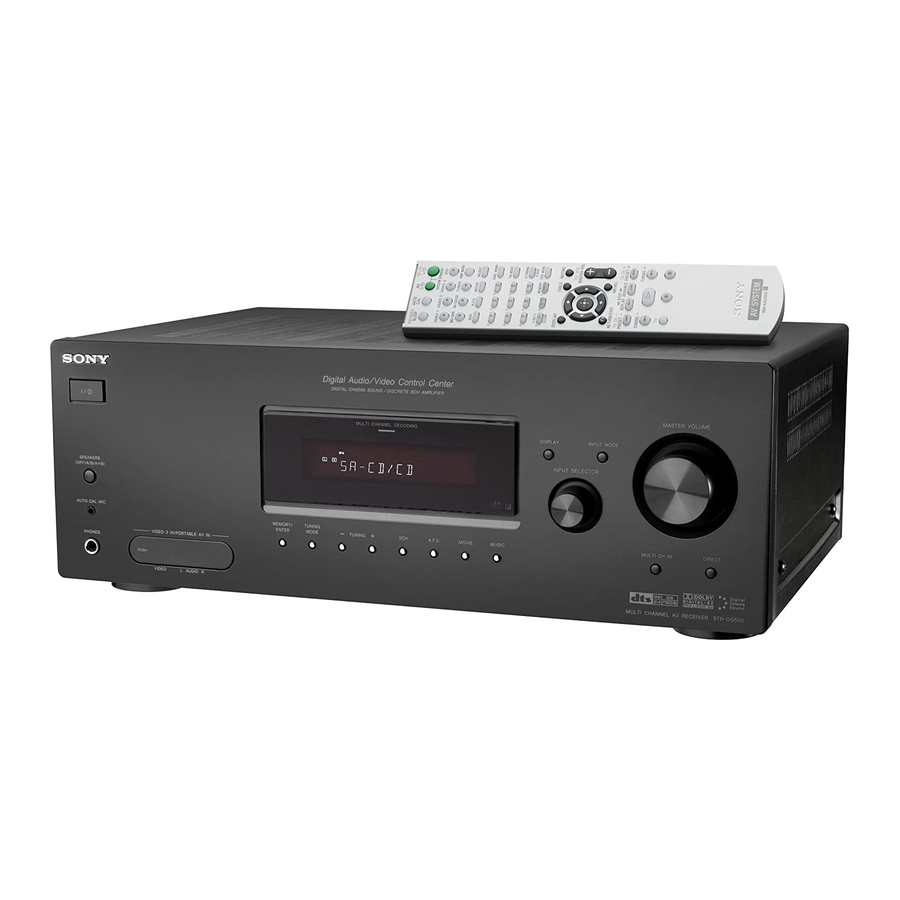
Getting Started Description and location of parts Front panel SPEAKERS (OFF/A/B /A+B) AUTO CAL MIC VIDEO 3 IN/PORTABLE AV IN PHONES VIDEO L AUDIO R To remove the cover Press PUSH. When you remove the cover, keep it out of reach from children. - Page 6 Name Function F DISPLAY Press to select information displayed on the display (page 59, 62). G INPUT MODE Press to select the input mode when the same components are connected to both digital and analog jacks (page 60). H MASTER Turn to adjust the volume VOLUME level of all speakers at the...
- Page 7 About the indicators on the display SP A DIGITAL EX SP B SLEEP OPT COAX SL S SR Name Function A SW Lights up when sub woofer selection is set to “YES” (page 37) and the audio signal is output from the SUB WOOFER jack.
- Page 8 Name Function H MEMORY Lights up when a memory function, such as Preset Memory (page 57), etc., is activated. I A.DIRECT Lights up when ANALOG DIRECT is selected (page 52). J Preset Lights up when using the station receiver to tune in radio stations indicators you have preset.
-
Page 9: Rear Panel
Rear panel DIGITAL OPTICAL VIDEO 1 ANTENNA VIDEO 2 VIDEO IN COAXIAL AUDIO IN SA-CD/CD MD/TAPE A DIGITAL INPUT section OPTICAL Connects to a DVD IN jack player, etc. The COAXIAL jack provides a better COAXIAL IN quality of loud jack sound (page 20, 22). -
Page 10: Video Input
(page 19). Remote commander You can use the supplied remote RM-AAU005 Connects to a DVD to operate the receiver and to control the Sony player, TV, or a satellite tuner. You audio/video components that the remote is can enjoy high assigned to operate (page 64). - Page 11 Name Function B TV ?/1 Press TV ?/1 and TV (M) at the same time to turn the TV on or off. Press to turn the receiver on or off. To turn off all components, press ?/1 and AV ?/1 (A) at the same time (SYSTEM STANDBY).
- Page 12 When you press any of the input buttons, the receiver turns on. The buttons are factory assigned to control Sony components as follows. You can change the button assignments following the steps in “Changing button assignments” on page 64.
-
Page 13: 1: Installing Speakers
1: Installing speakers This receiver allows you to use a 6.1 channel system (6 speakers and one sub woofer). Enjoying a 5.1/6.1 channel system To fully enjoy theater-like multi channel surround sound requires five speakers (two front speakers, a center speaker, and two surround speakers) and a sub woofer (5.1 channel). -
Page 14: 2: Connecting Speakers
2: Connecting speakers VIDEO IN VIDEO IN VIDEO OUT VIDEO IN AUDIO IN AUDIO IN AUDIO OUT AUDIO IN SA-CD/CD MD/TAPE VIDEO 2 VIDEO 1 A Monaural audio cord (not supplied) B Speaker cords (not supplied) AFront speaker A (L) BFront speaker A (R) CCenter speaker DSurround speaker (L) -
Page 15: 3A: Connecting The Audio Components
3a: Connecting the audio components How to hook up your components This section describes how to hook up your components to this receiver. Before you begin, refer to “Component to be connected” below for the pages which describe how to connect each component. -
Page 16: Connecting Components With Multi Channel Output Jacks
Connecting components with multi channel output jacks If your DVD or Super Audio CD player is equipped with multi channel output jacks, you can connect it to the MULTI CH IN jacks of this receiver to enjoy multi channel sound. Alternatively, the multi channel input jacks can be used to connect an external multi channel decoder. - Page 17 Connecting components with analog audio jacks The following illustration shows how to connect a component which has analog jacks such as tape deck, etc. Super Audio CD player/ CD player DIGITAL OPTICAL VIDEO 1 ANTENNA VIDEO 2 COAXIAL SA-CD/CD A Audio cord (not supplied) MD deck/ Tape deck COMPONENT VIDEO...
-
Page 18: 3B: Connecting The Video Components
3b: Connecting the video components How to hook up your components This section describes how to hook up your components to this receiver. Before you begin, refer to “Component to be connected” below for the pages which describe how to connect each component. -
Page 19: Tv Monitor
Hooking up a TV monitor The image from a visual component connected to this receiver can be displayed on a TV screen. It is not necessary to connect all the cables. Connect video cords according to the jacks of your components. DIGITAL OPTICAL VIDEO 1... -
Page 20: Dvd Player/Dvd Recorder
Hooking up a DVD player/DVD recorder The following illustration shows how to connect a DVD player/DVD recorder. It is not necessary to connect all the cables. Connect audio and video cords according to the jacks of your components. 1 Connecting audio DVD player DIGITAL OPTICAL... -
Page 21: Connecting Video
2 Connecting video DIGITAL OPTICAL VIDEO 1 ANTENNA VIDEO 2 COAXIAL SA-CD/CD MD/TAPE A Video cord (not supplied) B Component video cord (not supplied) If you connect a DVD recorder • Be sure to change the factory setting of the VIDEO 1 input button on the remote so that you can use the button to control your DVD recorder. -
Page 22: Satellite Tuner
Hooking up a satellite tuner The following illustration shows how to connect a satellite tuner. It is not necessary to connect all the cables. Connect audio and video cords according to the jacks of your components. DIGITAL OPTICAL VIDEO 1 ANTENNA VIDEO 2 COAXIAL... -
Page 23: Vcr
Hooking up components with analog video and audio jack The following illustration shows how to connect a component which has analog jacks such as a VCR, etc. DIGITAL OPTICAL VIDEO 1 ANTENNA VIDEO 2 COAXIAL SA-CD/CD MD/TAPE To the VIDEO 3 IN/PORTABLE AV IN jacks Camcorder/ video game A Audio/video cord (not supplied) -
Page 24: 4: Connecting The Antennas
4: Connecting the antennas Connect the supplied AM loop antenna and FM wire antenna. FM wire antenna (supplied) DIGITAL OPTICAL VIDEO 1 ANTENNA VIDEO 2 COAXIAL * The shape of the connector varies depending on the area code of this receiver. Notes •... -
Page 25: 5: Preparing The Receiver And The Remote
5: Preparing the receiver and the remote Setting the voltage selector If your receiver has a voltage selector on the rear panel, check that the voltage selector is set to the local power supply voltage. If not, use a screwdriver to set the selector to the correct position before connecting the AC power cord to a wall outlet. -
Page 26: 6: Selecting The Speaker System
Inserting batteries into the remote Insert two R6 (size-AA) batteries in the RM-AAU005 remote commander. Observe the correct polarity when installing batteries. Notes • Do not leave the remote in an extremely hot or humid place. • Do not use a new battery with old ones. •... -
Page 27: 7: Calibrating The Appropriate Settings Automatically (Auto Calibration)
7: Calibrating the appropriate settings automatically (AUTO CALIBRATION) This receiver is equipped with D.C.A.C. (Digital Cinema Auto Calibration) Technology which allows you to perform automatic calibration as follows: • Check the connection between each speaker and the receiver. • Adjust the speaker level. •... -
Page 28: Error Codes
The table below shows the display when measurement starts. Measurement for Display Environment noise level NOISE.CHK Speaker connection MEASURE and SP DET. appears alternately* Speaker level MEASURE and GAIN appears alternately* Speaker distance MEASURE and DISTANCE appears alternately* * The corresponding speaker indicator lights up in the display during measurement. - Page 29 Warning codes During Auto Calibration, the warning code provides information on the measurement result. The warning code will appear on the display cyclically as follows: Warning code t blank display t (warning code t blank display) t PUSH t blank display t ENTER Appears when there are more than one warning code.
-
Page 30: 8: Adjusting The Speaker Levels And Balance (Test Tone)
8: Adjusting the speaker levels and balance (TEST TONE) You can adjust the speaker levels and balance while listening to the test tone from your listening position. The receiver employs a test tone with a frequency centered at 800 Hz. VIDEO 1 VIDEO 2 VIDEO 3 MD/TAPE SA-CD/CD TUNER AMP MENU A.F.D. -
Page 31: Playback
Playback Selecting a component SYSTEM STANDBY VIDEO 1 VIDEO 2 VIDEO 3 MD/TAPE SA-CD/CD TUNER AMP MENU A.F.D. MOVIE MUSIC DUAL MONO FM MODE D.TUNING D.SKIP >10/ MEMORY DVD MENU 0/10 ENTER CLEAR MUTING DISPLAY TOOLS TV VOL MASTER VOL RETURN/EXIT MENU TV CH –... -
Page 32: Listening/Watching A Component
< > TUNING – TUNING + Notes • The operation is described for a Sony Super Audio CD player. • Refer to the operating instructions supplied with the Super Audio CD player or CD player. Tips • You can select the sound field to suit the music. -
Page 33: Watching A Dvd
Watching a DVD TV ?/1 TV/VIDEO AUTO SLEEP SYSTEM STANDBY VIDEO 1 VIDEO 2 VIDEO 3 MD/TAPE SA-CD/CD TUNER AMP MENU A.F.D. MOVIE MUSIC DUAL MONO FM MODE D.TUNING D.SKIP MEMORY DVD MENU >10/ 0/10 ENTER CLEAR DISPLAY TOOLS MUTING TV VOL MASTER VOL RETURN/EXIT... -
Page 34: Amplifier Operations
Amplifier Operations Navigating through menus By using the amplifier menus, you can make various adjustments to customize the receiver. VIDEO 1 VIDEO 2 VIDEO 3 MD/TAPE SA-CD/CD TUNER AMP MENU A.F.D. MOVIE >10/ MEMORY DVD MENU 0/10 ENTER CLEAR DISPLAY TOOLS RETURN/EXIT MENU... -
Page 35: Overview Of The Menus
Overview of the menus The following options are available in each menu. For details on navigating through menus, see page 34. Menu Parameters [Display] [Display] LEVEL (38) Test tone [T. TONE] [1-LEVEL] Front speaker balance [FRT BAL] Center speaker level [CNT LVL] Surround left speaker level [SL LVL]... -
Page 36: Video 2
Menu Parameters [Display] [Display] TUNER (41) FM station receiving mode [4-TUNER] [FM MODE] Naming preset stations [NAME IN] AUDIO (41) Digital audio input decoding [5-AUDIO] priority [DEC. PRI.] Digital broadcast language selection A/V Sync Naming inputs VIDEO (42) Component video assign [6-VIDEO] [COMP. - Page 37 Menu Parameters [Display] [Display] SYSTEM (43) Sub woofer [7-SYSTEM] [SW SPK] Front speakers [FRT SPK] Center speakers [CNT SPK] Surround speakers [SUR SPK] Surround back speaker [SB SPK] Front speaker distance [FRT DIST.] Center speaker distance [CNT DIST.] Surround left speaker a)b) distance [SL DIST.]...
-
Page 38: Adjusting The Level (Level Menu)
Adjusting the level (LEVEL menu) You can use the LEVEL menu to adjust the balance and level of each speaker. These settings are applied to all sound fields. Select “1-LEVEL” in the amplifier menus. For details on adjusting the parameters, see “Navigating through menus”... -
Page 39: Adjusting The Tone (Tone Menu)
Adjusting the tone (TONE menu) You can use the TONE menu to adjust the tonal quality (bass/treble level) of the front speakers. These settings are applied to all sound fields. Select “2-TONE” in the amplifier menus. For details on adjusting the parameters, see “Navigating through menus”... - Page 40 Using the surround back decoding mode (SUR BACK DECODING) By decoding the surround back signal of DVD software (etc.) recorded in Dolby Digital Surround EX, DTS-ES Matrix, DTS-ES Discrete 6.1, etc., format, you can enjoy the surround sound intended by the filmmakers. Select the surround back decoding mode using “SB DEC”...
-
Page 41: Settings For The Tuner (Tuner Menu)
Settings for the tuner (TUNER menu) You can use the TUNER menu to set the FM station receiving mode and to name preset stations. Select “4-TUNER” in the amplifier menus. For details on adjusting the parameters, see “Navigating through menus” (page 34) and “Overview of the menus”... -
Page 42: Settings For The Video (Video Menu)
x DUAL (Digital broadcast language selection) Lets you select the language you want to listen to during digital broadcast. This feature only functions for Dolby Digital sources. • DUAL M/S (Main/Sub) Sound of the main language will be output through the front left speaker and sound of the sub language will be output through the front right speaker simultaneously. -
Page 43: Settings For The System (System Menu)
Settings for the system (SYSTEM menu) You can use the SYSTEM menu to set the size and distance of the speakers connected to this system. Select “7-SYSTEM” in the amplifier menus. For details on adjusting the parameters, see “Navigating through menus” (page 34) and “Overview of the menus”... - Page 44 x SUR SPK (Surround speakers) The surround back speaker will be set to the same setting. • LARGE If you connect large speakers that will effectively reproduce bass frequencies, select “LARGE”. Normally, select “LARGE”. However, if the front speakers are set to “SMALL”, you cannot set the surround speakers to “LARGE”.
-
Page 45: Speaker Distance
x SL DIST. (Surround left speaker distance) Lets you set the distance from your listening position to the surround left speaker. Surround left speaker distance should be set from a distance equal to the front speaker distance (A) to a distance 4.5 meters (15 feet) closer to your listening position (C). - Page 46 • SIDE/LO Select if the location of your surround speakers corresponds to sections A and C. • SIDE/HI Select if the location of your surround speakers corresponds to sections A and D. • BEHD/LO Select if the location of your surround speakers corresponds to sections B and C.
-
Page 47: Calibrating The Appropriate Settings Automatically (A. Cal Menu)
Calibrating the appropriate settings automatically (A. CAL menu) For details, see “7: Calibrating the appropriate settings automatically (AUTO CALIBRATION)” (page 27). Enjoying Surround Sound Enjoying Dolby Digital and DTS Surround sound (AUTO FORMAT DIRECT) The Auto Format Direct (A.F.D.) mode allows you to listen to higher fidelity sound and select the decoding mode for listening to a 2 channel stereo sound as multi channel sound. - Page 48 Types of A.F.D. mode Decoding A.F.D. mode mode [Display] (Detecting A.F.D. AUTO automatically) [A.F.D. AUTO] Dolby Pro Logic PRO LOGIC [DOLBY PL] Dolby Pro Logic PRO LOGIC II MOVIE [PLII MV] PRO LOGIC II MUSIC [PLII MS] PRO LOGIC II GAME [PLII GM] Dolby Pro Logic PRO LOGIC IIx MOVIE...
-
Page 49: Selecting A Pre-Programmed Sound Field
If you connect a sub woofer This receiver will generate a low frequency signal for output to the sub woofer when there is no LFE signal, which is a low-pass sound effect output from a sub woofer to a 2 channel signal. - Page 50 [HP MULTI] HEADPHONE THEATER DCS [HP THEA] Effect Reproduces the sound characteristics of the Sony Pictures Entertainment “Cary Grant Theater” cinema production studio. This is a standard mode, great for watching almost any type of movie. Reproduces the sound characteristics of the Sony Pictures Entertainment “Kim Novak Theater”...
- Page 51 Sound fields with DC S mark use DCS technology. DCS is a unique sound reproduction technology for home theater developed by Sony, in cooperation with Sony Pictures Entertainment, for enjoying the exciting and powerful sound of movie theaters at home. With this “Digital Cinema Sound” developed...
-
Page 52: Using Only The Front Speakers (2Ch Stereo)
Using only the front speakers (2CH STEREO) In this mode, the receiver outputs the sound from the front left/right speakers only. There is no sound from the sub woofer. Standard 2 channel stereo sources completely bypass the sound field processing and multi channel surround formats are downmixed to 2 channel. -
Page 53: Resetting Sound Fields To The Initial Settings
Resetting sound fields to the initial settings Be sure to use the buttons on the receiver for this operation. MULTI CHANNEL DECODING SPEAKERS (OFF/A/B /A+B) AUTO CAL MIC MEMORY/ TUNING ENTER MODE TUNING A.F.D. MOVIE MUSIC VIDEO 3 IN/PORTABLE AV IN PHONES VIDEO L AUDIO R... -
Page 54: Automatic Tuning
Automatic tuning VIDEO 1 VIDEO 2 VIDEO 3 MD/TAPE SA-CD/CD TUNER AMP MENU A.F.D. MOVIE MUSIC DUAL MONO FM MODE D.TUNING D.SKIP >10/ MEMORY DVD MENU 0/10 ENTER CLEAR MUTING DISPLAY TOOLS TV VOL MASTER VOL RETURN/EXIT MENU TV CH – TV CH + PRESET –... -
Page 55: Storing Fm Stations Automatically (Autobetical)
Press ENTER. You can also use MEMORY/ENTER on the receiver. If you cannot tune in a station Make sure you have entered the right frequency. If not, repeat steps 2 to 4. If you still cannot tune in a station, the frequency is not used in your area. -
Page 56: Presetting Radio Stations
Hold down MEMORY/ENTER and press ?/1 to turn the receiver back on. “AUTO-BETICAL SELECT” appears on the display and the receiver scans and stores all the FM and FM RDS stations in the broadcast area. For RDS stations, the tuner first checks for stations broadcasting the same program, then stores only the ones with the clearest signal. -
Page 57: Tuning To Preset Stations
Press MEMORY. You can also use MEMORY/ENTER on the receiver. “MEMORY” lights up for a few seconds. Perform steps 4 and 5 before “MEMORY” goes out. Press the numeric buttons to select a preset number. You can also press TUNING + or TUNING –... -
Page 58: Naming Preset Stations
Naming preset stations VIDEO 1 VIDEO 2 VIDEO 3 MD/TAPE SA-CD/CD TUNER AMP MENU A.F.D. MOVIE >10/ MEMORY DVD MENU 0/10 ENTER CLEAR DISPLAY TOOLS RETURN/EXIT MENU Press TUNER repeatedly to select the FM or AM band. You can also use INPUT SELECTOR on the receiver. -
Page 59: Using The Radio Data System (Rds)
Using the Radio Data System (RDS) (Models of area code CEL, CEK only) This receiver also allows you to use RDS (Radio Data System), which enables radio stations to send additional information along with the regular program signal. You can display RDS information. -
Page 60: Other Operations
Program type Description indication VARIED Other types of programs such as celebrity interviews, panel games, and comedy POP M Popular music programs ROCK M Rock music programs EASY M Easy Listening LIGHT M Instrumental, vocal, and choral music CLASSICS Performances of major orchestras, chamber music, opera, etc. -
Page 61: Watching Component Images From Other
Watching component images from other inputs (COMPONENT VIDEO ASSIGN) You can reassign a component video input to another input. Press AMP MENU. “1-LEVEL” appears on the display. Press control button V/v repeatedly to select “6-VIDEO”. Press the control button or control button b to enter the menu. -
Page 62: Naming Inputs
Naming inputs You can enter a name of up to 8 characters for inputs and display it on the receiver’s display. This is convenient for labeling the jacks with the names of the connected components. Press the input button to select the input you want to create an index name for. -
Page 63: Using The Sleep Timer
Using the Sleep Timer You can set the receiver to turn off automatically at a specified time. Press SLEEP repeatedly while the power is on. Each time you press the button, the display changes cyclically as follows: 1-30-00 t 1-00-00 t 0-30-00 2-00-00 t t OFF When Sleep Timer is being used, “SLEEP”... -
Page 64: Using The Remote
Recording onto a recording media You can record from a video component using the receiver. See the operating instructions supplied with your recording component. Press one of the input buttons to select the playback component. You can also use INPUT SELECTOR on the receiver. -
Page 65: Glossary
Tuner (this receiver) DVR (Digital CATV terminal) DSS (Digital Satellite Receiver) Sony VCRs are operated with a VTR 2 or VTR 3 setting which correspond to 8 mm and VHS respectively. Sony DVD recorders are operated with a DVD1 or DVD3 setting. -
Page 66: Dolby Pro Logic Ii
x Dolby Pro Logic II This technology converts 2ch stereo recorded audio into 5.1ch for playback. There is a MOVIE mode for movies and MUSIC mode for stereo sources such as music. Old movies encoded in the traditional stereo format can be enhanced with 5.1ch surround sound. -
Page 67: Precautions
Do not use any type of abrasive pad, scouring powder, or solvent, such as alcohol or benzine. If you have any questions or problems concerning your receiver, please consult your nearest Sony dealer. -
Page 68: Troubleshooting
Troubleshooting If you experience any of the following difficulties while using the receiver, use this troubleshooting guide to help you remedy the problem. There is no sound, no matter which component is selected, or only a very low-level sound is heard. •... - Page 69 There is severe hum or noise. • Check that the speakers and components are connected securely. • Check that the connecting cords are away from a transformer or motor, and at least 3 m (10 feet) away from a TV set or fluorescent light.
-
Page 70: Remote Control
You can check the condition of the system by the message. Refer to the following table to solve the problem. If any problem persists, consult your nearest Sony dealer. If an error message appears while you perform Auto Calibration, see “Error and warning codes”... -
Page 71: Specifications
If the problem persist Consult your nearest Sony dealer. Reference sections for clearing the receiver’s memory To clear All memorized settings... - Page 72 Models of area code AR, KR Stereo Power Output , Reference Power 1)2) Output 8 ohms 20 Hz – 20 kHz, THD 0.09% 85 W + 85 W 70 W + 70 W 8 ohms 1 kHz, THD 0.7% 100 W + 100 W 90 W + 90 W 8 ohms 1 kHz, THD 10% 125 W + 125 W...
- Page 73 AM tuner section Tuning range Area code Tuning scale 10 kHz step 9 kHz step U, CA 530 – 1,710 kHz 530 – 1,610 kHz CEL, CEK, AU, – TW, KR, TH6, SP 530 – 1,610 kHz Intermediate frequency 450 kHz Usable sensitivity 50 dB µ/m (at 1,000 kHz or 999 kHz)
-
Page 74: Index
Index Numerics 2 channel 52 2CH STEREO 52 5.1 channel 13 6.1 channel 13 AUTO CALIBRATION 27 AUTO FORMAT DIRECT (A.F.D.) 47 AUTOBETICAL 55 CD player connecting 15 playback 32 COMPONENT VIDEO ASSIGN 61 Digital Cinema Sound (DCS) 51 Dolby Digital 65 DTS 66 DVD player hooking up 18... - Page 76 Sony Corporation Printed in Malaysia...