
Related Manuals for Elster gas-lab Q1


Summary of Contents for Elster gas-lab Q1
- Page 1 Gas quality analyser Q1 Technical documentation Function, operation, commissioning and maintenance FCQ1-BAShort-EN a 19.3.2013 2013 Elster GmbH Edition a 19.3.2013...
- Page 2 Copyright 2013 Elster GmbH GAS-WORKS, Z1, gas-lab Q1, and FLOW COMP are German registered trademarks of Elster. Microsoft, Windows and Windows NT are registered trademarks of Microsoft Corporation. HART is a registered trademark of HART Communication Foundation. Elster GmbH Schlossstraße 95a D - 44357 Dortmund, Germany Tel.: +49 231 937110-0...
-
Page 3: Table Of Contents
GAS-WORKS / GW-GNET+ ..............97 Compiling and exporting a parameterisation: Brief description ..98 Importing and editing a parameterisation: Brief description ..... 101 Extras: GW-GNET+ service programs ..........103 Optional: GW-Remote+ for downloading archives ......105 gas-lab Q1 Page iii... - Page 4 Commissioning of Integrated RDT module ........122 Commissioning the sensor system ..........123 Maintenance ..................125 Maintaining the gas-net Q1 evaluation computer ......125 Maintaining the gas-lab Q1 sensor system ........128 Technical data: Q1 ................129 10.1 Device type ..................129 10.2...
-
Page 5: Safety And Warning Notes
– Part 17: Inspection and maintenance of electrical installations in hazardous areas (other than mines) DIN VDE 0100-610, Publication date: 1994-04, Erection of power installations with nominal voltages up to 1000 V; initial verification gas-lab Q1 Page v... - Page 6 -20°C nor above +55°C. Connect the electrical cables only to the EEx-e approved junction box! This junction box is located on the mounting plate of the gas-lab Q1. The sensor system is supplied by 24 V DC and must be secured externally by 2.5 A.
- Page 7 The sensor system may only be switched on before or together with the gas-net Q1 evaluation computer. It will result in an error (alarm) if you switch on the sensor system after having switched on the evaluation computer. gas-lab Q1 Page vii...
- Page 8 Warning: The evaluation computer of the Q1 measuring system is a class A device that may cause interferences in living areas; in this case, the user may be asked for appropriate measures at his expense. Page viii gas-lab Q1...
-
Page 9: Introduction
1.1 The gas-net system idea is the generic term for an Elster device family. The evaluation computer of the gas-lab Q1, too, is based on the gas-net device family. All gas-net devices, including future device types, are characterised by uniformity in appearance, operation and parameterisation. - Page 10 The evaluation computer also controls the measuring process and calculates the target variables. Non-hazardous area RS422 / optical fibre converter gas-net optical fibre evaluation computer gas-lab Q1 sensor system Sensor unit Communi- Sensor cations elektronics Double-block&bleed RS422, valve set...
- Page 11 The device measures continually and determines new measurements every second. It can therefore also be used for fast closed-loop control tasks. The manufacturer calibrates the gas-lab Q1 before delivery, i.e. he performs a zero point adjustment with nitrogen and afterwards a 3-point calibration with ultra-pure methane and two calibration gases.
-
Page 13: Device View And Design
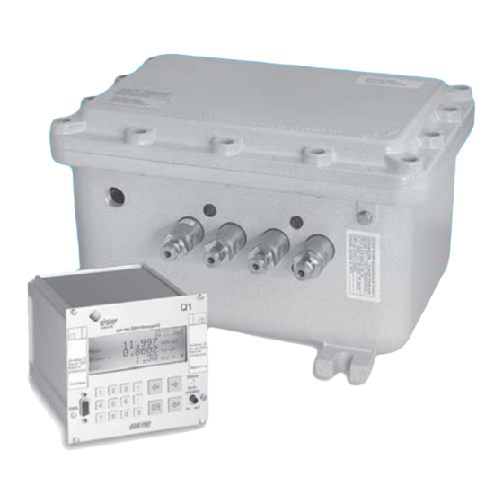
2 Device view and design 2.1 Sensor system The actual sensor technology of the gas-lab Q1, the sensor system, is mounted in an explosion-proof housing. The gas is supplied at approximately 80 mbars overpressure and via a double block & bleed solenoid valve set, which is also located inside the housing. - Page 14 Q1 Not only the sensor housing is installed on the mounting plate, but also regulators for the inlet pressure of the different gases to be injected, safety shut- off and safety relief valves as well as the EEx-e junction box for the interconnecting cables (voltage supply, data link to the evaluation computer).
-
Page 15: Evaluation Computer
The following illustration shows, as an example, the front view of a gas-net Q1 in the narrow design with a mounting width of 1/3: Display gas-lab Gas Quality Meter Data Status LED interface Status Calibration switch Cal.- switch close open Key pad gas-lab Q1 Page 7... - Page 16 An MSER2 board with 2 serial channels (RS232, RS422 or RS485) for interfacing communication protocols (e.g. MODBUS). An MFE11 input board with 8 digital and 3 analogue inputs. An MFA6 output board with 4 digital and 2 analogue outputs. Page 8 gas-lab Q1...
- Page 17 I1-I3: Three analog outputs for measurement output. gas-net input or output board can be assigned to board locations 1 or 2. Board 1 Board 2 Board 3 HS-Bus internal 0,63 ATT LMFA7 DCF77 gas-net Q1 rear view (example) gas-lab Q1 Page 9...
-
Page 19: Operating Gas-Net Devices
In some cases you may also trigger actions or change values via the navigation keys. The illustration below shows an overview of the keys’ meanings. The exact context-related meaning of each navigation key will be explained in connection with the menu structure in Section 3.4. gas-lab Q1 Page 11... -
Page 20: Other Operating Elements: Status Led, Calibration Switch
It can be removed from the error listing by accepting it. A warning has been pending but is no longer relevant. yellow, steady light It can be removed from the error listing by accepting it. The device runs error-free. green, steady light Page 12 gas-lab Q1... - Page 21 Open locks allow the user to access certain parameters or actions. All parameters being subject to the user locks can be changed when both locks are or the calibration switch is open. . gas-lab Q1 Page 13...
-
Page 22: Display
Each module has a main display in which all important current values are indicated. For example: Among others, the gas-net Q1 contains the gas-lab Q1 and Monitoring modules. The main display of the gas-lab Q1 module shows the current measurements, whereas the main display of the Monitoring module indicates the error listing. - Page 23 The menu structure is aborescent: A subordinated menu item of a module can offer subordinated menu items by himself. A Dialog is a display window indicating values that can be changed by the operator. gas-lab Q1 Page 15...
- Page 24 Start: Basic display Gas quality Menu list of the module Gas quality. The hyphen in front of the menu descriptions indicates that the list refers to subordinated menus. Page 16 gas-lab Q1...
- Page 25 Press the rightward arrow key several times until the module is selected, that you want to see. In our example it’s the Monitoring module. Module list: Monitoring module is selected Then press the Enter key and the display of the just selected module will be invoked. gas-lab Q1 Page 17...
- Page 26 This way, the user is forced to correct the value he has entered. Page 18 gas-lab Q1...
- Page 27 Start: Display Single message Value to be modified is selected. The currently set value is indicated. Switch to the edit mode via the Enter key. Edit mode: The insertion mark is now blinking behind the value. gas-lab Q1 Page 19...
- Page 28 If you confirm OK by pressing the Enter key, the new value will be accepted. To reject the modification, go to Cancel by pressing the rightward arrow key and afterwards the Enter key. You will quit the dialog in both cases. Page 20 gas-lab Q1...
- Page 29 On entering the display this switch is already activated, so you can press the Enter key right now to switch to the edit mode. Selective list: All applicable values are offered. (Here: off and on) gas-lab Q1 Page 21...
- Page 30 Invoke the menu now: Options on leaving Acceptance or rejection of the changed values. If you confirm OK the new value will be accepted. To reject the modification, go to Cancel and press the Enter key afterwards. Page 22 gas-lab Q1...
- Page 31 After having edited all values, press the Menu key. The invoked menu contains the menu items OK and Cancel. Selecting OK means accepting the modified values. Selecting Cancel means rejecting the changes. In both cases you will return to the display you invoked last. gas-lab Q1 Page 23...
-
Page 33: Primer For Impatient Operators: What Do I Have To Do To
Monitoring module’s message processing is also available. Always switch to the display of the next error listing via the Next listing menu item. Please refer to Chapter 5.3 for further information on the error listing of the message processing. gas-lab Q1 Page 25... -
Page 34: Accept The Gas Quality Measurement Errors
Repeat the steps explained above to accept further errors. Note: Accepting errors as described above only refers to errors in connection with the device’s gas quality functions. How to accept messages of the general message processing (Monitoring error listing) is explained in Chapter 5.3. Page 26 gas-lab Q1... -
Page 35: Check All Parameter Settings
The current status of the protection mechanisms (calibration switch / user lock) is of course taken into consideration. Please refer to the GW-GNET+ comprehensive online help for further information. gas-lab Q1 Page 27... -
Page 36: Check The Input Values
Select exactly the archive information you want to view in the appearing dialog. By the way it’s more comfortable to view the archives with the PC- Software. Please refer to Chapter 5.2.2 for a detailed description of the function. Page 28 gas-lab Q1... -
Page 37: Functional Description
Functional description 5 Functional description 5.1 Gas quality module The gas-lab Q1 measuring system is a device for measuring the gas quality of natural gas. It measures the infrared absorption of hydrocarbons and carbon dioxide (CO ) and also the thermal conductivity. The following variables are directly determined based on these measurements: Hs –... - Page 38 Indication of the error with Time and date the highest priority level Final values for GCV – gross calorific value, standard density, concentration Page 30 gas-lab Q1...
- Page 39 CO2’ are corrected values used in the automatic adjustment by means of a process gas chromatograph (PGC). The values satHon and sat Hun are the GCV and NCV in case of saturated concentration of H O for the defined reference condition. At last the density ratio is displayed. gas-lab Q1 Page 31...
- Page 40 Further- more the current state of measurement is indicated. All other values are intended for service and maintenance purposes. If you have questions for them please contact Elster. Page 32 gas-lab Q1...
- Page 41 (see 5.1.5). Also the corresponding shut-off valve must be opened. It is not necessary to open the calibration switch at the gas-lab Q1 for this calibration type. An automatic 1-point calibration with methane can be carried out during normal...
- Page 42 Invoke the menu from the basic display and select Calibration. Confirm selection invoke menu again. Then select Cal. Cancel and confirm the selection The gas-lab Q1 terminates the calibration process and returns to normal operation. Page 34 gas-lab Q1...
- Page 43 Functional description The process will be aborted automatically if an alarm occurs during calibration. Afterwards, the gas-lab Q1 uses the previous calibration data, provided such data exists. To manually start the 1-point calibration, do so by keeping to the following instruction sequences: Invoke the menu from the basic display select Calibration and confirm.
- Page 44 After confirming the calibration with methane proceeds automatically, whereas the remaining time is displayed. This process starts after approx. 2 minutes for purging and lasts for 10 minutes. Page 36 gas-lab Q1...
- Page 45 The new correction values determined during the calibration are written to the calibration archive. We also recommend observing the deviations of the automatic 1-point calibration in the quality archive. If these values are getting too high, a new basic calibration should be performed. gas-lab Q1 Page 37...
- Page 46 Although it runs automatically, the process steps are supported via the operator panel of the evaluation computer. The calibration switch at the gas-lab Q1 must be open to facilitate a basic calibration. The following reactions of the evaluation computer are indicating the status of...
- Page 47 By confirming the selection the gas-lab Q1 terminates the calibration process. The process will be aborted automatically if an alarm occurs during calibration. Afterwards, the gas-lab Q1 uses the same calibration data as before, provided such data exists. The basic calibration consists of the following steps:...
- Page 48 Connect the high-pressure tube to the third gas path of the sensor system finally For performing a basic calibration the gas-lab Q1 needs to know the exact com- position of the used calibration gases also. For that purpose the gas analysis of the used calibration gases has to be entered in the actual parameterization.
- Page 49 By pressing the menu key again, the following submenu appears. Select the menu item 3P-cal. start and confirm. Now the actual status of the 3-point calibration is indicated on the display. Here e. g.: The required operation – switch on gas (nitrogen channel 3) gas-lab Q1 Page 41...
- Page 50 It will not count down beforet 2 minutes of flushing time. Calibration with methane (1. calibration gas) Now the prepared methane has to be switched on, which the following display indicates: Please invoke the menu and select the menu item gas switched on. Page 42 gas-lab Q1...
- Page 51 (1. calibration gas) is finished, the following display appears: Calibration with H2-11K (2. calibration gas) Now the prepared H2-11K has to be switched on. Please invoke the menu and select the menu item gas switched on. gas-lab Q1 Page 43...
- Page 52 Calibration with L1-8K or binary gas mixture (3. calibration gas) Now the prepared L1-8K or binary gas mixture has to be connected. (see step 1. Preparation)Then the prepared 3rd calibration gas is started by opening the menu and selecting the menu item gas switched on. Page 44 gas-lab Q1...
- Page 53 After the basic calibration is finished, the sensor system automatically switches back to the process gas and starts measuring. Now turn close the L1-8K or binary gas mixture cylinder and remove the tube on both sides. (Caution: Unpressurise the line first!) gas-lab Q1 Page 45...
- Page 54 Open the test gas cylinder. The cylinder regulator must be set to about 2 bars. Set the precision pressure regulator to approx. 80 mbars. Now purge the first or third gas path (see 5.1.5). Page 46 gas-lab Q1...
- Page 55 When gas path 1 was used, make sure that after the test gas injection the process gas is reconnected and opened to this path. Otherwise the test gas is handeled as process gas and the measurement results are mapped incorrectly. gas-lab Q1 Page 47...
- Page 56 Remove the cylinder connection from the cylinder and close the cylinder with the corresponding nut. Place the protective cap on the cylinder and fasten it.. Not until now detach the protection against falling down (safety chain or clamp) and remove the cylinder. Page 48 gas-lab Q1...
- Page 57 14. Pay attention to the fact that the gas cylinder must be open finally to make a calibration or measurement possible. gas-lab Q1 Page 49...
- Page 58 1 - 5 bars and the pressure of the downstream precision pressure regulator to 80 mbars. Press the key while menue being in the main display, select the purging command and confirm it by pressing the key enter. Gas-channel 1 appears on the display. Page 50 gas-lab Q1...
- Page 59 Press the menu key now and start the purge with OK or quit the dialog via Cancel. The purge lasts for about 7 minutes. display shows purging. After the purge has been finished automatically, the gas-lab Q1 starts measuring the process gas again. gas-lab Q1 Page 51...
- Page 60 Functional description 5.1.6 Revision The gas-lab Q1 sets the revision status in case of a zero point adjustment, a 3- point calibration or a test gas injection. A set revision status means that the gas quality is not measured under normal and proper operating conditions.
-
Page 61: Data Logging Module
The Quality archive logs 6 quality factors during each 1-point calibration. These factors provide information on the corrections that have been made during the individual calibrations with methane. The Quality archive has a depth of 365 entries. gas-lab Q1 Page 53... - Page 62 However, when changing the archive structure, you have to delete the old archives already existing in the device. The devices have already been provided with a pre-defined archive structure corresponding to the common requirements before delivery. Page 54 gas-lab Q1...
- Page 63 The archive type is selected at the beginning, i.e. it is backlit in black. Press the Enter key to get into the edit mode. A list opens up from which you may choose the desired archive type via the arrow keys. gas-lab Q1 Page 55...
- Page 64 Status stands for a bit string that provides an overview of the status of the gas quality measurement system according to the DSfG Regulations. The meaning of the individual bits is defined in the DVGW documentation Technische Spezifikation für DSfG- Realisierungen (see Bibliography). Page 56 gas-lab Q1...
- Page 65 1. The ordinal number for each further entry is increased by one. For instance, ordinal numbers are needed for the polling of archive data via DSfG. gas-lab Q1 Page 57...
- Page 66 View the data afterwards in a table or as diagram by means of the GW-XL+ program. The configuration of the data logging function is more comfortable via the PC-Software and therefore not described here. See the Online-Help for further questions. Page 58 gas-lab Q1...
-
Page 67: Monitoring Module
If a warning is no longer pending, i.e. it is no longer relevant, it can be accepted at the operator panel of the device and thus removed from the error listing. gas-lab Q1 Page 59... - Page 68 32 measurements. For each defined measurement the minimum and maximum values measured since the last reset are indicated. The operator can view these values together with the associated time marks on the display. Page 60 gas-lab Q1...
- Page 69 Hint limit gradient has been met. Note: All single messages referring to measurements are also pending if the associated input value is regarded as being disturbed. gas-lab Q1 Page 61...
- Page 70 Only if this is the case, the message will be entered in the error listing as soon as it begins. There is no acceptance required for single messages; they are automatically removed from the error listing when they end. Page 62 gas-lab Q1...
- Page 71 The DSfG data elements for message processing are included in the DSfG data element tree of the Control entity. Please ask FLOW COMP for a precise list of the supported or used DSfG data elements, when required. gas-lab Q1 Page 63...
- Page 72 When a group is marked with No acceptance required, the result of the centralized message is always the same as the result of the group message. In contrast to the group message, however, the no acceptance requiring centralized message is entered in error listing and logbook. Page 64 gas-lab Q1...
- Page 73 (= group message) Centralized message group marked acceptance required Acceptance Acceptance Acceptance Acceptance These groups with their centralized and group messages are intended to provide an overview of the plant conditions. gas-lab Q1 Page 65...
- Page 74 This means that the group neither generates held group nor group nor centralized messages. Nevertheless, the centralized message is still entered in the logbook and error listing. If the M-switch is set, the main signaller no longer takes the group into account. Page 66 gas-lab Q1...
- Page 75 The following illustration shows the behaviour of the main signaller in connection with the acceptance (in case of one involved group): Group Single message M1 Single message M2 Acceptance Acceptance Main signaller message gas-lab Q1 Page 67...
- Page 76 This way, the data is logged more often in case of quickly changing values. This option is also available for counter archives, which means you can specify that the data logging shall always start when a count value has increased by a defined difference. Page 68 gas-lab Q1...
- Page 77 Normal data logging will not be continued after the end of the last message until the group has been accepted explicitly, for the centralized message only ends in this case. gas-lab Q1 Page 69...
- Page 78 An alarm has the highest priority level, i.e. it is of greatest importance. A warning has a higher priority level than a hint. Cf. Chapter 5.3.1 for an explanation of the terms Alarm, Warning and Hint. Page 70 gas-lab Q1...
- Page 79 The next position shows an M-switch message if the maintenance switch has been activated. Then, all pending centralized messages of groups 1 to 32 are indicated. System messages are generated for the events Re-start performed, Supply voltage failure, New parameterisation, and Parameter changed. gas-lab Q1 Page 71...
- Page 80 Line before last: Minimum value since last resetting, with time mark. Last line: Maximum value since last resetting, with time mark. If the associated measurement is indicated as being disturbed, the display keeps showing the last valid value. In this case, however, the value is blinking. Page 72 gas-lab Q1...
- Page 81 If the centralized message of the invoked group is currently pending, the single message of the group that has begun first is indicated below Initial message. gas-lab Q1 Page 73...
- Page 82 Currently indicated single message of the group. A list with all messages existing in this group opens up if you press the Enter key. You may also switch to the indication of another single message of the group via this selection list. Page 74 gas-lab Q1...
- Page 83 Therefore, the counter constantly shows how many seconds of the minimum pending time are remaining. Only after the counter has reached 0, the status indication of the message will change from Off to On. gas-lab Q1 Page 75...
- Page 84 The Single messages display is basically identical with the display of the Groups – View menu described above. The parameterised limit value is indicated as additional information in case of a message derived from measurement monitoring. Page 76 gas-lab Q1...
- Page 85 The Disabled messages menu described here merely provides information. Please switch to the Single messages menu (see above) if you want to change the status of a single message (disabled / enabled). gas-lab Q1 Page 77...
-
Page 86: System Module
Besides that, there are further process boards providing input channels (see Chapter 7.2.2). The System module’s display offers a special menu for viewing the source, source value and final value of the input signal on the device display (see Chapter 5.4.2). Page 78 gas-lab Q1... - Page 87 DSfG (optional feature for the European market) DSfG is a digital interface especially developed for data communications between gas meters (such as gas-net devices). If you need further information, please contact your local agent. Please see www.elster.com gas-lab Q1 Page 79...
- Page 88 PTB time normal about DCF-77 radio signal. If you need further information, please contact your local agent. Please see www.elster.com According to the DSfG Specification: W811: Clock set new W820: Clock set old W812: Clock-synch failed Page 80 gas-lab Q1...
- Page 89 Enter key) and select the name of the desired input value from the appearing list. After you have confirmed your choice by pressing the Enter key, the display of the selected board will be invoked. gas-lab Q1 Page 81...
- Page 90 Enter key). A list with the names of all parameterised output channels appears. After you have chosen the desired output channel and have pressed the Enter key, the display of the selected channel will be invoked. Page 82 gas-lab Q1...
- Page 91 To quit the test mode, press the Menu key again and confirm the Test off menu item. Note: You may also quit the test mode by quitting the current display, for instance via Back or by selecting a different channel. gas-lab Q1 Page 83...
- Page 92 Among the „own participants” bus addresses (EADRs) lists the Q1 internal instances.. Menu known participants Menu line: Bus activityät: The Q1 can get an attention-Telegram If you need further information, please contact your local agent. Please see www.elster.com Page 84 gas-lab Q1...
- Page 93 It is also possible to change the status of just one lock. Press the Menu key after you have successfully entered the numerical lock(s). Open the locks with OK or leave them closed by confirming Cancel. gas-lab Q1 Page 85...
- Page 94 LED shows all three colours after each other. Finish the display test via Back. If the calibration switch is closed, resetting the clock is only permissible within a range of ± 20 seconds and only once within 24 hours. Page 86 gas-lab Q1...
-
Page 95: Integrated Rdt Module
The main display of the module Integrated RDT indicates in what state the RDT Optional feature for the European market and, not available with all software variants. If you need further information, please contact your local agent. Please see www.elster.com gas-lab Q1 Page 87... - Page 96 Optional feature for the European market and, not available with all software variants. Historie Menu RDT-statistics GSM (only when connected to a wireless modem) Optional feature for the European market If you need further information, please contact your local agent. Please see www.elster.com Page 88 gas-lab Q1...
-
Page 97: Dsfg Module, Data Exchange Module
The optional module controls the DSfG side of data exchange. If you need further information, please contact your local agent. Please see www.elster.com Typical protocols are, for instance, 3964R/RK512 (e.g. in case of Siemens S5/S7) or Modbus-RTU (e.g. in case of Cegelec Modicon). gas-lab Q1 Page 89... - Page 98 However, only after all of them have been collected again once more. Moreover, a job group may be linked with a trigger. A trigger is a defined position in the host and initiates a new processing of a job when its content has changed. Page 90 gas-lab Q1...
- Page 99 64 data words per transmission. This is why in the GW-GNET+ interface (Data exchange module) the positions for import and export values are not indicated in the DB/DW form but as serial register numbers. gas-lab Q1 Page 91...
- Page 100 RK512 response A maximum of 64 data words per telegram, no 3964R telegrams: response telegrams. In the RK512 slave operating mode (i.e. host = master), the gas-net device generates the response telegrams listed in the table below: Page 92 gas-lab Q1...
- Page 101 These register details always refer to the MODBUS telegram presentation. This may possibly lead to different register numbers in the PLC, depending on the host type. gas-lab Q1 Page 93...
- Page 102 03 (= read holding registers) or 16 (= preset multiple registers) are needed in the gateway; this is why only these are supported. illegal data address The indicated data address is not permissible. failure in associated Other device Page 94 gas-lab Q1...
- Page 103 The Error statistics subordinate menu shows the number and type of the communications errors that have been detected in case of the selected protocol channel. You may reset the error statistics manually via the operator panel (Clear statistics). gas-lab Q1 Page 95...
-
Page 105: Gas-Works / Gw-Gnet
For instance, you may exchange operational parts of the parameterisation in the GW-GNET+ Edit parameterisation mode, even if the calibration switch is closed. In the Change parameter mode, parameters characterised as changeable online can be edited without restarting the device. gas-lab Q1 Page 97... -
Page 106: Compiling And Exporting A Parameterisation: Brief Description
By double- clicking this box you activate a dialog box listing all parameters that belong to the module concerned. Adjust the settings according to your requirements. Page 98 gas-lab Q1... - Page 107 You will receive a corresponding message indicating which linkages you have to set up again afterwards to render the parameterisation consistent again. Detailed information is available in the GW-GNET+ online help. gas-lab Q1 Page 99...
- Page 108 Alternatively, drag the data record directly to a folder in the hierarchy (on the left side of the configuration window). Please refer to the GW-BASE User’s Guide or online help for more detailed information. Page 100 gas-lab Q1...
-
Page 109: Importing And Editing A Parameterisation: Brief Description
After you have entered the name and confirmed your entry by clicking OK, the reading in of the data will start. After the reading in has been finished, close the communication program via the main menu item File – Exit. gas-lab Q1 Page 101... - Page 110 GW-BASE worksheet in this case and must be filed away in a suitable hierarchy. Close GW-GNET+ and export the modified parameterisation as described in Chapter 6.1, steps 8 to 11. For brief instructions see footnote page 112. Page 102 gas-lab Q1...
-
Page 111: Extras: Gw-Gnet+ Service Programs
Delete archives Starts GW-REMOTE+ via the data interface, if installed. Facilitates data access to all devices connected via DSfG; for instance, for reading out DSfG bus access archive data and viewing current data. gas-lab Q1 Page 103... - Page 112 The function range of the service programs is manageable and practical. The operation is thus rather easy. A comprehensive online help is also available for each program. It can be activated via the Help – Content menu item or by pressing the F1 key. Page 104 gas-lab Q1...
-
Page 113: Optional: Gw-Remote+ For Downloading Archives
GW-BASE toolbar. After the data connection to the device has been established, the type plate of the connected device appears on the display. 4. Select the Contents tab. The appearing tab lists all available data. 5. Start Archives, Logbooks by double-clicking. gas-lab Q1 Page 105... - Page 114 The archive records are stored with the specified names in the GAS-WORKS worksheet. Before they couldl be displayed, these records must be transferred to the hierarchy. Records in the worksheet section could not directly be processed. For brief instructions see footnote page 112. Page 106 gas-lab Q1...
-
Page 115: Installation
50 mm can be guaranteed, which is required by the relevant guidelines. gas-lab Q1 Page 107... - Page 116 7.2.1 Power supply and protective earthing Operate the gas-lab Q1 with a nominal voltage of 24 V DC. The connection of 24 V is implemented via the terminals + and - on the back of the device, and must be externally protected against short circuits with 1 A.
- Page 117 Installation 7.2.2.1 Connection between sensor system and evaluation computer gas-lab Q1 Page 109...
- Page 118 For the sensors, only HART polling addresses from 1 to 4 are allowed; make sure that the addresses are unambiguous and that the address assignment corresponds to the assignment in the parameterisation of the gas- net device. Page 110 gas-lab Q1...
- Page 119 100 m. If the cable is longer, it must be guaranteed that the lines are installed separately from other conducting lines to avoid interferences. The cable shielding for all transmitter lines is connected to the SH terminal at the EXMFE4 input board. gas-lab Q1 Page 111...
- Page 120 RS422/RS485: Transmitted data (A) Signal ground Shield In the gas-lab Q1 the MSER2 board serves as protocol gateway functionality for the connection of a host computer. Notes: When RS422 and RS485 are used, a matching resistor of 120 ohms may be required in the receiver between RXB and RXA, depending on the cable length.
- Page 121 The AE12 input board offers 12 analogue inputs for the connection of measuring sensors with a 0/4..20 mA output signal. Connect the inputs via terminals I1+ to I12+ with the common ground I-. Connect the cable shielding to the SH terminal. gas-lab Q1 Page 113...
- Page 122 The terminals named LA and LE right at the top of the board are fibre-optics connections for an external I/O expansion (LA = fibre-optics output, LE = fibre- optics input). Connect the cable shielding to the SH terminal of the board. Page 114 gas-lab Q1...
- Page 123 COM connection (one-to-one connection) is not permissible. 7.2.3.2 DSfG interface Proprietary interface for the european market. If you need further information, please contact your local agent. Please see www.elster.com 7.2.3.3 HSB interface The HSB interface has currently no function at all. gas-lab Q1 Page 115...
- Page 124 The COM2 interface is a serial interface according to RS232 for RDT applications for the European market. If you need further information, please contact your local agent. Please see www.elster.com Assembling components Suitable antenna If you need further information, please contact your local agent. Please see www.elster.com Page 116 gas-lab Q1...
-
Page 125: Mounting The Sensor System
1 pressure gauge of connection connection inlet pressure for gas-lab Q1 gas-lab Q1 Page 117... - Page 126 7.3.3 Gas injection line The pipes for the process and calibration gases (methane) are connected to the respective low-pressure regulators (Elster M2R); usually these are stainless steel pipes with a 6-mm diameter. The inlet pressure must range between 1 to 5 bars overpressure.
- Page 127 The shielding is connected in the explosion-proof junction box and control cabinet and at the Q1 computer, respectively. Data communication cable Max. length: 300 m Indoor LiYCY 3 x 2 x 0.5 (TP) Outdoor LiYCYv 3 x 2 x 0.5 (TP) gas-lab Q1 Page 119...
-
Page 129: Commissioning
The functionality of the Q1 can be completely configured via a parameter data record. Unauthorised persons must be prevented from changing these parameters. In order to guarantee this protection, the gas-lab Q1 is provided with a two-level security system consisting of the Calibration lock (official safeguarding) and the Locks (user lock, password protection). -
Page 130: Parameterisation
Please see documentation chapter 11.4 for more details. 8.4 Commissioning of Integrated RDT module (optional feature for the European market and, not available with all software variants) If you need further information, please contact your local agent. Please see www.elster.com Page 122 gas-lab Q1... -
Page 131: Commissioning The Sensor System
The following description assumes that you have chosen gas path 1 in step 4 (process gas path). Open the inlet valve of the process gas very slowly. The flow controller of the sensor system’s vent gas line must be set to 30l/h (top of ball). gas-lab Q1 Page 123... - Page 132 This waiting time can be adjusted. This is important for a redundant (double) installation of the measurement devices, since else both – e.g. after power failure – will calibrate at the same time and during this time none of both can be used. Please contact Elster for further questions.
-
Page 133: Maintenance
For replacement of the battery, it is necessary to open the housing of the gas- net device. For open an officially sealed housing the presence of an officially authorized person might be required. The elapsed hour meter is part of the main display of the System module. gas-lab Q1 Page 125... - Page 134 (+) must point downwards! A wrong polarity will not be noticed at first, but during the next power failure of more than 15 minutes the device data will be lost. Re-assemble the device and connect the supply voltage. Page 126 gas-lab Q1...
- Page 135 The fuse is on the bottom of the mounting rail on the board for the mains connection. Unscrew the cover of the base using a screwdriver and replace the fuse. Re-assemble the device and connect the supply voltage. gas-lab Q1 Page 127...
-
Page 136: Maintaining The Gas-Lab Q1 Sensor System
Maintenance 9.2 Maintaining the gas-lab Q1 sensor system The sensor system does not require much maintenance and does not contain any wearing parts. Only methane is used for calibration during normal operation. The following tasks must be accomplished during the yearly routine testing: The calibration gas methane must be replaced if the residual gas volume has dropped below 200 nm³, which corresponds to a residual pressure of... -
Page 137: Technical Data: Q1
10 Technical data: Q1 10.1 Device type The gas-lab Q1 measuring system is a flameless measuring instrument for determining the quality of natural gases using an infrared absorption-based measuring method. It consists of a heavy-duty housing, in which the actual sensor unit is accommodated, and of an evaluation computer, which must be operated in a non-hazardous environment. - Page 138 24 V DC ± 5 %, 2 A, power input: max. 50 W (cold start) normal 35 W Gas injection 3-channel double block and bleed valve block integrated in the sensor housing for the process gas and two calibration gases, vent line connection. Page 130 gas-lab Q1...
-
Page 139: Evaluation Computer Details (Gas-Net Q1)
A 1/3 mounting width casing accommodates up to three process boards whereas a 1/2 mounting width casing accommodates up to six process boards. The following board types are currently available: gas-lab Q1 Page 131... - Page 140 ± 0.1 % of the output value. LMFA7 output board: Fibre-optics connection for external I/O expansion. The gas-lab Q1 needs this fibre-optics connection for the connection of the sensor technology. One relay output (break contact, max. 28.8 V at 120 mA).
- Page 141 Data logging Integrated data logging function for logging billing and operating data. Parameterisation Commissioning and parameterisation are implemented via the GAS-WORKS PC software. Parameter data records can be stored, documented and managed in the PC under GAS-WORKS. gas-lab Q1 Page 133...
-
Page 143: Annex
Annex 11 Annex 11.1 Error listing of the gas-lab Q1 The following list describes all error messages that may appear on the error listing of the gas quality measurement. Furthermore, the performance of the device when gas quality-relevant errors occur is explained. - Page 144 H2019 (Tmin startup) is generated. Another reason for the alarm is given when the temperature stability check during the start up fails, in this case H2020 (T instab startup) isgenerated. The measurement stops until the temperature is stable again. Page 136 gas-lab Q1...
- Page 145 This hint (group signal) is generated when the safety relief valve (SBV) of the high-, medium- or low-pressure reduction is triggered or it indicates t violation of the upper limit of input pressure for the high-pressure reduction. Corresponding contact pressure meter provided. gas-lab Q1 Page 137...
- Page 146 This situation is indicated by this hint. Note: To avoid loosing any pulses, ensure that the pulse value and the maximum output frequency are in the correct proportion to the maximum flow when parameterising the device. Page 138 gas-lab Q1...
- Page 147 (3-point calibration) The calibration switch should always be closed for safety reasons during normal operation. To open a switch officially closed, the presence of an officially authorized person may be required. gas-lab Q1 Page 139...
- Page 148 The hint is generated along with alarm A605 (data error) when the lower alarm limit is violated. H 2004 P max The hint is generated along with alarm A605 (data error) when the upper alarm limit is violated Page 140 gas-lab Q1...
- Page 149 The hint appears when the signal voltage of the infrared sensor for hydrocarbons, measurement channel, violates the lower alarm limit. It is generated together with alarm A605 (data error), to mark the exact cause of the fault. gas-lab Q1 Page 141...
- Page 150 The hint appears when the calibration is wrong or missing. The calculation of the target values (Hs, Rhon, CO2) is not possible. During measurement operating gas or revision gas and it can be calculated not a virtual analysis. Simultaneously A605 (data error) is generated. Page 142 gas-lab Q1...
- Page 151 A 1-point calibration has produced a result outside the planned confidence interval (1-point calibration with methane to high). The calibration is aborted without result and the system switches back to process gas measuring. The warning ends with the next successful calibration. W755 is always accompanied by A670. gas-lab Q1 Page 143...
- Page 152 Can be generated if the parameter "pressure error is warning" = yes is set. But this applies anly to a pressure failure during calibration gas measurement (taking a timeout). During process gas measurement still the alarm A607 Pressure failure is generated allways. Page 144 gas-lab Q1...
-
Page 153: Menue Structure Of The Q1
Menu items for functionalities that are not parameterised are not displayed. Following modules are not listed in the menu overview shown above: DSfG -Requester ) and Data exchange Host-Communication ) for the gateway functionality (this display is meant for diagnosis by experts only) gas-lab Q1 Page 145... -
Page 155: Index
Automatic calibration 33 Disabled messages 77 Basic calibration 38 Display 14 Calibration switch 13 test aktivate 86 open 121 DSfG Centralized message 64 Bus-activity 84 Change-Service-Function 54 Interface 79, 115 Clock setting 80, 86 Menu 84 gas-lab Q1 Page 147... - Page 156 EXMFE4 Input board 110 Input board AE12 113 EXMFE4 110 Fuse replacement 127 MFE11 113 Input values checking 28 Inputs 79 gas-lab Q1 module viewing 81 Functions 29 Installation evaluation computer 107 Main display 30 Instance 84 gas-net Introduction 1 Integrated RDT 87...
- Page 157 Process values display 32 Display&operation 70 Protective earthing 108 Function 70 Purging 50 MSER2 Serial process board 112 M-switch 66 Q1 evaluation computer Installation 107 New message 74 View and design 7 Next listing 71 Q1 Primer 25 gas-lab Q1 Page 149...
- Page 158 Sensor system 1, 5 User lock 121 Serial process board MSER2 112 Function 80 Single messages 76 Status bit string 56 View archives 55, 58 Status LED 12 Switch 78 System module Warning 59 Display &operation 81 Function 79 Page 150 gas-lab Q1...
Need help?
Do you have a question about the gas-lab Q1 and is the answer not in the manual?
Questions and answers