Table of Contents
Advertisement
Quick Links
See also:
User Manaul
No. CP-SP-1141E
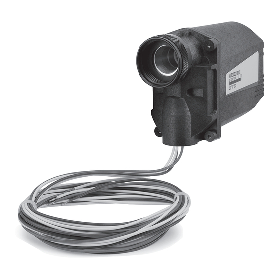
AUD300C1000
Advanced Ultraviolet
Flame Detector
User's Manual
Thank you for purchasing an Azbil
Corporation product.
This manual contains information for
ensuring the correct use of this product.
It also provides necessary information
for installation, maintenance, and
troubleshooting.
This manual should be read by those who
design and maintain equipment that uses
this product. Be sure to keep this manual
nearby for handy reference.
Advertisement
Table of Contents

Subscribe to Our Youtube Channel
Related Manuals for Azbil AUD300C1000 Series


Summary of Contents for Azbil AUD300C1000 Series
- Page 1 No. CP-SP-1141E AUD300C1000 Advanced Ultraviolet Flame Detector User’s Manual Thank you for purchasing an Azbil Corporation product. This manual contains information for ensuring the correct use of this product. It also provides necessary information for installation, maintenance, and troubleshooting. This manual should be read by those who design and maintain equipment that uses this product.
- Page 2 If you should find an error or omission, please contact the azbil Group. In no event is Azbil Corporation liable to anyone for any indirect, special or consequential damages as a result of using this product. © 2008–2016 Azbil Corporation All Rights Reserved.
- Page 3 Conventions Used in This Manual ■ The safety precautions explained in the following section aim to prevent injury to the operator and others, and to prevent property damage. WARNING Warnings are indicated when mishandling this product might result in death or serious injury. CAUTION Cautions are indicated when mishandling this product might result in minor injury to the user, or physical damage to the...
-
Page 4: Safety Precautions
Safety Precautions WARNING Use this device only in combination with Azbil Corporation’s burner controllers. Make sure that this device does not detect ultraviolet rays other than those of the burner flame. If it responds to other ultraviolet radiation, flame failure in the burner will not be detected. - Page 5 CAUTION This device is designed for both batch operation of the burner (at least one start and stop in a 24-hour period) and continuous operation (nonstop combustion for 24 h or longer). It must be used with a burner controller having a dynamic self-checking function. Installation, wiring, inspection, adjustment, etc., should be carried out by a trained and experienced technician with knowledge and technical skills related to combustion equipment and flame safeguard control devices.
-
Page 6: The Role Of This Manual
A total of 4 different manuals are available for the AUD300C1000, AUR300C. Read them as necessary for your spe- cific requirements. If a manual you require is not available, contact the azbil Group or its dealer. AUD300C1000 Advanced Ultraviolet Flame Detector Manual No.CP-SP-1141E... -
Page 7: Table Of Contents
Contents Conventions Used in This Manual Safety Precautions The Role of This Manual Chapter 1. OVERVIEW ■ ■ Overview ■ ■ Features ■ ■ Names of parts ■ ■ Model selection table Chapter 2. MOUNTING ■ ■ What to know before installation ■... - Page 8 Chapter 7. SPECIFICATIONS ■ ■ Specifications ■ ■ External dimensions Terms and Conditions...
-
Page 9: Chapter 1. Overview
Chapter 1. OVERVIEW ■ Overview The AUD300C1000 Advanced Ultraviolet Flame Detector (hereafter this/the de- vice) is designed to detect ultraviolet radiation from an oil or gas burner flame, for use with both batch and continuous operation burners. The AUD300C1000 is used in combination with a dedicated burner controller. - Page 10 Chapter 1. OVERVIEW ● Certification • UL: File No. MH27717 • CSA: Master Report LR 078402 • CE*: Gas Appliance Directive 0063BS1427 (with AUR450C_2_ _ _ _ _ and Q241A104) 0063CN6671 (with RX-R4_C_ _ _ _ _ ) RoHS Directive * CE marking appears to comply with RoHS ●...
-
Page 11: Chapter 2. Mounting
Chapter 2. MOUNTING WARNING Before mounting or removing, be sure to turn off the power to this device and all connected devices. Failure to do so may result in electric shock. If this device is installed near a source of ultraviolet rays other than the burner flame or in an atmosphere that interferes with UV rays, as described below, take sufficient countermeasures. -
Page 12: Methods Of Monitoring Burner Flame
Chapter 2. MOUNTING ■ Methods of monitoring burner flame ● Monitoring of the pilot flame only (continuous, intermittent pilots) The main burner must be reliably ignited even with the smallest pilot flame that this device can detect. For this reason, throttle the pilot manual fuel valve so that the main burner can be barely ignited. -
Page 13: Mounting Orientation
Chapter 2. MOUNTING Handling Precautions • If the above temperature range is not observed, a malfunction of the tube unit or shutter unit of this device, or unnecessary shutoff, may occur. • When this unit is not being used to detect a flame, do not allow the ambient temperature to exceed 100 °C. -
Page 14: Mounting Of The Monitoring Pipe
Chapter 2. MOUNTING The allowable range of the mounting posture is that the upper limit is 90° (conduit tube port becomes horizontal) and the lower limit is 45°. Upper limit 90° 90° Horizontal plane 45° Vertical plane Side Lower limit 45° Handling Precautions •... - Page 15 Chapter 2. MOUNTING ● Mounting space Leave a sufficient space for easy maintenance, inspection, and service work. Reducing socket AUD300C Monitoring pipe, 1" or more (Use 2" to 3" pipe.) Tees Furnace wall Tapered monitoring hole Connection nipple (1") Weld this part Burner Plate...
-
Page 16: Mounting Procedure
Chapter 2. MOUNTING ● Temporary welding for monitoring pipe positioning (1) Preparing a monitoring pipe and making the mounting hole Make the mounting hole at the selected location for the monitoring pipe. Cut threads on one end of the monitoring pipe and cut it to the desired length, making it as short as possible. -
Page 17: Chapter 3. Wiring
Chapter 3. WIRING WARNING Before doing any wiring work, be sure to disconnect the equipment power to prevent electrical shock. When measuring the voltage between terminal F and terminal G of this device in order to check the wiring, do not touch any part of the terminals. Doing so may result in an electric shock. CAUTION Installation, wiring, inspection, adjustment, etc., should be carried out by a trained and experienced technician with knowledge and technical skills related to combustion equipment... -
Page 18: Wiring Check
Chapter 3. WIRING ■ Wiring check Before applying voltage to this device, check that the wiring is correct. ● Steps (1) In the relay box, disconnect the blue and yellow wires that come from the AUD300C. (2) Turn on the power to the burner controller. (3) Measure the DC voltage between terminals F and G in the relay box using a circuit tester or a digital voltage meter. -
Page 19: Chapter 4. Adjustment
Chapter 4. ADJUSTMENT ■ Before measuring the flame voltage Before measuring the flame voltage, execute an operational check of this device using the flame voltage output terminals of the burner controller. Model No. Flame voltage output terminals AUR300C Terminal 9 (+) AUR350C Terminal10 (−) AUR450C... -
Page 20: Pilot Turndown Test
Chapter 4. ADJUSTMENT ■ Pilot turndown test This test is intended to check that any pilot flame detected by this device will reli- ably ignite the main burner, even if the gas pressure and air pressure have changed to their worst possible conditions. WARNING To prevent explosion, carry out the pilot turndown test carefully. -
Page 21: Ignition Spark Response Test
Chapter 4. ADJUSTMENT ■ Ignition spark response test WARNING Make sure that this device does not detect ultraviolet rays other than those of the burner flame. If it responds to other ultraviolet rays, flame failure in the burner will not be detected. As a result, fuel will continue to be discharged, causing a very serious explosion hazard. -
Page 22: Chapter 5. Troubleshooting
Chapter 5. TROUBLESHOOTING WARNING Before removing, mounting, or wiring this device, be sure to turn off the power to the device and all connected devices. Failure to do so may cause electric shock. Do not touch terminals F or G on this device or on the burner controller immediately after the power to the burner controller has been turned OFF. -
Page 23: Chapter 6. Maintenance And Inspection
Chapter 6. MAINTENANCE AND INSPECTION WARNING Before mounting, removing, or wiring this device, be sure to turn OFF the power to the module and any connected devices. Failure to do so may result in an electric shock. Do not touch terminals F or G on this device or on the burner controller immediately after the power to the burner controller has been turned OFF. -
Page 24: Replacement Of The Shutter Unit And Tube Unit Using The Aud Maintenance Kit (Aud60A1000)
If the burner manufacturer provides specific instructions for maintenance and inspection, be sure to observe them. • For inquiries about device failure, repair service, etc., contact the azbil Group. ■ Replacement of the shutter unit and tube unit using the AUD Maintenance Kit (AUD60A1000) - Page 25 Chapter 6. MAINTENANCE AND INSPECTION ● Mounting the shutter unit onto the flange unit (1) Fit the O-ring that is included in the AUD Maintenance Kit onto the flange unit. (2) Loosen the 2 screws holding the new (AUD Maintenance Kit) tube unit and remove the tube unit, holding it by the back of the unit.
- Page 26 Chapter 6. MAINTENANCE AND INSPECTION Handling Precautions • Terminals S1 and S2 do not have a specified polarity. When using a multime- ter, before measuring the shutter voltage check the polarity using a wide volt- age range so that the needle does not go off the scale on the minus side. >>...
- Page 27 Chapter 7. SPECIFICATIONS ■ Specifications Item Description Compatible flame* Flame from natural gas, propane gas, kerosene, heavy oil, coke oven gas, hydrogen, chlorine, ammonia, naphtha, ethylene, etc. Shutter voltage Approx. 24 Vdc (supplied from burner controller) Self-checking cycle Approx. 80 cycles/min Insulation resistance Between flange unit mounting conduit and F-terminal (or blue lead wire), between flange unit mounting conduit and G-terminal (or yellow lead wire),...
- Page 28 Chapter 7. SPECIFICATIONS ■ External dimensions Unit: mm 153.5 140.0 54.5 24.5 (104.6) Parallel pipethread 23.7 Conduit tube connection port 1/2-14NPSM...
- Page 29 Revision History (CP-SP-1141E) Printed Edn. Revised pages Description Apr. 2003 July 2004 Mass 450 g → 630 g Model No. changed AUD10C to AUD10C1000, AUD300C to Oct. 2006 AUD300C1000, AUD50A to AUD50A1000. List of model No. added. Cover 81446925-001 and Analog flame meter FSP136A100 added. ●...
- Page 30 1. Warranty period and warranty scope 1.1 Warranty period Azbil Corporation's products shall be warranted for one (1) year from the date of your purchase of the said products or the delivery of the said products to a place designated by you.
- Page 31 Azbil Corporation's products every 5 to 10 years unless otherwise specified in specifications or instruction manuals.
- Page 32 Specifications are subject to change without notice. (09) 1-12-2 Kawana, Fujisawa Kanagawa 251-8522 Japan URL: http://www.azbil.com 1st edition: Apr. 2003 12th edition: Nov. 2016 (F)
Need help?
Do you have a question about the AUD300C1000 Series and is the answer not in the manual?
Questions and answers