Rigol MSO2000A Series Quick Manual
Digital oscilloscope
Hide thumbs
Also See for MSO2000A Series:
- Programming manual (376 pages) ,
- User manual (335 pages) ,
- Quick manual (43 pages)
Table of Contents
Advertisement
RIGOL
Quick Guide
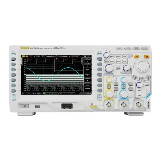
MSO2000A/DS2000A Series
Digital Oscilloscope
RIGOL(SUZHOU) TECHNOLOGIES INC.
May 2019
Distribution in the UK & Ireland
Lambda Photometrics Limited
Lambda House Batford Mill
Harpenden Herts AL5 5BZ
United Kingdom
E:
info@lambdaphoto.co.uk
W: www.lambdaphoto.co.uk
T:
+44 (0)1582 764334
F:
+44 (0)1582 712084
Advertisement
Table of Contents


Need help?
Do you have a question about the MSO2000A Series and is the answer not in the manual?
Questions and answers