Table of Contents
Advertisement
Quick Links
1P398933-1C (M15B230A)
Remote Control PC-Board Set
Safety Considerations
• Read these Safety Considerations carefully to ensure correct
installation.
• This manual classifies the precautions into WARNING and CAUTION.
Be sure to follow all the precautions below: they are all important for
ensuring safety.
WARNING : Failure to follow any of WARNING is likely to result
in such grave consequences as death or serious
injury.
CAUTION : Failure to follow any of CAUTION may in some
cases result in grave consequences.
• Installation shall be left to the authorized dealer or another
trained professional.
Improper installation may cause water leakage, electrical
shock, fire, or equipment damage.
• Be sure to use the supplied or exact specified installation parts.
Use of other parts may cause the unit to come to fall, water
leakage, electrical shock, fire or equipment damage.
• Be sure to switch off the unit before touching any electrical parts.
• Be sure to install a ground fault circuit interrupter / earth
leakage circuit breaker.
Failure to install a ground fault circuit interrupter / earth
leakage circuit breaker may result in electrical shock, fire or
personal injury.
• Do not install the air conditioner where gas leakage would
be exposed to open flames.
If the gas leaks and builds up around the unit, it may catch fire.
• Touch a nearby metal object (doorknob, aluminium sash,
etc.) to discharge static electricity from your body before
touching this set.
(Static electricity from your body can damage this set.)
• Lay the cable separately from other power cables.
(Poor wiring may cause external electrical noise.)
• After completing installation, test the unit to check for
installation errors. Give the user adequate instructions
concerning the use and cleaning of the unit according to the
Operation Manual.
Installation Position
Installation Manual
WARNING
CAUTION
Installation Procedure
Electrical
wiring box
Installation
position
of the set
Electrical
wiring box
<KRP067A41, KRP067A41E>
Outline / Features
This set is an interface that connects a central control device to a room
air conditioner and allows you to perform the following operations, or
monitoring, in combination with the central control device using
KRP413AB1S or KRP928BB2S (sold separately).
• Starting and stopping the air conditioner, and setting the mode and
temperature, through the central control device or the wired remote controller.
(64°F to 90°F (18°C to 32°C) in COOL operation, 57°F to 82°F (14°C to 28°C)
in HEAT operation, none in FAN operation)
• Monitoring the operating conditions, occurrence of errors, and contents of
errors of the air conditioner through the central control device or the wired
remote controller.
• Restricting the operation with a wireless remote controller found near the air
conditioner, such as starting and stopping operation, changing the mode, or
setting the temperature, through the use of the central control device, coin
timer, or card key.
• Zone control through the central control device.
• Restoring the operating conditions of the air conditioner to the previous
conditions at the time of power recovery in case of power outage.
This set does not support the following functions.
• Group control (i.e., the control of multiple indoor units through a single
remote controller)
• Monitoring of the following items: Indoor temperature and operating
conditions of thermo, compressor, indoor fan, electric heater, and humidifier
• Control of the following items: Forced thermo OFF, filter sign display and
reset, airflow direction, airflow rate setting, and air-conditioner charge
management
• Energy-saving command, low-noise command, and demand command
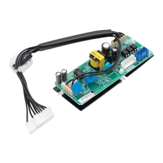
This set includes the following components. Please confirm them.
Component
Main
component
Wiring Outline
This set
To central control
device
Option:
S21
KRP413AB1S
KRP928BB2S
PCB of indoor unit
Components
Quantity
Component
Installation
1
Manual
Inside the indoor unit
S602
S601
S403
Note:
Wires indicated by
thick lines
are not included
with the set.
Quantity
1
Advertisement
Table of Contents

Related Manuals for Daikin KRP067A41


Summary of Contents for Daikin KRP067A41
- Page 1 1P398933-1C (M15B230A) Remote Control PC-Board Set <KRP067A41, KRP067A41E> Installation Manual Safety Considerations Outline / Features • Read these Safety Considerations carefully to ensure correct This set is an interface that connects a central control device to a room installation. air conditioner and allows you to perform the following operations, or monitoring, in combination with the central control device using •...
- Page 2 Removal and Installation of Front Panel Opening Service Lid of Indoor Unit • Removal method The service lid is of removable type. 1) Place your fingers in the indentations on the main unit • Opening method (one each on the left and right sides), and open the panel until it stops.
- Page 3 Removal of Electrical Wiring Box Cover 1. Remove the front panel and the front grille and service lid of indoor unit. WARNING (Refer to the front page for the removal of each part in detail.) • Be sure to turn OFF the power at the time of 2.
- Page 4 Connecting HA PCB 1. Install the HA PCB (this set). (See Fig. 1) 1) Install the HA PCB (this set) to the electrical wiring box. 2) Insert the connector of the HA PCB (this set) to the connector (S403) on the electrical wiring box. 2.
Need help?
Do you have a question about the KRP067A41 and is the answer not in the manual?
Questions and answers